Yes, another CB360 Project - BRGT

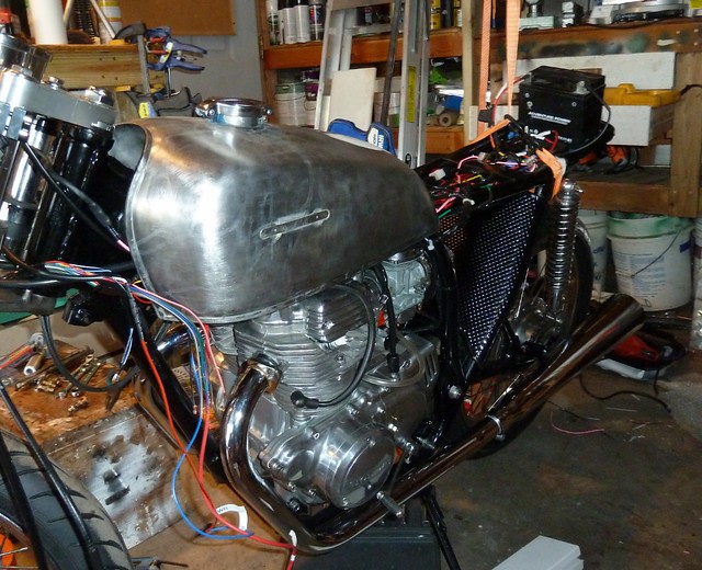
Wiring coming off the stator is simple if you feed it to the unit. TIE YELLOW and WHITE together. I take the stator out and do it right at the windings but outside is fine.

PINK is COMMON for both windings. YELLOW and PINK will SEE Positive and negative AC voltage. Those go to the pins marked AC on the unit, doesn't matter which.

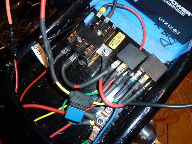
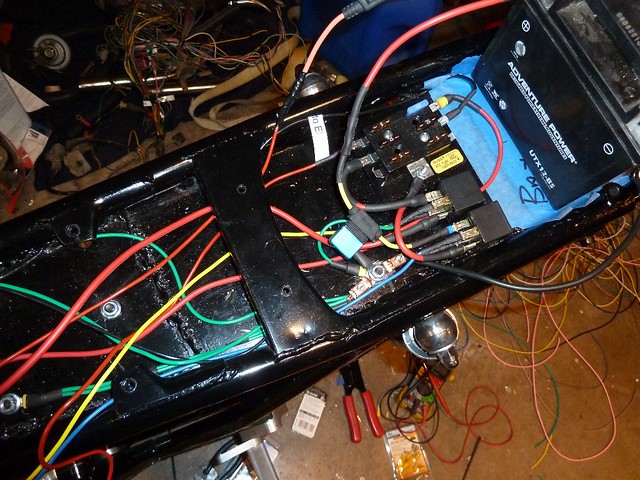
A red wire should go from the + terminal on the unit to the POS on the battery. Or a fuse then the battery. The unit itself needs to be grounded to the frame. Either by attaching it to a good ground point or wiring one in like I suggested into the GREEN on the harness.

Make sure you do very good job attaching the terminals. These guys will vibrate enough to shake them loose if you don't, I know I have had it happen. I ended up soldering the wires right the the terminals.

Shoot me a another email or PM if you need too. Wiring is a second language for me.
 
Sonreir, 3DogNate and Frogman - Thanks guys for confirming the wire positions. Once I get this mounted and Viet's EI setup, I believe the rest of the wiring should go smoothly. :D
 
mattfeet said:
From the resting position of the brake pedal, how far down is max travel? Im worried about hitting my exhaust hard if I lock up the rear.

Matt - My brake pedal travel is 3/4 - 1". Especially after I installed new shoes. But that is with the wheel static, no forward motion. I'm sure it will require a little more when the bike is moving and things heat up. As to exhaust - I'm waiting to purchase my exhaust setup. I may find that I'll need to adjust my rearsets accordingly. You've got your exhaust to work with, and since I don't, I'm not able to offer much advice for you.

mattfeet said:
Also, I CANNOT get that rear pin through the brake actuating arm. It's nearly impossible without dropping the swingarm.
I'm not sure exactly what trouble you're having, but I do know that I had to really finagle with the rear swingarm to get things to come together. But, I'm sure you can make it happen. You might have to loosen things up, and move things around, and make your connections and then put things back together again.

A photo would help tremendously. If you can photograph your issue perhaps people can give you better advice. Don't get frustrated! ;)
 
Well, I did get frustrated, but I finally got it. Ill be posting a ton of pics up tomorrow. :) Thanks for the help, Wango.

-Matt
 
Re: Yes, another CB360 Project - Electronic Ignition

Well, slowing getting things wired up. I have Viet's EI module mounted, and enough things wired up to give it a static test. I swiped the battery off my scooter and tested it out. If a picture is worth a thousand words a video must be worth 10,000. I posted my testing on youtube below.

As power is hooked up to the unit, both led's light up. As the magnet in the outer magnet plate moves over the sensor, the corresponding LED gets brighter, letting you know when power would be sent to the plug.

With the module mounted "upside down", the "right" LED lights up when LF hits the mark, and the "left" LED lights up when the F hits the mark. Hopefully I don't have these reversed. Perhaps Viet can speak to this.

One other thing I'm not sure of is the black/white wires coming off the coils. The EI doesn't use the condensor, so its' been removed. The original coil is connected, but I'm not sure what to do with the black/white wire. Not sure if those need to be grounded or just ignored. Again, another question for Viet.

Hope this encourages others to consider this option. Probably in a week or so I'll fire her up.

http://www.youtube.com/watch?v=l_6_LRzv5n0
 
Wangofree said:
One other thing I'm not sure of is the black/white wires coming off the coils. The EI doesn't use the condensor, so its' been removed. The original coil is connected, but I'm not sure what to do with the black/white wire. Not sure if those need to be grounded or just ignored. Again, another question for Viet.
Dear Mike,
The stock coils after removed the condenser will have 2 wires out on each coil. It is Honda standard that yellow or green/ blue will be connected to signal wire from EI. The black is go to +12v on the ignition switch. It means stock coils always got connected to positive 12v when you turn the switch on. This is a weakness on Honda as if you leave the bike with the switch us on, it heat up the coil and in almost cases, run off the battery whilst in worst case, kill the coil.
Hope to see the engine running soon.
Many thank
Viet
 
So Viet, if I understand you correctly, the EI will light up as I have it installed, but the coil will only work properly if I have the black/white wires running to the +12v ignition? That's an easy fix. Thanks.

Mike
 
nice vid! I take it that the pickups are individually adjustable? so you can get em both on the money.
 
The sensors are solidly attached to the sensor plate. I'm sure it's just a matter of me getting the LF adjusted correctly and the F will follow. Thanks Trek.
 
That is lookin nice.
I am using this relay to feed power to my coils directly from battery w minimum connections. Cleaner, happier power. the relays coil is wired through the kill sw and key.
I like it cause it has a permanently wired base. also you can get replacement relays at any auto store and they just plug right in. for like $5 bucks. This is the only one Ive gotten and its going on its 3rd season now. pretty reliable so far.

http://www.amazon.com/gp/product/B00009WC2Q/ref=oh_details_o03_s00_i00?ie=UTF8&psc=1
 
Still wiring the bike. Not sure how I'm going to get it all under the seat. Does anyone have a wiring diagram?


Seriously, bike is 88% wired. I have good solid blue spark on both sides. Viet's electronic ignition is only a couple of days away from getting a trial. I hope to fire up and post video late Friday or Saturday. ;D

Opted for MAC 2 into 2 pipes. I found that I had to ditch the Honda exhaust pipe rings. Is that normal, or do I need longer mounting bolts? I'm cool without them. Just curious.

 
Wangofree said:
I found that I had to ditch the Honda exhaust pipe rings. Is that normal, or do I need longer mounting bolts? I'm cool without them. Just curious.

My Jardine exhaust should have came with different collars and rings as a kit(but it was over 10 years old, and parts were lost).

I was able to use CB350F collars, which are deeper than the cb360's.

It was necessary because the mounting flange on the Jardine exhast is only about an 1/8" tall.

Factory exhaust has much more on the flange, like 3/4", thus using a shallower collar.

So you may be able to use the factory rings if the collars are the right size.

. . . and because the 350 four is a four cylinder, I have two cylinder's worth of collars left over.
 
That's cool, from that angle that fender insert looks like carbon fiber.

Rings? Collars? No use the ones that come with the kit if they hold you are good to go. Make sure to replace the copper gaskets though. Don't do like the PO did on my 450 and stack multiple sets. :eek: ;D
 
Wangofree said:
Still wiring the bike. Not sure how I'm going to get it all under the seat. Does anyone have a wiring diagram?

Is that supposed to be funny? Dude... Don't make the wires any longer than they need to be. Spaghetti wiring is no good for trouble shooting later... The best stock wiring diagram I found for my 74, that matched the colors on my hand controls was:
http://www.oregonmotorcycleparts.com/Diagrams/CB-CL360.jpg

Aside from that... I'm still waiting for it to get fired up... I too have an Ei kit from Viet on the way. :)
 
3DogNate said:
Is that supposed to be funny? Dude...

Nate - It's a joke. I just stacked unused wires on bike for grins. The only thing left to wire up are turn signals and the headlight.

I will try to kick some life into this baby late tomorrow, or Sat afternoon. I'll PM you when the video is posted.

Thanks guys for input on exhaust rings.

Mike
 
Back
Top Bottom