
We noticed you are blocking ads. DO THE TON only works with community supporters. Most are active members of the site with small businesses. Please consider disabling your ad blocking tool and checking out the businesses that help keep our site up and free.
You are using an out of date browser. It may not display this or other websites correctly.
You should upgrade or use an alternative browser.
You should upgrade or use an alternative browser.
Simplified Wiring Digrams
- Thread starter Sonreir
- Start date
namelesspenguin
New Member
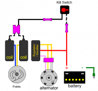
hey guys, I drew up this basic wiring diagram for my project. before I actually get started on it, wanted you guys to look it over and see if its all good. let me know if ive missed someing or something isn't wired right. thanks guys.


SONICJK
Reminds me of...me No, I'm sure of it. I hate him
namelesspenguin said:hey guys, I drew up this basic wiring diagram for my project. before I actually get started on it, wanted you guys to look it over and see if its all good. let me know if ive missed someing or something isn't wired right. thanks guys.
I fixed a couple of things in your other post.
timberwolffxdl
Been Around the Block
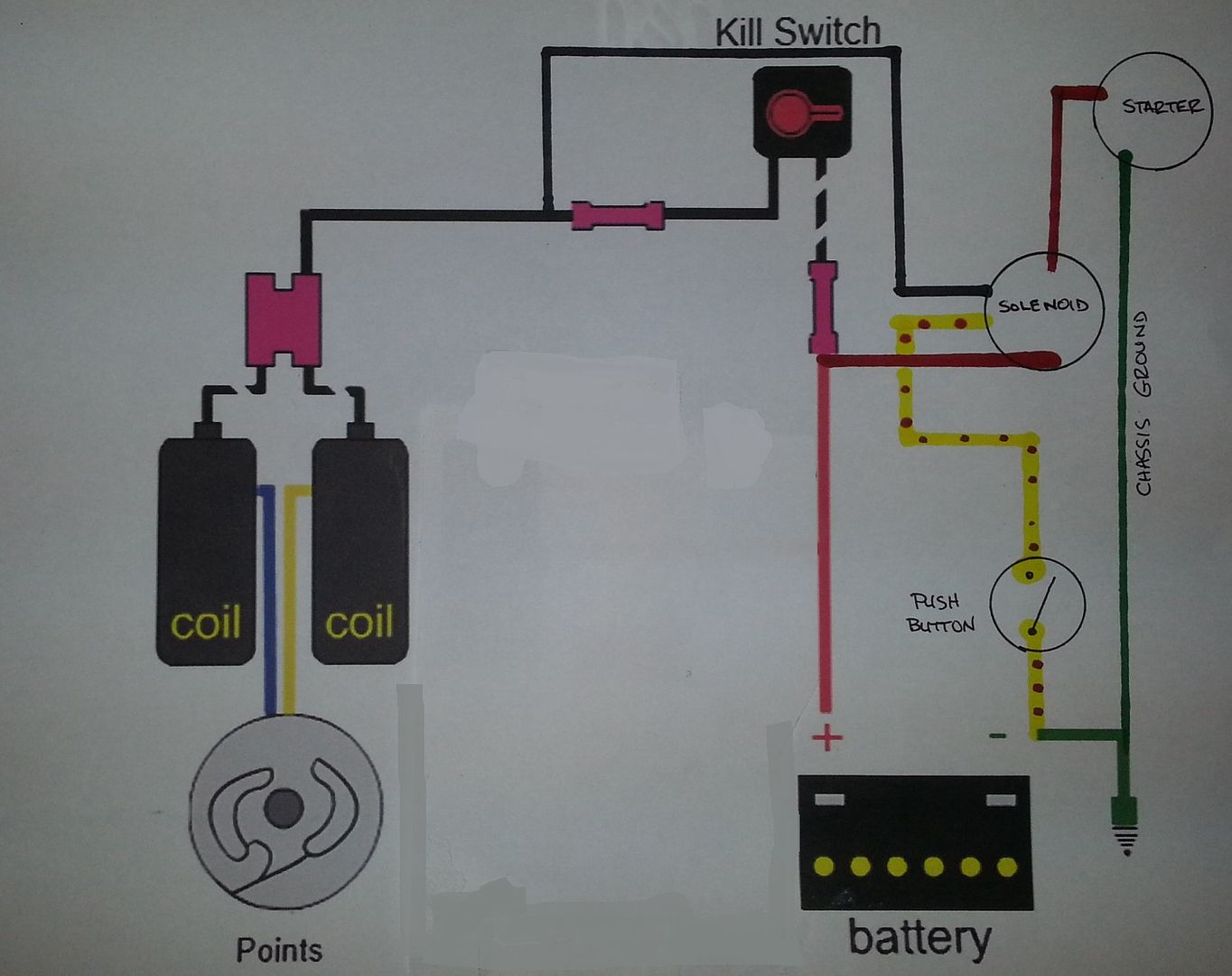
I PM'd you, but I think this will give me what I need. Just wanted to double check though... chassis ground to the body of the coil mount is really the only thing not shown, correct? And I can just leave the entire R/R section out for a total loss circuit, correct? The electric start wiring is easy enough.Sonreir said:Barebones diagram for the Honda twins and singles. Only enough to get the bike running and keep it that way. No lights, signals, or gauges included. Though not pictured, I recommend a 5A fuse on the black wire leading to the coils.
Attachments
timberwolffxdl said:I PM'd you, but I think this will give me what I need. Just wanted to double check though... chassis ground to the body of the coil mount is really the only thing not shown, correct? And I can just leave the entire R/R section out for a total loss circuit, correct? The electric start wiring is easy enough.
Correct on most counts. The coils don't (strictly) need to be grounded though.
timberwolffxdl
Been Around the Block
ok, one other question... I don't think the 360 are waste spark, so it should matter which cylinder the plug wires go to from the coil. Probably a dumb question, but is it blue/left, yellow/right (as seated on the bike) or vice versa?
timberwolffxdl
Been Around the Block
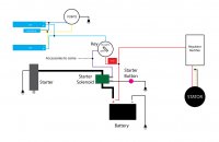
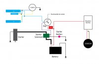
sounds good. So does this seem reasonable for a total loss system that includes a starter (this will be on my starting stand).
bananas
Been Around the Block
I've been attempting to draw a wiring diagram for my DOHC CB750 and I haven't yet seen another DOHC diagram on here so I figured I'd ask. Electrical things are a black art to me but I'd love to get a basic understanding of whats going on.
Just to add, I plan to use a motogadget m-unit control system.
I found this on another forum (through googling). So my question is, if I combine the two diagrams, will this work? Iirc the M-unit removes the need for fusebox?


Thanks!!!
Just to add, I plan to use a motogadget m-unit control system.
I found this on another forum (through googling). So my question is, if I combine the two diagrams, will this work? Iirc the M-unit removes the need for fusebox?
Thanks!!!
Sonreir said:If you're running without a kill switch, power going to the coils and power going to the solenoid should come from the same source.
Updated, I hope this is what you meant. Thanks for the help!
Attachments
bananas
Been Around the Block
Hey Sonrier,
I've made a first attempt based on a combination of the two wiring diagrams. I hope this makes sense. Left out the obvious ones.

Features:
-Headlight always on (no switch)
-Kill button is [START]x2, No kill/Run switch
-No kickstand/ clutch safety switches
I've made a first attempt based on a combination of the two wiring diagrams. I hope this makes sense. Left out the obvious ones.
Features:
-Headlight always on (no switch)
-Kill button is [START]x2, No kill/Run switch
-No kickstand/ clutch safety switches
Red/white coming off of the ignition switch is only for the solenoid. All other power sources should be fed from Acc or Ign poles. Acc is the first and second "clicks" on the ignition and the Ign is the second click only. So Acc would be stuff like parking lights and Ign would be for ignition coils, head light, etc.
Thanks for the help Sonreir.
Two questions if you could help me out.
On the ignition switch(Standard Square plug) there are 4 wires, Red, Black, Brown and Brown/White. I'm know red is power and I'm assuming black is ground, what I'm not sure is which colour after that corresponds to Ignition and Accessories.
Second question, on the solenoid (New ebay one), theres two screw posts and then two wires that come out, Red/Yellow and Green/Red. Again I'm assuming that one of the screw posts connects to the battery and the other to the starter. Then the Red/Yellow connects to the starter button and the Green/Red connects to the ignition switch (Which ever colour corresponds to ignition on the ignition switch) Does this sound right?
Thanks again!
bydgoszcz said:Thanks for the help Sonreir.
Two questions if you could help me out.
On the ignition switch(Standard Square plug) there are 4 wires, Red, Black, Brown and Brown/White. I'm know red is power and I'm assuming black is ground, what I'm not sure is which colour after that corresponds to Ignition and Accessories.
Second question, on the solenoid (New ebay one), theres two screw posts and then two wires that come out, Red/Yellow and Green/Red. Again I'm assuming that one of the screw posts connects to the battery and the other to the starter. Then the Red/Yellow connects to the starter button and the Green/Red connects to the ignition switch (Which ever colour corresponds to ignition on the ignition switch) Does this sound right?
Thanks again!
Sort of.
Red from ignition switch to battery +, black from ignition switch is your power. This goes to the green/red wire on your solenoid as well as off to the ignition coils, lights, etc. Yellow/red on the solenoid goes to your starter button and then button then completes the circuit to ground.
Brown and brown/white not needed unless you want parking lights.
Sonreir said:Sort of.
Red from ignition switch to battery +, black from ignition switch is your power. This goes to the green/red wire on your solenoid as well as off to the ignition coils, lights, etc. Yellow/red on the solenoid goes to your starter button and then button then completes the circuit to ground.
Brown and brown/white not needed unless you want parking lights.
You sir are a genius. Honestly I should have just read your other posts about wiring in the first place, found lots more answers in your Wire Color post. Thanks for the guidance!


