
We noticed you are blocking ads. DO THE TON only works with community supporters. Most are active members of the site with small businesses. Please consider disabling your ad blocking tool and checking out the businesses that help keep our site up and free.
You are using an out of date browser. It may not display this or other websites correctly.
You should upgrade or use an alternative browser.
You should upgrade or use an alternative browser.
Hi From Australia CB350
- Thread starter ducatiboy
- Start date
YEEEESSSSSSSSSS!!!!!!!!! ")
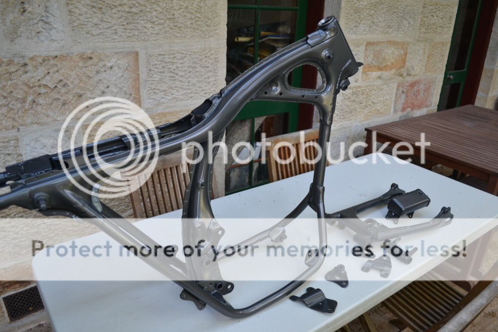
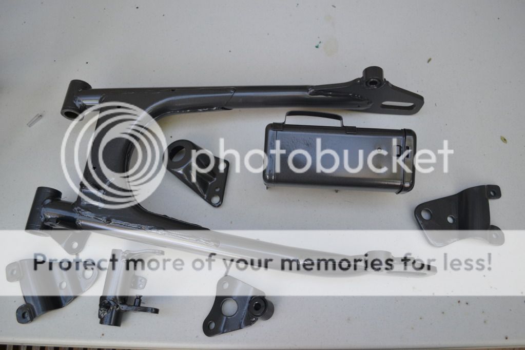
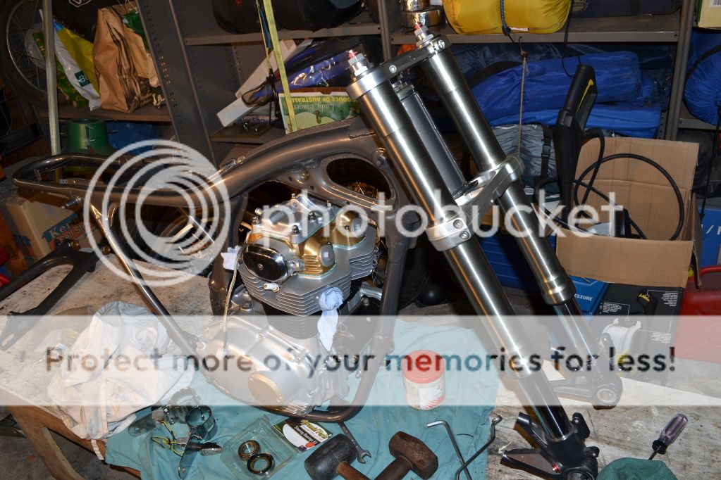
Got my frame and swing arm and various brackets back from painting. Sand blasted, prepped, and sprayed in two pack enamel, metallic grey with a satin finish in the manner of modern ducati frames. And it only took him 2 months (he's a VERY busy man... : but we won't go there). Looks fantastic!!
So looks like I'll be having a busy weekend in the garage. Engine in frame, back end on, front end on, make a wiring loom, locate electrical bits and pieces and we're just about done... Now have to decide on a colour for the tank and seat unit.

Got my frame and swing arm and various brackets back from painting. Sand blasted, prepped, and sprayed in two pack enamel, metallic grey with a satin finish in the manner of modern ducati frames. And it only took him 2 months (he's a VERY busy man... :
but we won't go there). Looks fantastic!!So looks like I'll be having a busy weekend in the garage. Engine in frame, back end on, front end on, make a wiring loom, locate electrical bits and pieces and we're just about done... Now have to decide on a colour for the tank and seat unit.
deepwaterimports
Over 1,000 Posts
looking wicked its like a gunmetal i dig it heaps getting close mate
axeugene27
Over 1,000 Posts
can't wait to see it come together again.
freedomgli
Been Around the Block
Nice project, man! Keep up the good work!
I'm also trying to understand my geometry and how it is changing as I swap forks, triple clamps, etc. In the Honda manual I'm not sure what to make of their specification for "Trail length." Is it ground trail? Or real trail? I assume it's ground trail. I've been using both Tony Foale's Steering Geometry Calculator and RB Racing's Advanced Trail Calculator and I'm not able to back track Honda's trail length calculations using either tool. I understand the CB350 fork offset is 60 mm (2.36 in) but in order to achieve a ground trail of 85 mm (3.35 in) with a 90/90-18 tire and 27° rake then the fork offset must be 64.8 mm (2.55 in). I don't have the parts and a caliper sitting in front of me so I can't verify the measurements myself!ducatiboy said:I then worked out the trail to be 173mm and it was at this stage that I decided I needed to maybe re-check my measurements because even the 848 triple clamp offset of 36 mm vs CB350 offset of 60mm would not account for 173 mm of trail! So my measurements are screwed and I'll need to do it all again.
Thanks for the comments gents
I've been piecing things back together over the last couple of days, photos to follow.
For a novice like me, working out the geometry hurts my head and everything somehow gets tangled up in my brain. When I measured my geometry I simply used a tape measure and a laser pointer, drew a triangle and worked out angles using Pythagoras Theorum. The important thing is to make sure you measure with the suspension at full extension but with tyres just touching the ground as having the weight of the bike compressing the springs alters rake, trail and ride height. I have not used a trail calculator before and might have to look at one of the ones you mentioned to see if it helps.
I've been piecing things back together over the last couple of days, photos to follow.
I'm also trying to understand my geometry and how it is changing as I swap forks, triple clamps, etc. In the Honda manual I'm not sure what to make of their specification for "Trail length." Is it ground trail? Or real trail? I assume it's ground trail. I've been using both Tony Foale's Steering Geometry Calculator and RB Racing's Advanced Trail Calculator and I'm not able to back track Honda's trail length calculations using either tool. I understand the CB350 fork offset is 60 mm (2.36 in) but in order to achieve a ground trail of 85 mm (3.35 in) with a 90/90-18 tire and 27° rake then the fork offset must be 64.8 mm (2.55 in). I don't have the parts and a caliper sitting in front of me so I can't verify the measurements myself!
For a novice like me, working out the geometry hurts my head and everything somehow gets tangled up in my brain. When I measured my geometry I simply used a tape measure and a laser pointer, drew a triangle and worked out angles using Pythagoras Theorum. The important thing is to make sure you measure with the suspension at full extension but with tyres just touching the ground as having the weight of the bike compressing the springs alters rake, trail and ride height. I have not used a trail calculator before and might have to look at one of the ones you mentioned to see if it helps.
ducatiboy said:For a novice like me, working out the geometry hurts my head and everything somehow gets tangled up in my brain.
Mate - don't overthink it. The new forks you have are pretty close to what was there originally as far as length, rake / trail, etc. If you were raking the front end and adding 6" over forks then you might be concerned, but what you have there will only be an improvement on the clapped-out 40 year old suspension you had prior to the swap.
And what are you going to do if you calculate you need another 8mm of trail anyway??
Carry on - it's looking pretty damn good
I take your point Hillsy about over thinking things. But I do like to learn about these things as much as I can and to understand what happens when changing various parameters.
After making so many changes to the hardware that influences geometry, the only way for me to know if I am "pretty close" to original geometry is to measure where I'm at. There are plenty of adjustments available to alter geometry if required, not the least of which is what length rear shocks I need to get. The original ones I have at the moment are the original sealed, non-rebuildable units which are now 42 years old and don't really seem to have any damping properties at all!! If I'm going to buy new shocks, the geometry of the bike as it currently sits will determine what length I need to get.
Anyway, the geometry is an issue for another day. No work today meant today was a day spent in the garage with the music up loud and the phone switched off. And this evening is the time for a massive update as progress on a monumental scale base been made.
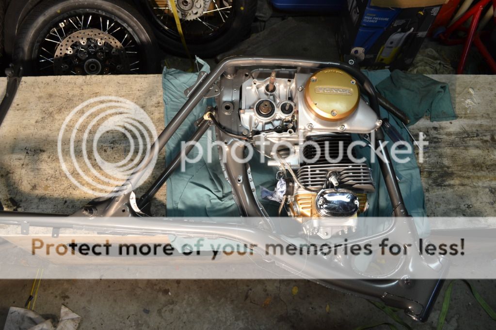
First off, got the engine in the frame. A little hint for anybody trying to do this without scratching the freshly painted frame or cases. It is a job that is one million percent easier with the starter motor and exhaust studs removed and the engine lying on it's side. Then just lower the frame on top, slight rotation, slide your engine bolts in and your done.
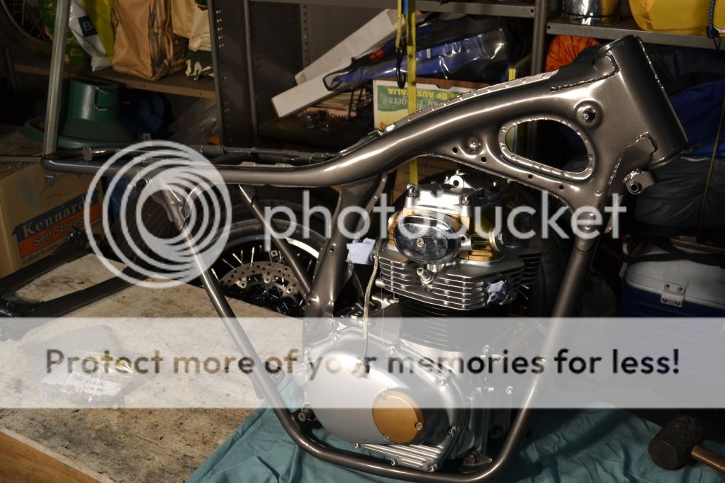
Front end on next. Plenty of grease on the new tapered roller bearings and torqued to spec
Next job was the swing arm. But first I had to install the new brass swing arm bushes. Put the new bushes in the freezer next to the frozen peas to shrink them (the bushes, not the peas)

While the new bushes are freezing, knock the old ones out
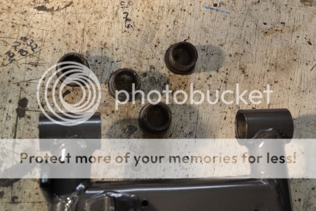
If you're a clumsy git, you will damage the interior of the swing arm when knocking the old bushes out

This will make pressing the new ones in very difficult, so sand down the damage
Knock the new (and now frozen) bushes in nice and easy. Take them out of the freezer one at a time and knock them in otherwise the last couple will have warmed up too much to easily go in. Voila!

Swingarm on next, don't forget the dust covers, grease nipples and LOTS of grease. Crank it up tight (How tight? FT!)
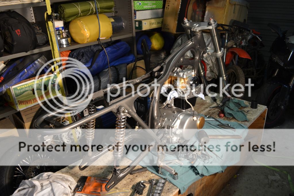
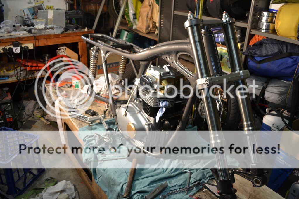
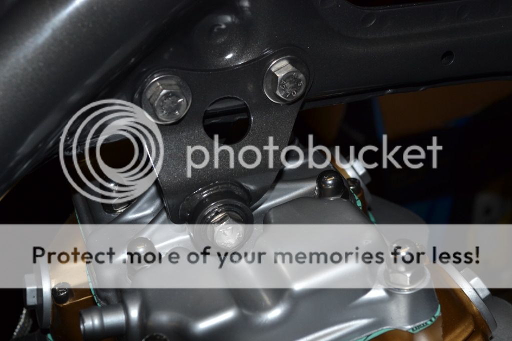
Top engine bracket and lovely new stainless bolts
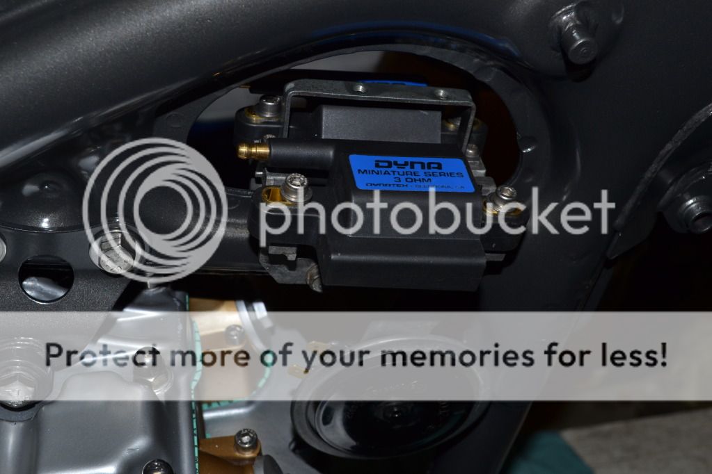
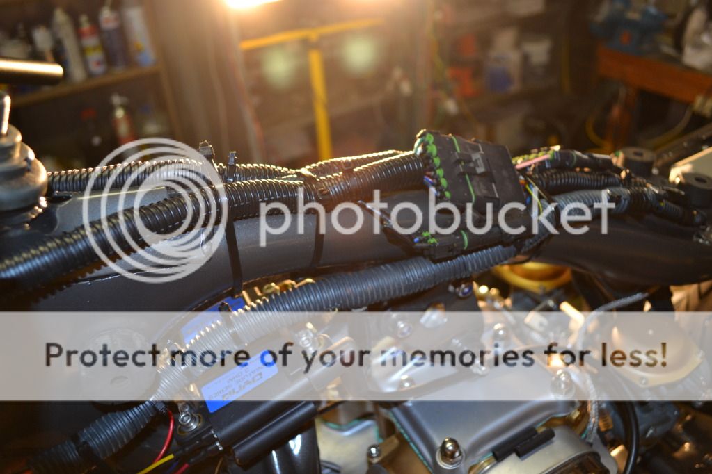
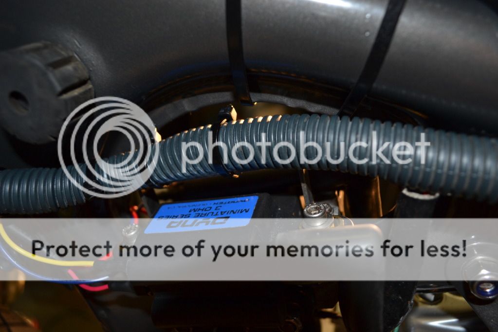
New Dyna coils and horn
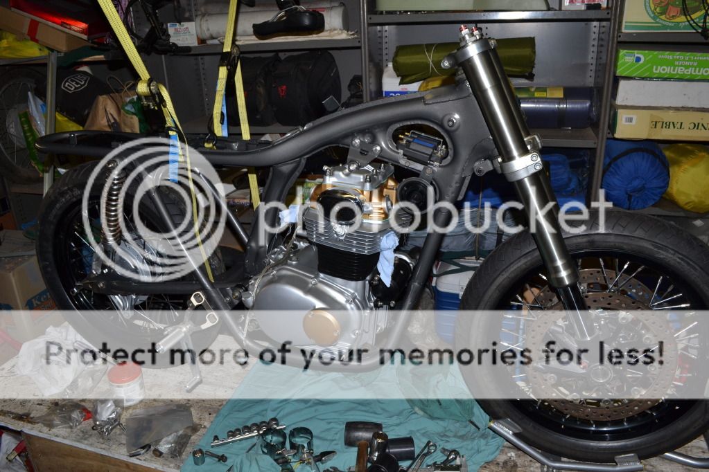
Loaded Gun foot pegs and wheels on
After making so many changes to the hardware that influences geometry, the only way for me to know if I am "pretty close" to original geometry is to measure where I'm at. There are plenty of adjustments available to alter geometry if required, not the least of which is what length rear shocks I need to get. The original ones I have at the moment are the original sealed, non-rebuildable units which are now 42 years old and don't really seem to have any damping properties at all!! If I'm going to buy new shocks, the geometry of the bike as it currently sits will determine what length I need to get.
Anyway, the geometry is an issue for another day. No work today meant today was a day spent in the garage with the music up loud and the phone switched off. And this evening is the time for a massive update as progress on a monumental scale base been made.
First off, got the engine in the frame. A little hint for anybody trying to do this without scratching the freshly painted frame or cases. It is a job that is one million percent easier with the starter motor and exhaust studs removed and the engine lying on it's side. Then just lower the frame on top, slight rotation, slide your engine bolts in and your done.
Front end on next. Plenty of grease on the new tapered roller bearings and torqued to spec
Next job was the swing arm. But first I had to install the new brass swing arm bushes. Put the new bushes in the freezer next to the frozen peas to shrink them (the bushes, not the peas)
While the new bushes are freezing, knock the old ones out
If you're a clumsy git, you will damage the interior of the swing arm when knocking the old bushes out
This will make pressing the new ones in very difficult, so sand down the damage
Knock the new (and now frozen) bushes in nice and easy. Take them out of the freezer one at a time and knock them in otherwise the last couple will have warmed up too much to easily go in. Voila!
Swingarm on next, don't forget the dust covers, grease nipples and LOTS of grease. Crank it up tight (How tight? FT!)
Top engine bracket and lovely new stainless bolts
New Dyna coils and horn
Loaded Gun foot pegs and wheels on
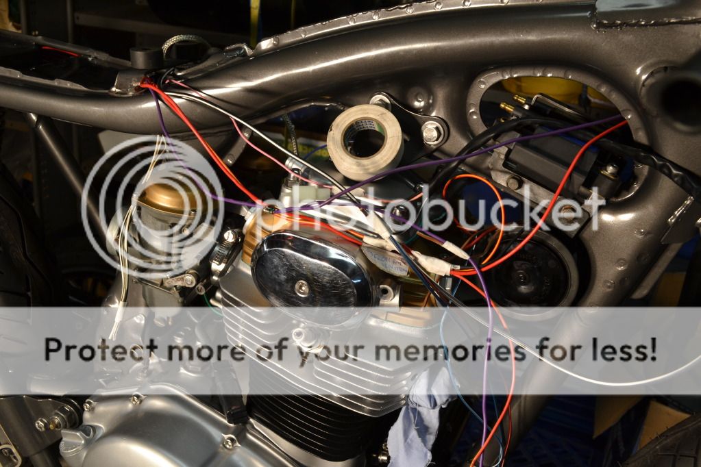
With the basic nuts and bolts back in position, it's now time to move on to the electrical bits and pieces
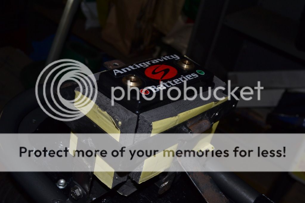
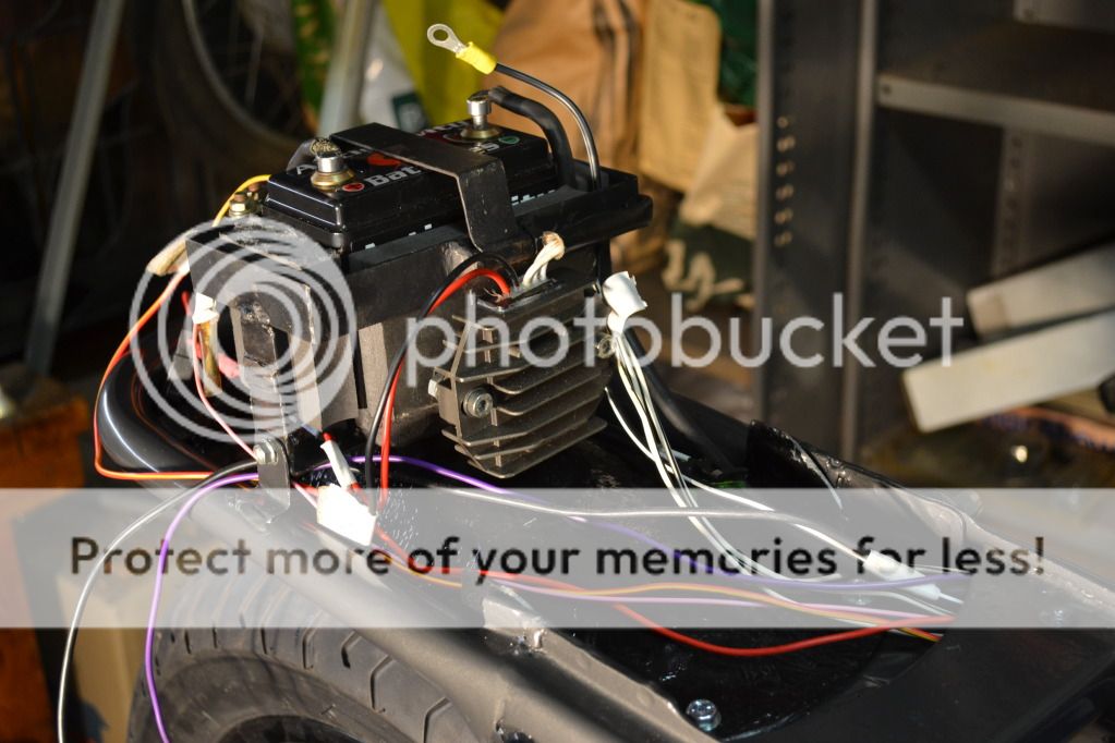
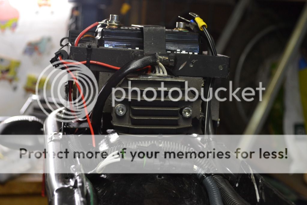
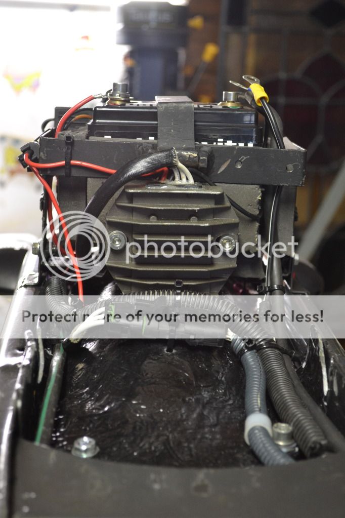
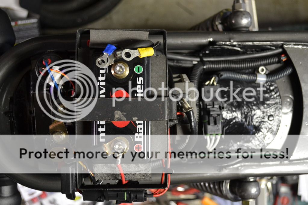
AntiGravity Battery under the seat hump. I'll be tearing the yellow paper off the sticky side of the foam padding
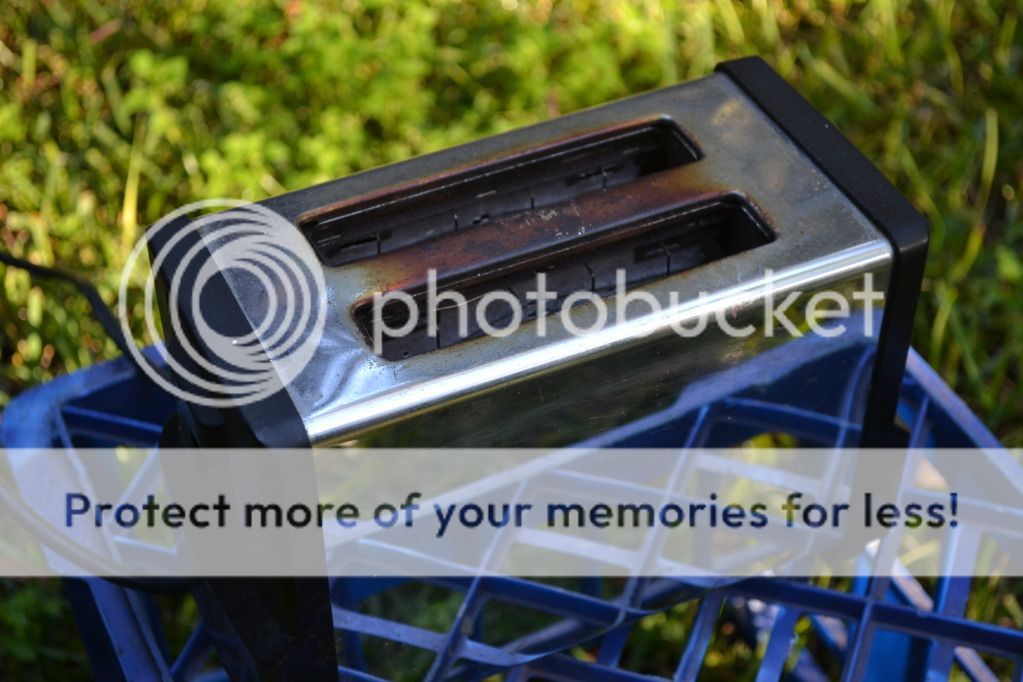
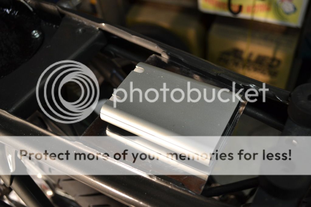
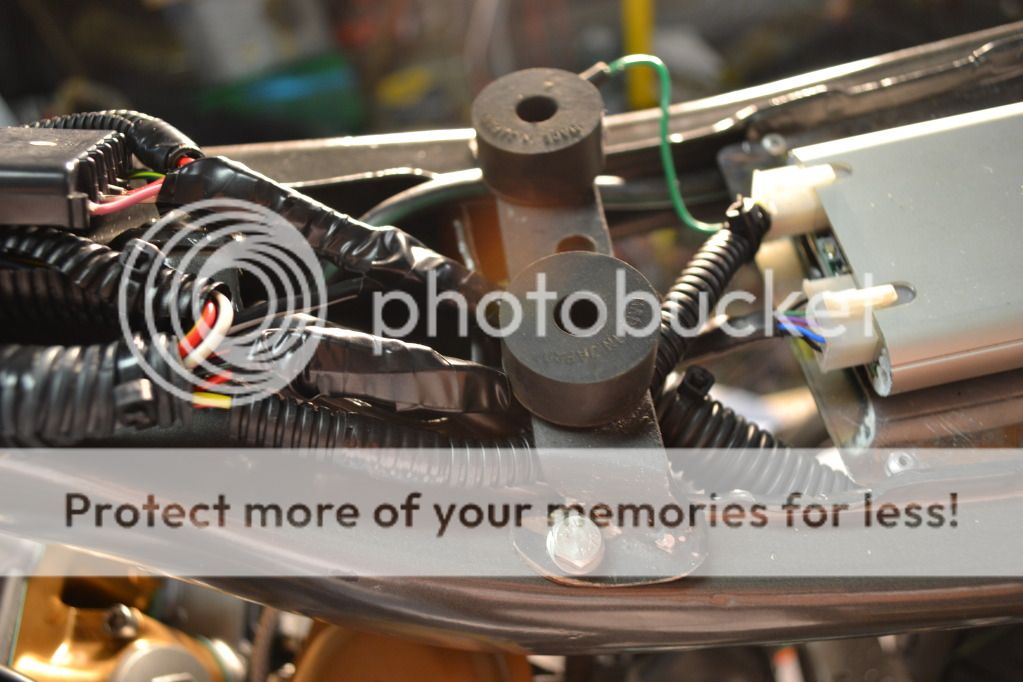
In trying to workout where to mount the electronic ignition control unit, I realised that I don't have a flat section big enough to mount it to. When I cut the flat seat pan out to allow more rear wheel travel, it inadvertently removed the only flat section to mount it. So I had to work out where I could put it. Below the tank and above the carburettors there is a big open space where I decided it could easily go. Not having any sheet metal, I racked my brains and searched the garage and found this old toaster that would perfectly do the job
Cut the side off
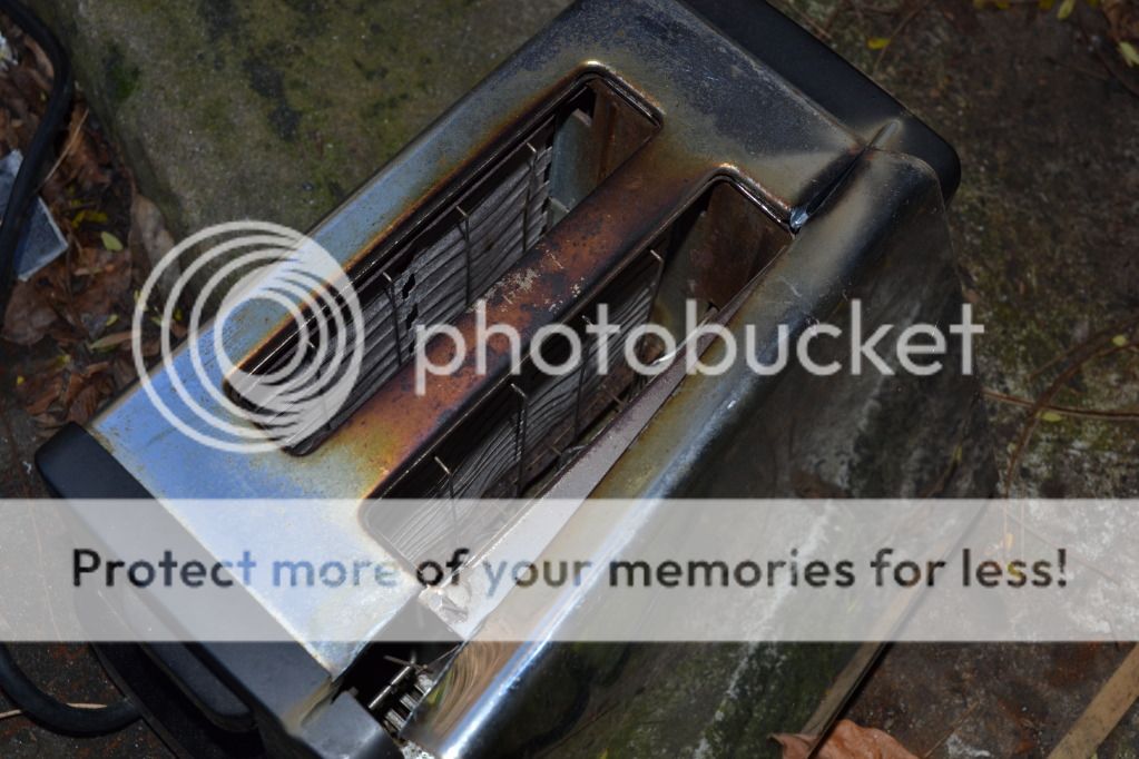
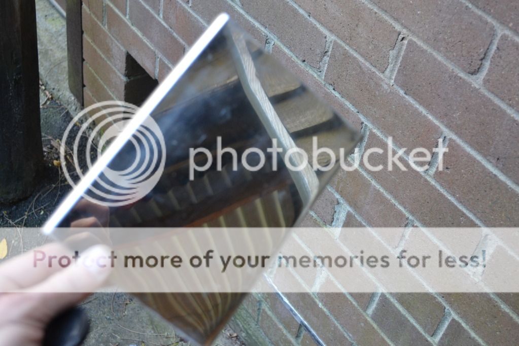
And cut to shape

Drill some holes

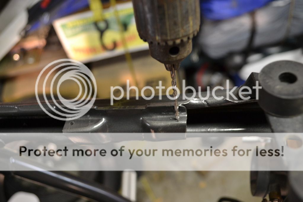
Voila!! Magnifico!!
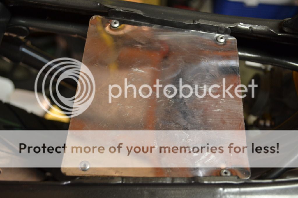
All to mount this thing
And then….onto the wiring loom. Starting from scratch. Who would've ever thought that wiring a 40 year old motorcycle from scratch could provide such unbridled joy?
So that's where I'm at. More wiring tomorrow and with any luck I'll get it finished (the wiring that is)
AntiGravity Battery under the seat hump. I'll be tearing the yellow paper off the sticky side of the foam padding
In trying to workout where to mount the electronic ignition control unit, I realised that I don't have a flat section big enough to mount it to. When I cut the flat seat pan out to allow more rear wheel travel, it inadvertently removed the only flat section to mount it. So I had to work out where I could put it. Below the tank and above the carburettors there is a big open space where I decided it could easily go. Not having any sheet metal, I racked my brains and searched the garage and found this old toaster that would perfectly do the job
Cut the side off
And cut to shape
Drill some holes
Voila!! Magnifico!!
All to mount this thing
And then….onto the wiring loom. Starting from scratch. Who would've ever thought that wiring a 40 year old motorcycle from scratch could provide such unbridled joy?
So that's where I'm at. More wiring tomorrow and with any luck I'll get it finished (the wiring that is)
deepwaterimports
Over 1,000 Posts
nice one, updates are great she will look sooooo good
If someone says to you that you can rewire a 40 year old motorcycle in half a day, my advice would be to tell them to fuck off and take their head out of their arse. I've spent about 30 hours on making a wiring loom and it's STILL NOT DONE!! Maybe it's just me… I never really understood electrons. They're too small. And too negative. I like to stay positive and not surround myself with such negativity. Maybe that's why it's taken me so long. :
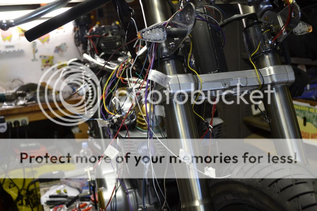
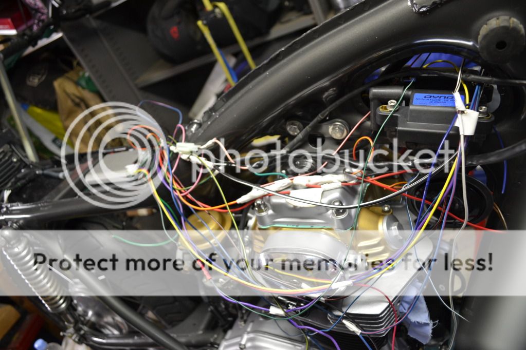
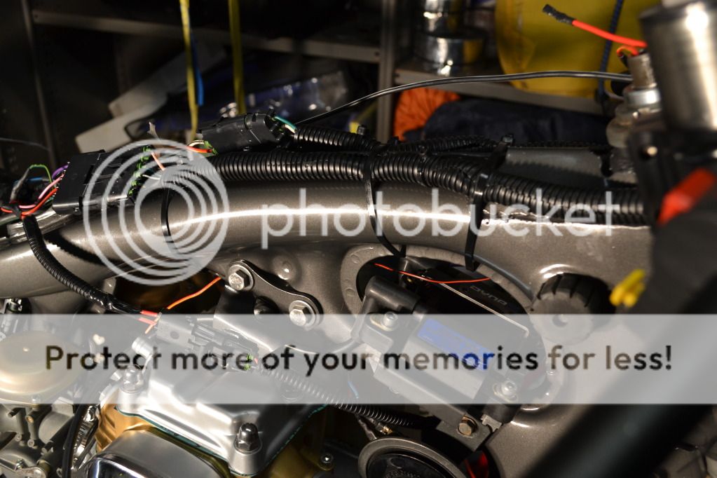
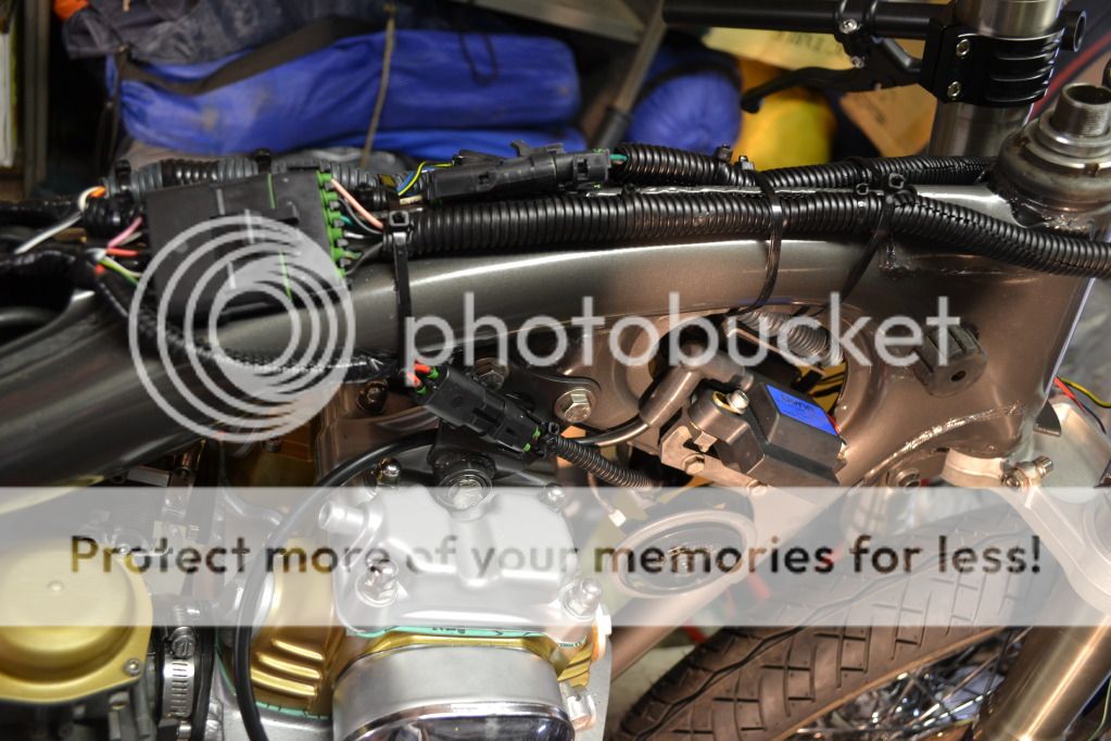
Anyway….here's an update. Half the time was spent trying to make sense of the original wiring diagram. This is the diagram that has some positive wires in red and some in black!! First I worked out where I needed wires to go and ended up with wires all over the place. Then I started working out how to tidy it all up. It's easy really. Measure, cut, feed through frame, strip the end, crimp on the connector, solder, apply heat shrink, cover with cable routing tubing, secure with cable ties. Then undo it all and re-route it somewhere that looks "better". Repeat 15,000 times...
Battery box/rear section all wired and tidied up.
This left the front needing a little love
Front done more or less
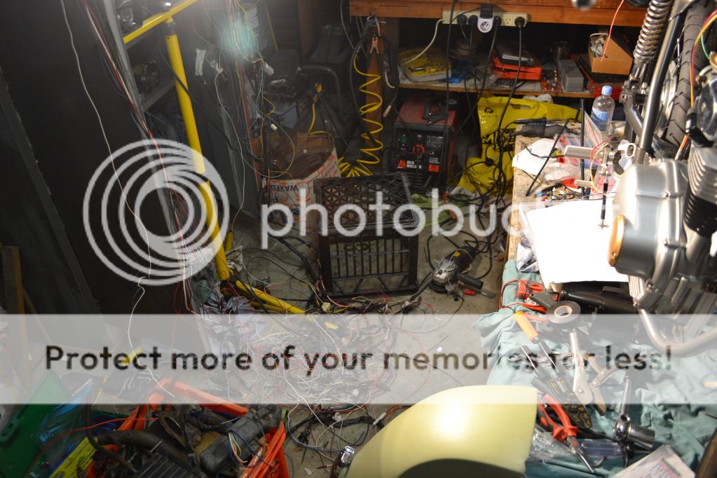
Leaving my garage looking like this…
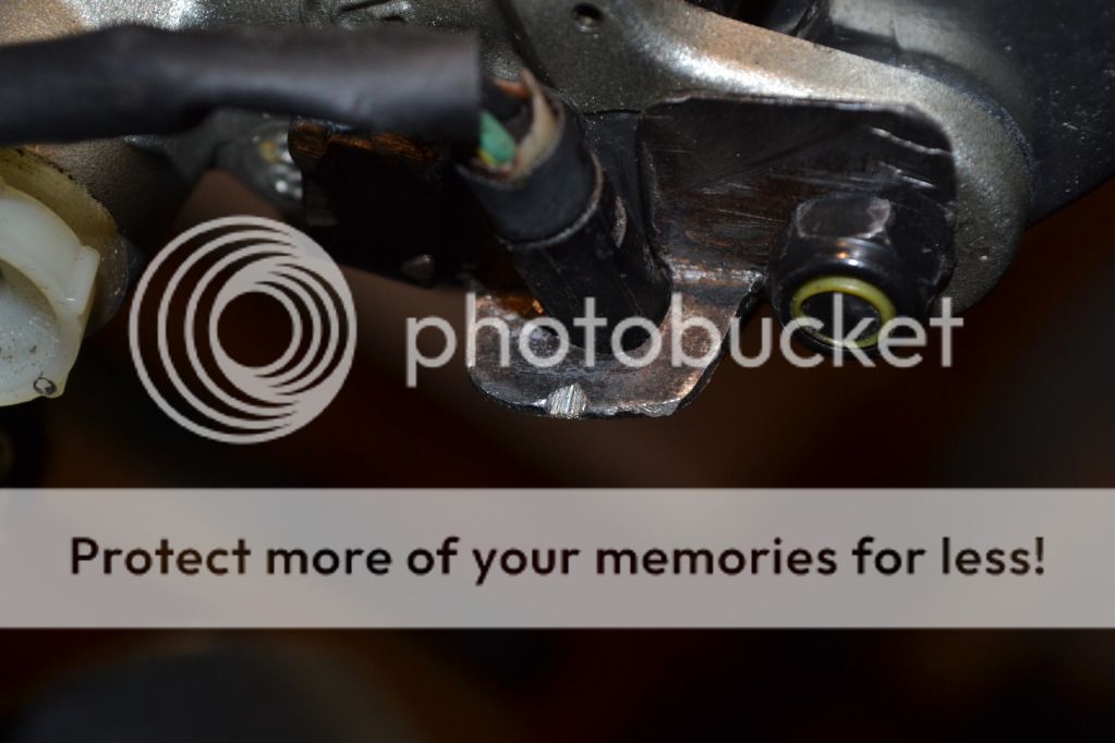
Believe it or not this little bracket to adapt the CB350 front brake switch to the 848 master cylinder took me about 2 hours to make. In the same way that wiring is not my strong point, it appears that metal fabrication isn't either. Sometimes I'm left wondering what my strong point is!?!
I want to have the ability to switch my head light on or off but since I'm using the 848 left switch block, there is no on/off switch, only hi/low beam. So i decided to put my own on/off switch into the circuit. It will be a push button on/off mounted in the top of the steering stem locking nut with the wires running throughout the steering stem and emerging below the bottom triple clamp. Just have to find a 16mm drill bit to drill the top of the big mofo nut. 8)
Maybe it's just me… I never really understood electrons. They're too small. And too negative. I like to stay positive and not surround myself with such negativity. Maybe that's why it's taken me so long. :Anyway….here's an update. Half the time was spent trying to make sense of the original wiring diagram. This is the diagram that has some positive wires in red and some in black!!
First I worked out where I needed wires to go and ended up with wires all over the place. Then I started working out how to tidy it all up. It's easy really. Measure, cut, feed through frame, strip the end, crimp on the connector, solder, apply heat shrink, cover with cable routing tubing, secure with cable ties. Then undo it all and re-route it somewhere that looks "better". Repeat 15,000 times...Battery box/rear section all wired and tidied up.
This left the front needing a little love
Front done more or less
Leaving my garage looking like this…
Believe it or not this little bracket to adapt the CB350 front brake switch to the 848 master cylinder took me about 2 hours to make. In the same way that wiring is not my strong point, it appears that metal fabrication isn't either. Sometimes I'm left wondering what my strong point is!?!
I want to have the ability to switch my head light on or off but since I'm using the 848 left switch block, there is no on/off switch, only hi/low beam. So i decided to put my own on/off switch into the circuit. It will be a push button on/off mounted in the top of the steering stem locking nut with the wires running throughout the steering stem and emerging below the bottom triple clamp. Just have to find a 16mm drill bit to drill the top of the big mofo nut. 8)
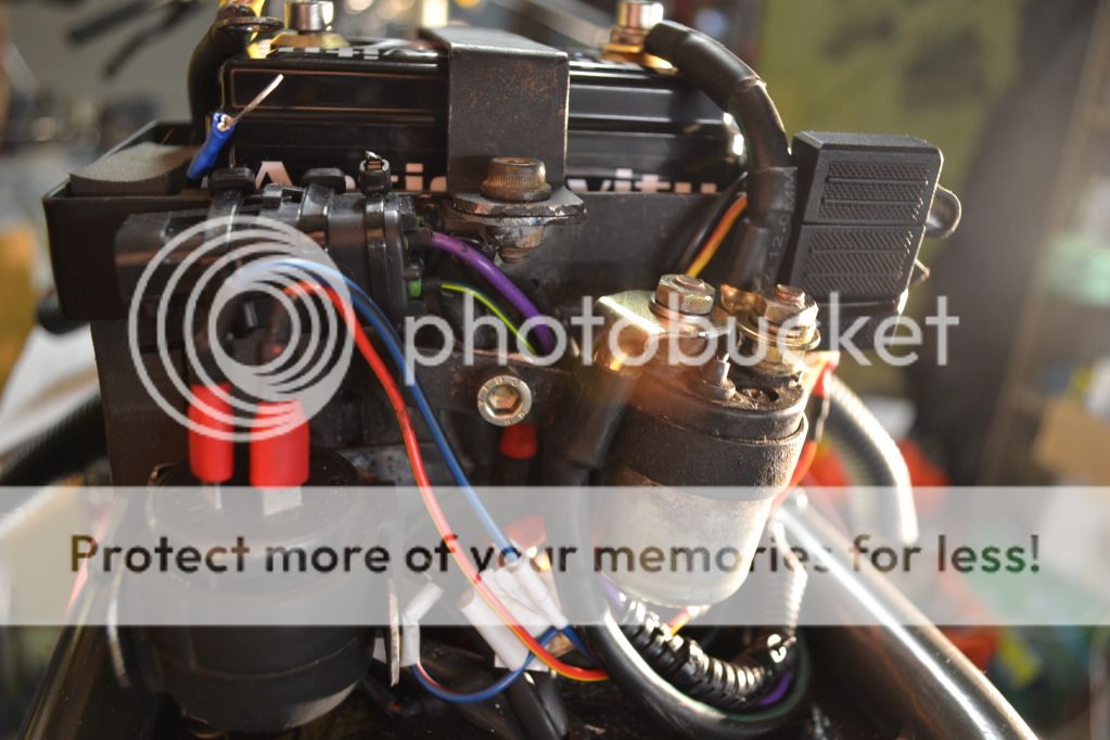
Funny thing happened in the garage yesterday. While I was making the wiring loom I had the negative terminal of the battery disconnected for safety reasons. Then I connected it up and switched the key on to check that various points of the system were getting power when they were supposed to. Because I don't have my "ignition on" idiot light wired up yet I forget that the battery was connected and the key on while I was getting on with the next job. My son happened to come into the garage and was playing around and pressed the starter button. The starter motor instantly sprang into life spinning madly and confirming for me that the solenoid switch, starter motor and starter circuit are all functional. I had a minor heart attack when the starter started spinning because there is no oil in the motor. Didn't take long to realise that the engine wasn't turning over because the starter chain is not on the cog because I had the starter motor off the engine when I was putting the engine in the frame as it makes the installation easier. I had bolted the starter motor back on but still need to get under the left side cover to connect the chain up.
deepwaterimports
Over 1,000 Posts
hahaha the floor looks like a wiring nightmare. you can do mine if you like mate nice job 30hr's would be painful but it was well worth it in the long run as it looks great.
Deepwater, I think I would run a mile before taking on another wiring project. Soooo tedious and slow. I'm very satisfied though to have got it done and to have it all work now. And first go!! 8) 8)
When I said the wiring was finished, of course I didn't mean TOTALLY finished. Just meant pretty much mostly finished except for the bits that weren't finished.
BUT NOW it really is completely totally done. Nothing left to do. Lights, starter motor, starter button, indicators, idiot lights, instrument lights, regulator/rectifier, front/rear brake switches, battery, solenoid etc etc
Not many photos to show but here's a couple of the way the headlight bucket looks. I wanted some fancy bright little LED idiot lights which I bought from Jaycar electronics. Green for neutral, 2 x orange for indicators and blue for high beam.

The thread on each LED is not quite long enough to reach through the surprisingly thick plastic of the headlight bucket so I had to grind a well around each hole with the dremel so I could screw the nut on

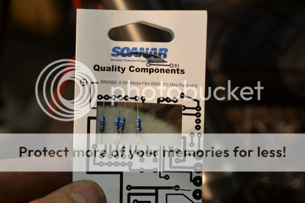
To avoid the LED going pop when connected to 12 volts one of these resistors has to be added into the positive wire on each light.
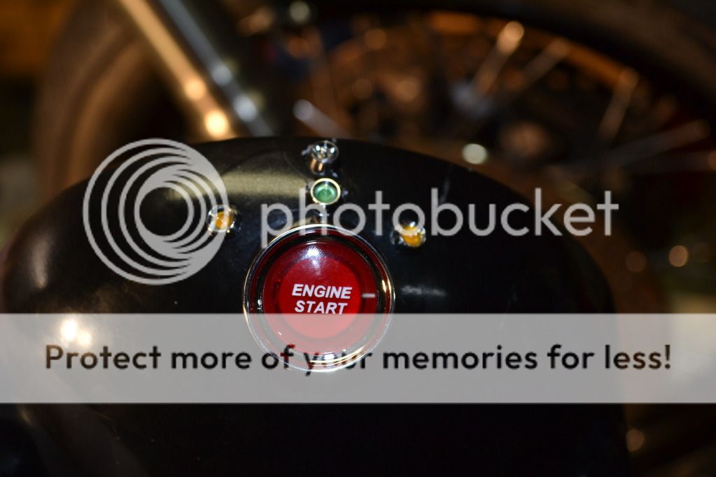
I found a great engine starter button to use on the headlight bucket instead of the right switch block.
All the lights now in place between the "Veglia" instruments
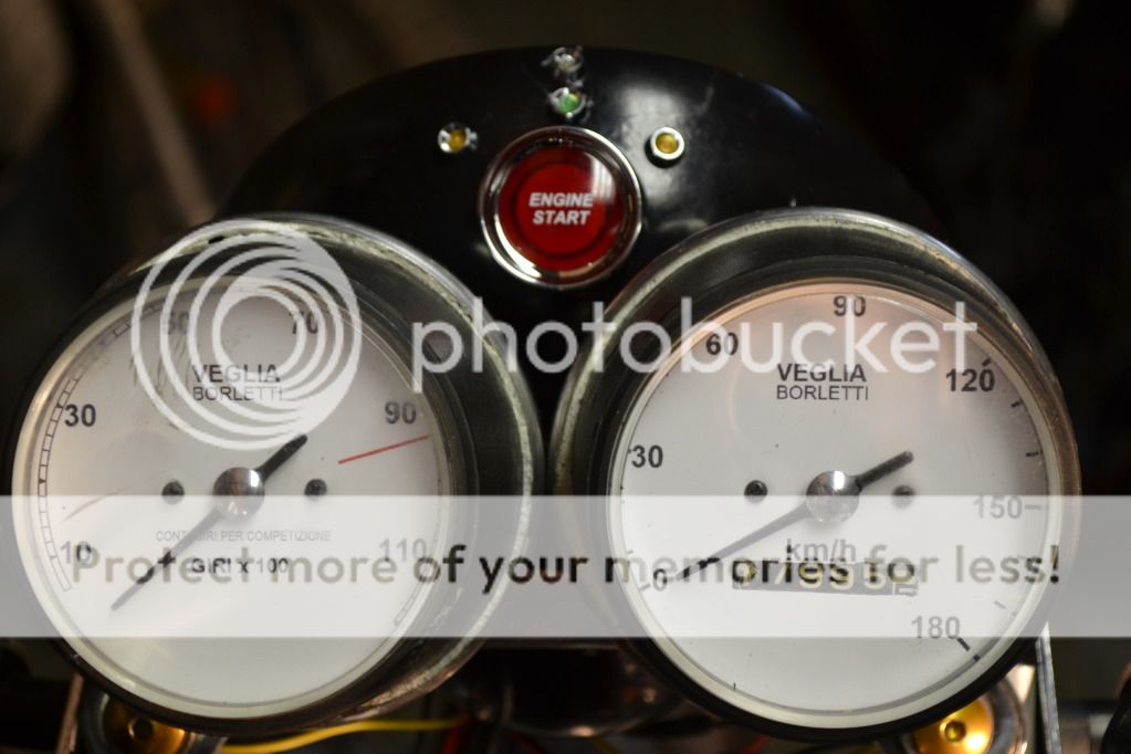
I can't wait to get the odometer to 20000km so the ugly looking 1 will turn over into a 2!!
Now here's a question for any smart electrical boffins out there. I want the engine start button to light up when the ignition key is switched to the 'on' position and then to go off when the engine starts. Where should I pick up the live wire from to power the light in the switch so the light will go off when the engine starts? Anyone know?
When I said the wiring was finished, of course I didn't mean TOTALLY finished. Just meant pretty much mostly finished except for the bits that weren't finished.
BUT NOW it really is completely totally done. Nothing left to do. Lights, starter motor, starter button, indicators, idiot lights, instrument lights, regulator/rectifier, front/rear brake switches, battery, solenoid etc etc
Not many photos to show but here's a couple of the way the headlight bucket looks. I wanted some fancy bright little LED idiot lights which I bought from Jaycar electronics. Green for neutral, 2 x orange for indicators and blue for high beam.
The thread on each LED is not quite long enough to reach through the surprisingly thick plastic of the headlight bucket so I had to grind a well around each hole with the dremel so I could screw the nut on
To avoid the LED going pop when connected to 12 volts one of these resistors has to be added into the positive wire on each light.
I found a great engine starter button to use on the headlight bucket instead of the right switch block.
All the lights now in place between the "Veglia" instruments
I can't wait to get the odometer to 20000km so the ugly looking 1 will turn over into a 2!!
Now here's a question for any smart electrical boffins out there. I want the engine start button to light up when the ignition key is switched to the 'on' position and then to go off when the engine starts. Where should I pick up the live wire from to power the light in the switch so the light will go off when the engine starts? Anyone know?
axeugene27
Over 1,000 Posts
that engine start button looks awesome. I just kick mine


