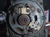
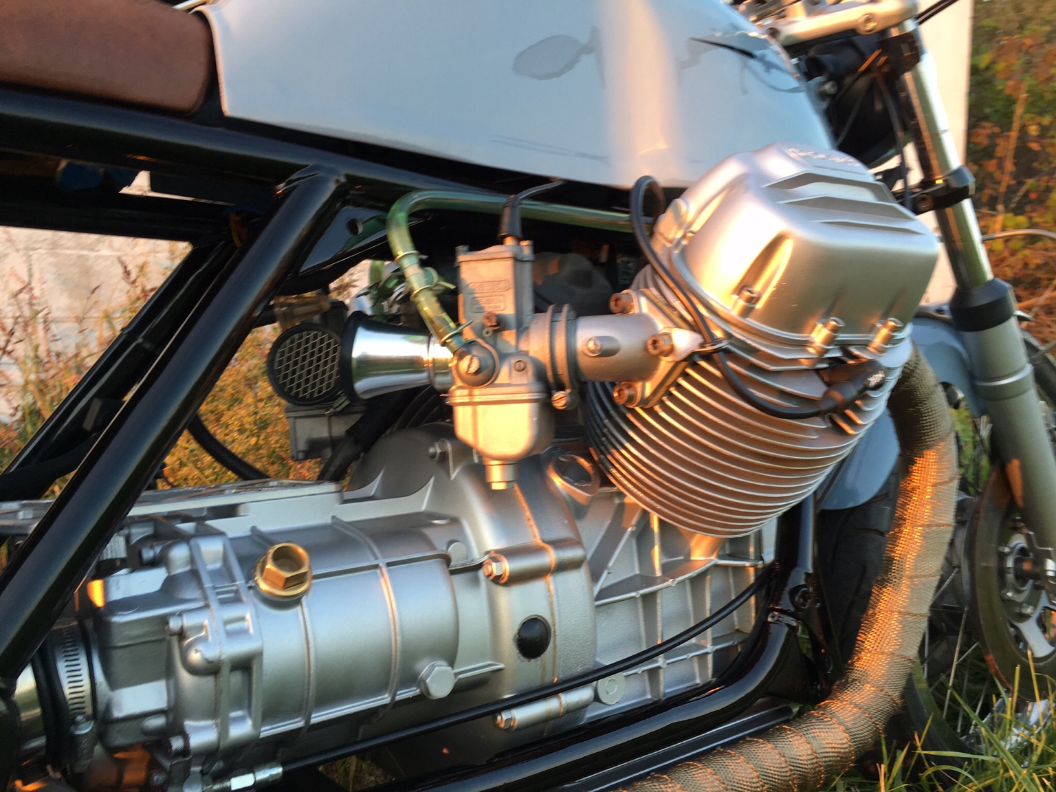
You have the same confusing setup as my Guzzi, same Rectifier/alternator, the two yellows go to the rectifier and the red goes directly to the battery. Which isn't what I'm used to seeing on other bikes I've worked on. I asked for advice about this, and got the following answer..
''The control device can be anywhere in the circuit, here it's between chassis and each yellow wire connected to a rectifier inside the regulator. When the yellow wire goes Negative the rectifier clamps it to the chassis which forces the center tap (red wire) to go Positive and push current to the battery.
Half a cycle later when the other yellow wire goes Negative, it's rectifier again forces the center tap to charge the battery.
This idea was very common in old tube radios.
In this arrangement each coil only works half the time
In this case the rectifiers are not just common diodes they will be Silicon Controlled Rectifiers that can be turned off when the battery is up to Voltage effectively breaking the circuit''.
Which is a bit over my head lol... but I take from this that rather than the current from the alternator, being rectified by the rectifier before it continues on to charge the battery, instead in the Guzzi set up, the rectifier (via the two yellow wires) control the current in the alternator causing it to be rectified at the source (ie the alternator) so the current can go directly to the battery vi the red wire.
Also note that the ground wire to the regulator is very important, ground it to a bolt or screw on the engine.