We noticed you are blocking ads. DO THE TON only works with community supporters. Most are active members of the site with small businesses. Please consider disabling your ad blocking tool and checking out the businesses that help keep our site up and free.
You are using an out of date browser. It may not display this or other websites correctly.
You should upgrade or use an alternative browser.
You should upgrade or use an alternative browser.
1948 HRD Vincent -Ashtray to Driveway
- Thread starter brt651
- Start date
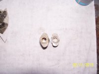
A profile picture of two of the available cams for HRD Vincent engines. The one on the left (Mk 2) is a lightning cam. As in what was used in the Black Lightning. The one on the right is a Mk5 which is used with curved cam followers v's flat with the Mk2. I'll dig some out and take pictures of the differences.
Attachments
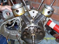
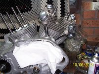
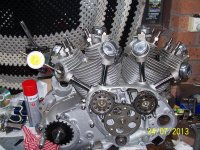
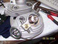
Next up I have become quite creative with yellow outline boxes. In this photo is the valve decompression linkage system. It took a lot of hours to get this to work. With the Mk5 cams its leaves very little room for the actuator arms to work . After careful grinding if the arms it's possible to get them to work. Hours = about 5 hours. Frustrating but worth it.
Oh by the way both heads and barrels are on now.
Oh by the way both heads and barrels are on now.
Attachments
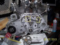
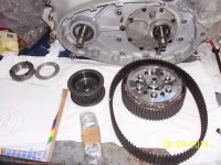
The primary drive system from the ''C'' series engine . High lighted is the compensator section. It has smaller springs inside of the larger springs shown. I'll be installing this set up on engine 2. I have new springs ,chain and spring plate.
For engine one I'm using a Bob Newby belt drive. Yes I'm going to install a plate and seal to the primary side of the crankcase housing with a seal in it. I'll show that when I do it.
For engine one I'm using a Bob Newby belt drive. Yes I'm going to install a plate and seal to the primary side of the crankcase housing with a seal in it. I'll show that when I do it.
Attachments
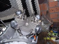
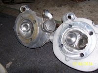
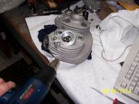
A comparison of a STD 500cc cylinder head to the new 600cc TP head. Note twin plug holes.
Also the valves have two guides. a lower and an upper. The valve rocker engages the valve at mid point. The valve spring sitting on the upper guide.
Also the valves have two guides. a lower and an upper. The valve rocker engages the valve at mid point. The valve spring sitting on the upper guide.
Attachments
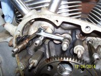
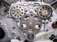
This is the start of timing the cam chest. The followers have to have clearance first ,for the higher lift cams. Then all the followers need to be shimmed.
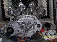
The half time pinion on the crankshaft has 5 slots for timing. Each slot 1.5 deg different. this gear also comes in 10 different sizes. in 2 thou increments from -10 thou to + 10 thou. Why, I'm glad you asked. The idler is on a movable mount. At completion of assembly you need to have zero clearance on all the gears when cold. So start the cam gears on to the cams by 1/8th of an inch and ensure they are square. Fit both cams. Noting the cam gears aren't keyed. The idler gear has 15 deg between each tooth. install idler gear on mount and push it up into mesh. Ensuring the gears rotate freely but with out free play. Now that sounds easy right. Not so. As you tighten the 3 nuts on the idler pedestal it moves. Fast forward 2 hours. Now pick the correct half time pinion to match the the idler to have no clearance , yet free to turn. Another 2 hours on.
I won't bore you with the rest unless you need to know. But using the crank 1.5 deg slots and the 15 degrees from the cam idler lets you get the rear cam close. Then pressing on and of the cam wheel and using a dial gauge and degree wheel you set up the rear cylinder. Then add 50 degrees and another 360 degrees and you do the front cylinder. This time you cant use the crank pinions 1.5 degree slots for adjustment as you will alter the rear cylinder. Any way 40 hours later it should look like this.
Attachments
whata fascinating motor! must take craftmanship to reassemble that beauty!
TessierAshpoolSA
New Member
I really enjoyed your photo essay. Thanks for sharing your insight
The standard cam lobe is about 9mm lift I think. The new Mk5 cam is 11 mm on inlet and 10.5 mm on exhaust.
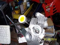
This means I needed to check rocker travel in order to see if I needed to machine anything away to give me the travel required. The new heads allow for extra travel , though I did have to modify the upper valve guide for clearance. In the following pictures you can see me checking rocker travel and also the rocker actuating on the valve. I have left out the upper valve guide for this picture.
This means I needed to check rocker travel in order to see if I needed to machine anything away to give me the travel required. The new heads allow for extra travel , though I did have to modify the upper valve guide for clearance. In the following pictures you can see me checking rocker travel and also the rocker actuating on the valve. I have left out the upper valve guide for this picture.
Attachments
Hello Again,
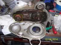
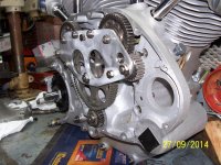
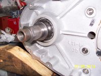
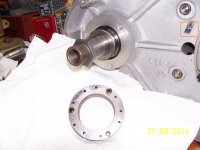
Firstly because I'm fitting a belt drive and secondly this was a modification done by the factory in around 1951 on the 500. I'm fitting a seal and I need a seal holder. The seal holders I have are the genuine style. But, I have a back to back Timken Taper bearings fitted to the left side of the crank. Originally it has a ball bearing outer most ( which controls crank end float) and the other three crankshaft bearings are roller type. I show the area in the photos, along with my drilling guide and seal holder. I'm not going to use this seal holder as I want it to place some pressure against the taper bearing cup and come outwards from the bearing as well. As I have more clearance with the belt drive than I would if I where to use the original chain primary drive. And since I have 2 engine with this set up I'll be getting 2 made.
And for those that notice the orange square outline. This is a marking that is stamped into the cases. To check that they are a matched set. Very hard to see. But this unique marking is in the 2 crank halfs,primary cover ,G2 cover. I don't know what the stamping means. Maybe the bloke that assembles the engine has his own stamp?
Well this is as far as I've got. I''ll get some more pics up as I get more done. Off to lap the pushrods in.
Cheers
brt651
Attachments
Habanero52
The Race......is only with yourself!
What a beautiful engine!!! Great job man.
Hello,
Well I have the Bob Newby belt drive out and measuring for new distance spacers and a new seal holder. I've been in contact with my machinist and he is up to speed. So its all go ahead.
then I need to make a new primary cover. I have seen some out of fiberglass ,but they look a bit ordinary. It needs to be alloy and polished. Anyone have one?
Well that means back to the timing side to finish of the push rods.
Have a great week