Vintage Speed Part Mashup - 1976 CB750F

I received the tastiest of packages from our friend and JMR Porting, which includes a stage IV head that shines like a jewel, as well as a Wiseco 836 kit and some Cycle X rods. It was a big cash layout but I know it will be well worth it in the end. The upsides is that the largest single outlays of cash should be behind me as I work from the top down on this engine build.

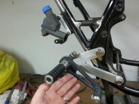
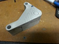
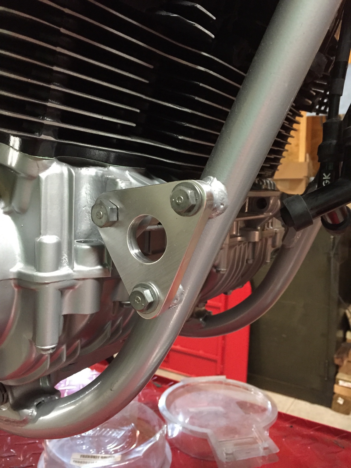
As I get going on the build again, I have turned focus to a few nagging items. First is getting all the aluminum parts that I have made ready for hardcoat anodizing. I am sold on hardcoat simply because it is not a decorative finish like regular anodizing, and since most parts would be black anyway, it seems like a no brainer to go with hardcoat, enhanced with black dye. Parts that will be black hardcoat include the rear caliper mount, rear master cylinder mount, all front brake mounting brackets, the Weber intake, rearset brackets, and engine mounts both front and rear.

I had to pull the engine to do a leaky head gasket which is now done, so its time to finish up the frame by getting all the gusseting/bracing finished up and mounting the AP Racing rear master. Once I get some paint on to cover the exposed areas, I can continue my mock up build. My plan is to get this thing vetted over the next year before I go to final paint/powder. I hear of too many guys who build their dream bike in one go then remember that one bracket that costs them days of downtime and new powder on the frame.

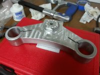
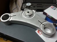
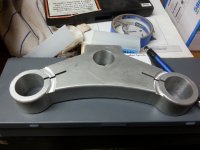
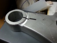
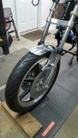
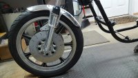
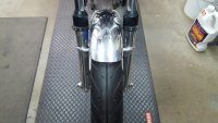
For the front end, which is shaping up to be my favorite part of the bike, the only thing left is axle spacers. Those too will be black hardcoat anodized. Beyond that I will need to figure out what to do with brake lines. I can either do two full-length lines from the master to each caliper, or do one short one to a splitter and a line to each caliper from there. Finding a place to mount the splitter that doesn't clutter things up is my main concern. Probably going with two full-length lines.

On the rear, I have powder on the Marzocchi shocks, and the rebuilds are ready to go in with fresh oil. All that is holding that up is getting a few pieces refinished, like the adjuster collars and top spring retaining collars. This damn hardcoat anodizing is causing quite the bottleneck in my project!

Other things to button up are getting some upholstery on my seatpan and getting the tank cover, seat in at least the same color of primer so I don't look like a complete idiot.

Though the list is long I am shooting to get a rideable bike before the sun sets on summer here in Michigan.
 
I finally got the rear master mounted on its bracket and the tab welded to the frame. I have a parts order in at Fast From the Past for some linkage parts to complete the assembly.

I will also be picking up the front wheel spacers from the machine shop today, which should complete fabrication on the front end. I will also be dropping off the stainless rod for the engine mounting bolts, which will be threaded and fitted with 12pt ARP nuts. One end will be welded like a bolt head to its less of a cumbersome assembly.

The last pic is the rear motor mount. It is a riff on the one Doctor D has on his bike. I am still working on the design and may have another one water jetted before it goes out for machining.
 

Attachments

  • 20150617_201229_resized.jpg
    20150617_201229_resized.jpg
    1 MB · Views: 317
  • 20150617_201243_resized.jpg
    20150617_201243_resized.jpg
    1.1 MB · Views: 319
Well, I am officially at the next level of fabrication! I just got my mill set up in my garage and started modifying my top triple clamp to better reflect my vision for it. This opens up a whole world of opportunity for this build and any future projects.

I will also be getting my 8x16 lathe set up in my basement in the next few weeks.

My head is literally spinning with ideas. The first major task I am taking on is getting a jig built to replicate a Seeley swing arm for this bike. I know that I already have the Dresda copy but I want to have options, don't I?! I already have most of the raw material for the arm itself but need to design a plate for the hold down fixtures.

I have a variety of other things I want to tackle as well, and once I am up and running, I will be offering services here, with an initial focus on custom triple trees. I know there are already quite a few options but my focus will be on the one-off market. The guy who has looked high and low for something especially unique will be my target.

At any rate, here are a few pics of my work last night.
 

Attachments

  • 20150816_214715.jpg
    20150816_214715.jpg
    1.9 MB · Views: 322
  • 20150816_210840.jpg
    20150816_210840.jpg
    1.9 MB · Views: 335
  • 20150816_190642.jpg
    20150816_190642.jpg
    2 MB · Views: 343
  • 20150816_190634.jpg
    20150816_190634.jpg
    1.3 MB · Views: 332
I figured I would bust out a quick update so everyone knew this thing was still moving forward. I was fortunate to get some time in the shop this weekend and wanted to start ticking things off the list, and the fender was it.

I had been trying to figure out how to line everything up and mark the fender for the mounts, knowing that I basically had one shot. Yes I could weld up the holes and try again, but getting it right the first time was the goal.

I started by mounting the Y brackets to the top part of the caliper carriers so the orientation and location was locked in. After that the fender could be positioned and marked, then drilled. The hardware is simple button head screw for now but will be replaced with ARP 12-pt bolts to tie into the rest of the build.

The last thing is to fit the Y brackets around the caliper mounts a little better for a more finished look.

So far, it has turned out exactly as I envisioned and really looks like a front end from a 60's/70's British bike.
 

Attachments

  • 20151101_201339_resized.jpg
    20151101_201339_resized.jpg
    1.3 MB · Views: 328
  • 20151101_201356_resized.jpg
    20151101_201356_resized.jpg
    1.4 MB · Views: 326
  • 20151101_201406_resized.jpg
    20151101_201406_resized.jpg
    1 MB · Views: 329
Tune-A-Fish said:
Trick fab work, Dang people that have machines and I have is a drill and a set of files :-[

Any trick bits you need for a project, let me know. I can at least help get them designed and rough cut using water jet. That will save a ton of hand work.
 
Coolest instrument mount I have seen. I have a similar concept planned for a headlight mount - hope you don't mind I steal your design and incorporate it with my own! I reckon everything has been done before somewhere, but this is a great looking project!
 
jpmobius said:
Coolest instrument mount I have seen. I have a similar concept planned for a headlight mount - hope you don't mind I steal your design and incorporate it with my own! I reckon everything has been done before somewhere, but this is a great looking project!

I spied that also, makes for removing it intact nice. I might suggest a through hole in the tree with small rubber bushings to soft mount it and maybe dampen some vibration?
 
slikwilli420 said:
Any trick bits you need for a project, let me know. I can at least help get them designed and rough cut using water jet. That will save a ton of hand work.

Than you sir!

I am the guy who takes those offers seriously. I am just completing a 72 CB750 modified, I designed an oil tank with AN fittings and one is in the way causing me to have to move my right rear motor mount bracket from inside direct to motor out to the outside and use a spacer, I have made one to match the front from 6061 plate, but need the spacer.

What would be really trick is to mill it out of chunk of billet as a one piece unit with inside cut similar to yours with radius around the spacer portion. $$?? Don't quote this post so I can delete it so that your build is not cluttered up with my junk.

Front mount, drill and file version:

ed05fbd97725622693941b46006a4b61.jpg
 
jpmobius said:
Coolest instrument mount I have seen. I have a similar concept planned for a headlight mount - hope you don't mind I steal your design and incorporate it with my own! I reckon everything has been done before somewhere, but this is a great looking project!

Thanks for the props! I will definitely take tune a fish's idea about a rubber mount to dampen vibration. I wanted something totally unique from other mounting options I have seen.
 
Tune-A-Fish said:
Than you sir!

I am the guy who takes those offers seriously. I am just completing a 72 CB750 modified, I designed an oil tank with AN fittings and one is in the way causing me to have to move my right rear motor mount bracket from inside direct to motor out to the outside and use a spacer, I have made one to match the front from 6061 plate, but need the spacer.

What would be really trick is to mill it out of chunk of billet as a one piece unit with inside cut similar to yours with radius around the spacer portion. $$?? Don't quote this post so I can delete it so that your build is not cluttered up with my junk.

Front mount, drill and file version:

ed05fbd97725622693941b46006a4b61.jpg

Send me a PM and we can swap info and discuss some ideas. I have a full thread on custom triple trees over at the SOHC4 forum to give you some ideas of what I can do. I love designing parts for these machines so I'm happy to help.
 
Not a very exciting update, but trying to get things marked off the punch list. I have been exploring ideas to give the brake discs a little something extra, and have landed on an additional set of holes in the inner perimeter of the disc and some cuts to the carrier itself. It gave me an excuse to use my rotary table, which is quickly becoming one of my favorite tools.
 

Attachments

  • 20160128_202053.jpg
    20160128_202053.jpg
    103.5 KB · Views: 316
  • 20160128_202101.jpg
    20160128_202101.jpg
    104.6 KB · Views: 317
Your builds and CAD design work, access to local water jet cutting shop, and now your milling/lathe work are nothing short of spectacular... This build is great. I may be using your assistance to do more than just the three billet aluminum parts we're already talking about... Looks awesome.
 
Thanks guys. I love designing parts and tweaking existing designs to suit my needs. Custom parts are a huge necessity when trying to adapt things for new applications and that's one of my very favorite parts of this hobby.
 
So the rotary table must be a clamping table for the milling machine that spins the part being machined slowly so you can mill radiused cuts into it? Sounds like I really need to get a good used lathe, maybe a harbor freight milling machine, and a rotary table one of these days... the water jet shop and your CAD skills really make an awesome substitute for access to a CNC machine.
 
The rotary table is super useful for a ton of parts fabrication work. I highly recommend one for anyone getting into custom parts. The access to CAD and water jet machine is very beneficial vs a CNC mill. It takes more finish work but the parts have a more organic hand made feel I really like.
 
Back
Top Bottom