74 RD350 - Anything more than 2 strokes is a waste

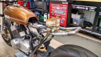
Nothing too wild going on with this bike right now. It's a lot of detail work that takes a shitload of time for very small sized results. I guess it's when you add up all of these little jobs that the big results come.

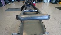
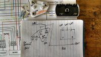
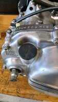
1. I wanted a clean way to get my battery and tail lamp wire through from the harness to the rear of the bike. So I added some 1/2" OD "conduits" through the existing lateral frame section. I would have liked them to be further outside, but that was as close as I could get the right angle drill in there.

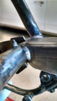
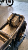
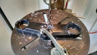
2. I had only tack welded the suspension mounts, frame gussets, and everything else on the frame. Reason being is that I wasn't 100% sure on geometry, fitment, yada yada. Well, nothing has caused me to make a change since originally tack welding everything together in August so I sealed the deal tonight and finished welding everything on the frame. Man I miss having that TIG welder around...

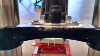
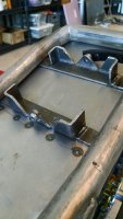
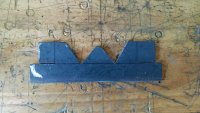
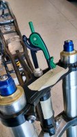
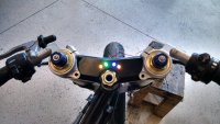
3. My bolt on steering stop had a good bit of flex with only a single piece of .083" as the mounting plate. Last week,before the TIG was returned, I added a second layer of .083" plate to the base and got that installed. Much improved.
 

Attachments

  • IMG_20150331_152637135.jpg
    IMG_20150331_152637135.jpg
    2.9 MB · Views: 265
  • IMG_20150331_190905102_HDR.jpg
    IMG_20150331_190905102_HDR.jpg
    3 MB · Views: 256
  • IMG_20150331_190636044_HDR.jpg
    IMG_20150331_190636044_HDR.jpg
    3 MB · Views: 263
Have any of you fellas completed the windmill rectifier and Delco voltage regulator upgrade to your RD250/350? I've been digging through posts at 2SW on this topic and can't find a definitive answer. Some of the old 10SI alternator wiring diagrams I've dug up aren't the clearest either. Anyway, if you anyone has input on this topic, please chime in. I'm looking for confirmation that I have this wiring diagram below routed properly. Thanks.

Rectifier - the 3 white AC wires coming from each stator winding.
Out of the rectifier + is the red wire. Red wire to battery and the D+ pole of the regulator.
- terminal is not used to run rectifier in half wave

Regulator - D+ gets the red wire from the battery/rectifier.
FLD is the green wire that goes to the generator brushes
GND is ground. Black wire to frame.
L is switched 12V. Brown wire. I believe this opens/closes the regulator circuit as to not drain the battery when the bike is OFF.
 

Attachments

  • IMG_20150403_120056797_HDR.jpg
    IMG_20150403_120056797_HDR.jpg
    3.6 MB · Views: 248
Well I finally buckled down and bought a battery. Instead of dropping $140 on a Li-Ion small/light unit, I picked up this little guy from McMaster Carr for $26. It came recommended from a friend with an RD after having gone through some issues with not having enough A-h.
So then I had to mount it. I fab'd a battery mount system to sit behind the seat in the tail section. I didn't want the weight of the battery (6lbs) being held by the seat pan. I made it out of 1/8" steel so I could weld it to the tail hoop. My left bicep is getting considerably bigger than my right bicep from all of the hacksaw work this bike is requiring.
 

Attachments

  • IMG_20150409_180223885_HDR.jpg
    IMG_20150409_180223885_HDR.jpg
    1.1 MB · Views: 251
  • IMG_20150409_173329883.jpg
    IMG_20150409_173329883.jpg
    3.3 MB · Views: 276
  • IMG_20150409_152333588.jpg
    IMG_20150409_152333588.jpg
    3.8 MB · Views: 294
  • IMG_20150409_135244304.jpg
    IMG_20150409_135244304.jpg
    3.1 MB · Views: 283
So I got motivated this morning and knocked out a few details that have been bugging me.

My trans oil dipstick had 3/4 of the "lever" broken off. So I cut the remainder off, added a slot, and sanded. I'll hit it again when I have some sandpaper finer than 400 grit.

I don't have any plans for a gauge cluster (for better or for worse). I got the idea to mount some LED's for L, N, H, and R.
 

Attachments

  • IMG_20150410_091701221_HDR.jpg
    IMG_20150410_091701221_HDR.jpg
    3.2 MB · Views: 237
  • IMG_20150410_095409266_HDR.jpg
    IMG_20150410_095409266_HDR.jpg
    1 MB · Views: 282
  • IMG_20150410_101357442_HDR.jpg
    IMG_20150410_101357442_HDR.jpg
    3.1 MB · Views: 255
  • IMG_20150410_103638187_HDR.jpg
    IMG_20150410_103638187_HDR.jpg
    1.2 MB · Views: 259
As far as the bicep getting bigger, flip the hacksaw blade around and work on that tricep a little bit. The push/pull split of a motorcycle man.
 
Speaking of biceps, check this out. One of the coolest documentaries I've seen. A must see for those of us that enjoy working with our hands. This guy built everything by hand and lived alone in Alaska for 30 years. A man's man.
https://youtu.be/iYJKd0rkKss
 
So my second attempt at a fiberglass front fender. The first one was laid in January, took 2 weeks to cure, and looked like shit. Take 2 came out the way I wanted...but is too wide to fit between the forks. Its also about twice as thick as needed.
Option 1 is to trim it until it fits. Its the easy route that I'm sure will end up fucked up.
Option 2 is to use Option 1 as the mold and glass a proper sized front fender.
Either way, I have no idea what the fuck I'm doing with fiberglass aside from digging splinters out of my hands

f5002be1ccef45f272c7128d54fe23bc.jpg

bf1a9770c2ee6924ac7c2bca7650d52f.jpg

e8ae5392dbfd57c223abcdb0df02d160.jpg
 
I did the smart thing and used the original fender as a mold. Its still in the mold and fitment is TBD.

I also went to work on laying a fiberglass seat and tail section. I put down 2-3 layers this morning. I'm going to let that cure and essentially use it as a bit of a mold for the last 2 layers. There are some spots below that frame rails that don't have much support behind them, so I had to go easy when wetting those areas. The temps are a little cool here so the curing process may take a little longer, although I mixed the resin a little hot to account for it.

24c388c513fbc917b4e64aae4c1651b7.jpg

09dccbe0b2c39456c9db69803d164b27.jpg
 
Not sure if I'm feeling this or not. I'm kinda mad at myself for not walking away from it when it was still styrofoam. I had a plan in my head of what I wanted this to look like...this isn't it.
I'm going away for a few days to head to the NY/NJ supercross. Maybe I'll find a moment of clarity and make a decision on what comes next.
 

Attachments

  • IMG_20150421_072024777[1].jpg
    IMG_20150421_072024777[1].jpg
    3.8 MB · Views: 259
  • IMG_20150421_072106043[1].jpg
    IMG_20150421_072106043[1].jpg
    3.4 MB · Views: 234
Just personal opinion, but I think it would look worlds better without the front bump that goes up the back of the tank. Other than that, I like it.
 
7aliveatlast7 said:
Just personal opinion, but I think it would look worlds better without the front bump that goes up the back of the tank. Other than that, I like it.
I totally agree!
 
Thanks for the comments fellas. I added that section directly behind the tank as a means to bridge the gap between the back of the tank and the seat. I didn't plan to have the seat/foam be tall enough to hide the large gap at the rear of the tank.
When I get back to NC, I'm going to trim down the seat section and see how it looks. I have more fiberglass on the way, so if I have to start all over again I can.
 

Attachments

  • IMG_20150204_185237229_HDR.jpg
    IMG_20150204_185237229_HDR.jpg
    3.4 MB · Views: 222
Well, enjoy the races this weekend. I hope it's not another blah, blah, blah Dungey is in the lead and takes off kind of race.
 
Back
Top Bottom