Project "Vision Quest"

CALfeRacer

Fat man on a little bike
Instead of boring everyone with a long backstory, the short story is that I decided to swap a 86 KX250 engine into a late 60's C2 frame for a class project. I've had the stuff laying around for just over a year now, and making it a school thing gives me an excuse to do it.
This is the only picture I have of the frame before I started. Mocked up with the 86 KX swingarm.
d6e0bd5e09ad7384426b469d95d64895.jpg

Since then I've removed the remaining mounts from the engine area of the frame using a cutoff wheel, plasma torch, and a flap wheel.
4e658e6b72ff50bb78d53c04cc2655f9.jpg

b6f58f6a699b2ce46c6cef683d487e01.jpg

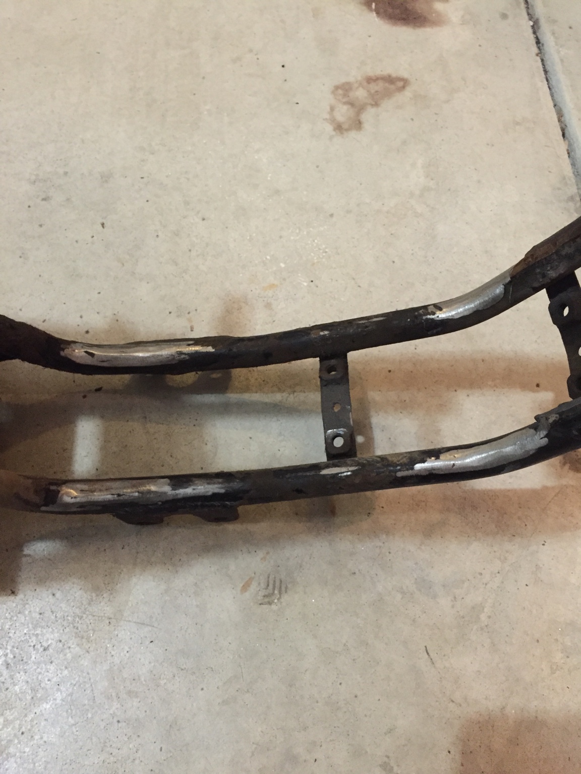
I was having issues with the swingarm pivot getting in the way of the motor. Since I'm probably going to use the KX swinger through the pivot on the back of the motor it was time for it to go away.
68a2c82228b7b9f69a12da85abef96ce.jpg

d9634b6b49563cf6d041ce9377d23154.jpg

ad3a59e05cfba4363e2eac2afbe981ef.jpg

To this:
45612d8f76cf68fc5c92a7f2cf1220ee.jpg


Which brings me to today. I'm trying to figure out how the engine is going to sit in the frame, but I'm not sure on how it should go so I'm posting it here to ask for some advice. The housing for the kicker is limiting me, it hits the frame on the back. Not sure where the swingarm pivot needs to be in relation to the frame since it is a fixed distance from the sprocket (since it's the engine case). I took a shot of two setups which seem decent to me.
d5ec353b4c20b29b2e19d4d0eb4aa2bb.jpg

65846029e530e2cd3585417b53593c96.jpg

These both give decent clearance of the kicker case to the frame, but there's a pretty big gap from the swinger pivot to the frame. Keep in mind these aren't a perfect representation, the frame is propped up and the engine is dropped from where it would be if it was in the frame. AKA the gap between the pivot and frame looks worse than it is.
Any thoughts on how the motor should sit are appreciated, I want to get to making mounts and welding next week. Thanks for checking it out and hopefully there will be more updates soon!


Sent from my iPhone using DO THE TON
 
Re: Project "Vision Quest"

For reference... When the engine is up in the frame the pivot sits about 1.5" from the fame. I took another shot with the swingarm lined up to where the pivot on the engine is:
5126989f2deb90af8b210f9967014211.jpg

It's got plenty of room for a full range of motion from there and the engine seems to sit in a decent place. My main concern is that if the engine is too tilted in one direction or another it'll oil starve or have issues with the cooling system.


Sent from my iPhone using DO THE TON
 
Re: Project "Vision Quest"

I have been wanting to do something like this for a long time but never could. Following along very closely should be awesome.


Sent from my iPhone using Tapatalk
 
Thanks! I've had these laying around for a while (year and a half?) and I wanted to finally get myself to do it, so why not put a deadline on it that has legitimate implications? The goal is to have the engine 100% mounted and the auxiliary stuff (pipe, intake/carb, radiators, etc) mocked up by the end of the quarter (March 22nd?) so I can do my class presentation on it. From there I'll probably slow down again trying to figure out suspension and wheels during spring quarter, depending on how hard classes end up being. Eventually I'll have to buy a lighting coil for it and make a harness to run lights and such... also will eventually need to get the title process done. And a tank/seat setup... But all of that is way off in the future! Engine mounting is what matters right now.

I spent a little bit of time digging through google images and came up with some shots of each donor bike that should help me figure out how the engine needs to sit. From what i can see the "Kawasaki" on the stator cover should be roughly horizontal with the ground, as that is how it sits in the KX. I can also see that the upper frame rail is nearly parallel with the ground on the C2, so I should be able to use it as a reference line for the KX motor. If you look at the pictures, the stator cover label is more in line with the lower frame rail, so I'll need to see how rotating the engine forwards works with the kicker housing being a pain... Progress will be posted tomorrow!
 
Re: Project "Vision Quest"

"Vision Quest".....nice.
Digging the plan thus far. Ill be following along for sure!


Sent from my iPhone using Tapatalk Pro
 
Thanks! I guess a little explanation of the project name is in order.
The class I'm doing this project for is heavily project based, one of which is that each person has to come up with a "Quest" to do over the quarter that is supposed to be something that makes both them and their peers "better." When I first heard that we had to go on a quest I immediately thought of a vision quest in nature... and the name stuck!
 
Re: Project "Vision Quest"

Ah I understand. I thought it was inspired by this, http://m.imdb.com/title/tt0090270/


Sent from my iPhone using Tapatalk Pro
 
Re: Project "Vision Quest"

No, I can't say I've ever seen that movie. Although maybe I'll have to give it a shot haha

I spent some time playing with the engine and doing some arts and crafts this afternoon.
f6af146b32f7707fb1314df9cefad120.jpg

c93a3b312bd768b6ab01ae811d15ee4c.jpg

Looks like I can get the motor to sit about where it should without the kicker housing hitting the frame. The front mounts will be a bit closer than I originally wanted, but it'll work out. As you can see above, I mocked up the front, bottom, and rear mounts with some paper. I'm going to dig through the scrap bin at work this week and see if there's any steel I can snag to cut out the mounts and get it mocked up.
I ran into a slight issue with the rear shock setup that'll need attention but doesn't need to be done for the presentation. The rear shock is way too short, which I anticipated due to the much longer swingarm, but the swinger is also wider which means the shocks don't quite line up.
c623b754a996d1c9c4c946dd47fead0a.jpg

As you can see, the shock sits on the inside of the swingarm about halfway. As I see it, my options right now are to see if there's room for me to space out the shock with some washers and still have enough thread up top or cut off the stock shock mounts and weld on new, longer mounts to space them out enough. I ruled out a mono setup because even though they look cool I think it would just destroy this little frame, which is kind of already a possibility due to replacing a 60's 120cc with an 80's 250cc. Also, the shock is huge and probably wouldn't fit in the frame using the designed uni-trak setup (which I've never seen anything like before). I could see if the CBR shock I have laying around would work, but again I'm afraid it would turn the frame into spaghetti and the spring rate/damping is probably a million miles off from what it would need to be.


Sent from my iPhone using DO THE TON
 
Re: Project "Vision Quest"

Mounts are finally done! I've been super busy so I've been chipping away at them in my spare time. Found some 12 gauge scrap to cut them out with a plasma. Cut the mounts WAY too big and had to spend what felt like a million years grinding them down.
bfd96f10cabce09d2b94a602c7e6dff0.jpg

The bottoms are all left rough because they were made big, so that I can mock them up once holes are drilled and get them to the perfect length.
Hopefully I'll be welding in the next week!


Sent from my iPhone using DO THE TON
 
Back
Top Bottom