
MBellRacing
Wheel Jockey for Hire
I've been getting a lot of requests on specifically how I made the 7 emitter LED high/low headlight for a number of other applications. First off, I want to say that nobody gets it all right the first time on something ilk this. Because of this I want to make sure that people understand that this build was imperfect and there is plenty of room for improvement. The light I made should work quite well for my application, but there are improvements to be made that may better suit each individual bike.
Anyway, I started out with a problem: The CB77 doesn't charge the battery with the headlight on. This is already an issue for a standard bike, especially when law states the bike must have the headlight lit at all times to ride it on the street. My application required even more electricity from the charging system, all while appealing to that previously stated law. My bike was to be electronically fuel injected (build is elsewhere on this forum) so the fuel pump and ECU would require a lot of juice. My stock headlight used up about 25W on low beam and 35W on high beam. Even the taillight used up 10W on it's own! As you will see later and as you build your own LED headlight, incandescent bulbs are extremely inefficient.
At the time of writing this I have completed the build stage for the most part, have done bench testing, but no riding. I do not yet know how it will stand up to vibration or dramatic heat change. That said, the bench tests have netted some impressive results. If there are unforeseen issues in the previously mentioned areas, I'm sure it won't be too difficult to modify the assembly to fix any problems. Here are the features of my current setup:
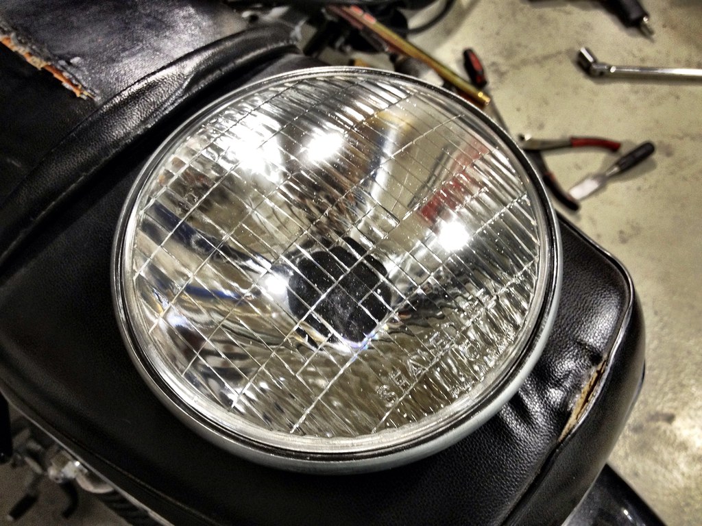
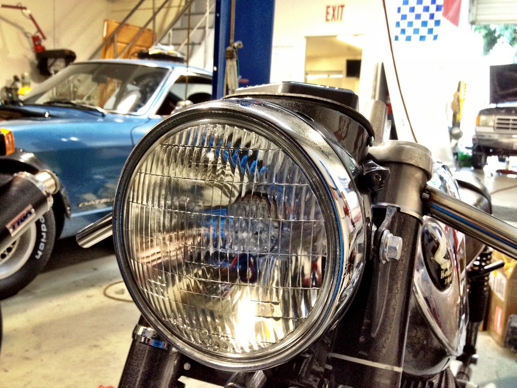
-Looks reasonably like the original headlight
-Uses a maximum of 15W on high beam
-Infinitely adjustable low beam setting, I'm currently using 3W
-Very low heat
-Shines bright white, not yellow
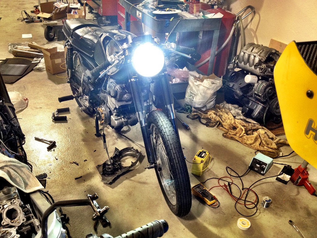
-Light is very intense even on low beam to be seen better.
-Glass still says DOT, a dumb piggy might not know the difference
A quick note on LEDs. They are very efficient nowadays but still create a pretty good amount of heat. On the mounting plate directly behind the LED panel I see about 136 degrees Fahrenheit. This isn't going to cause some nuclear meltdown, but it should be reason to think about getting rid of some of it and making sure that the emitter panel and the required heat sink doesn't get close to anything that can melt. LEDs are not like incandescent bulbs. They cannot just be hooked up to a bike's battery voltage. The high current will cook them. You need a voltage driver to regulate the power supply. LEDs are also very intense but still produce light in roughly 180 degree patterns. They need a lens to focus the light in your desired pattern.
So here's what you need to make the light I created:
-Donor headlight. I bought a cheap knockoff sealed beam unit.
-LED emitter panel. I purchased this one: http://www.luxeonstar.com/Cool-White-5650K-7-LED-40mm-Round-Assembly-p/sr-02-wc310.htm This emitter panel is rated up to 1000mA but I feel it probably creates an inordinate amount of heat at that output.
-DC voltage driver. This one is dimmable for a low beam setting: http://www.luxeonstar.com/700mA-Externally-Dimmable-FlexBlock-Driver-p/a011-d-v-700.htm If you're daring enough to get the emitters up to 1000mA you'll have to purchase the next model up.
-Focusing lens. This one is 50 degree spread: http://www.luxeonstar.com/Polymer-Optics-7-LED-Cluster-50-Optic-p/262.htm This lens puts out a lot of light to the sides and even uses the headlight reflector to send some light in a somewhat natural direction. The same company also sells a 15 degree lens that probably acts more like a car's high beam and will work even more effectively, of course at a sacrifice of some side light.
-Copper sheet. Something bendable works quite well but it needs to support the emitter panel and be able to mount to the headlight reflector.
-Diode. This is half of an anti-reverse polarity protection. It's a 3A 50V rectifier diode and can be found at any electronics store like Radio Shack or here at Digi-Key: http://search.digikey.com/us/en/products/1N5400-TP/1N5400-TPTR-ND/950387
-Capacitor. The other half of the anti-reverse polarity protection. The one I used is a 220µF 35V model found here: http://search.digikey.com/us/en/products/EKZE350ELL221MJC5S/565-1690-ND/756206
-10K Ohm trim potentiometer. This allows you to tune the resistance and therefore the amount of dimming on low beam mode. These can be purchased at any electronics store like Radio Shack. Try to find one that can be mounted with the trim adjuster facing opposite of the best mounting surface.
-2A fuse and fuse holder.
-Steel epoxy. Doesn't matter what kind. JB Weld is good but it takes a lot of time to set up. I used some quick set stuff that worked reasonably well in larger quantities. Make sure whatever you use has a decent heat rating, something above 200F would be useful.
-#4 philips head bolts, washers, and nuts.
-Zinc-oxide grease. This is heat conductive grease that will spread the head from the back of the emitter panel to the copper heat sink.
-Wire, since they haven't developed wireless wires yet. 18G usually works pretty well. Doesn't matter, everything is under 2A.
-Solder and iron. You might also want to insulate things with some heat shrink. Please, if you can, use a good soldering iron, preferably one that you can pick the temperature on. They're not that expensive anymore and it will be worth it not too cook any of the delicate parts we're working with.
-Solder wick. Ask Radio Shack for a small spool of it. Soldering the LED emitter panel can be a bit of a pain, you don't want to use too much solder and bridge the wrong places. Wicks are easy to use to sop up some extra metal after using the iron.
-Heat gun. For the heat shrink if you choose to use it-- I recommend you do. Electrical tape sucks.
-Metal brake. A vice and a hardback book usually work as well. Try not to use a bible, good to keep the Big Guy on our side when dealing with electricity.
-Screwdriver and crescent wrench. Try to find some clean ones.
-Rubber mallet or small ballpein hammer. For when things go bad.
-Needle nose pliers or forceps. These are good to have while dealing with tiny electronics.
-Wire stripper and crimper.
The process:
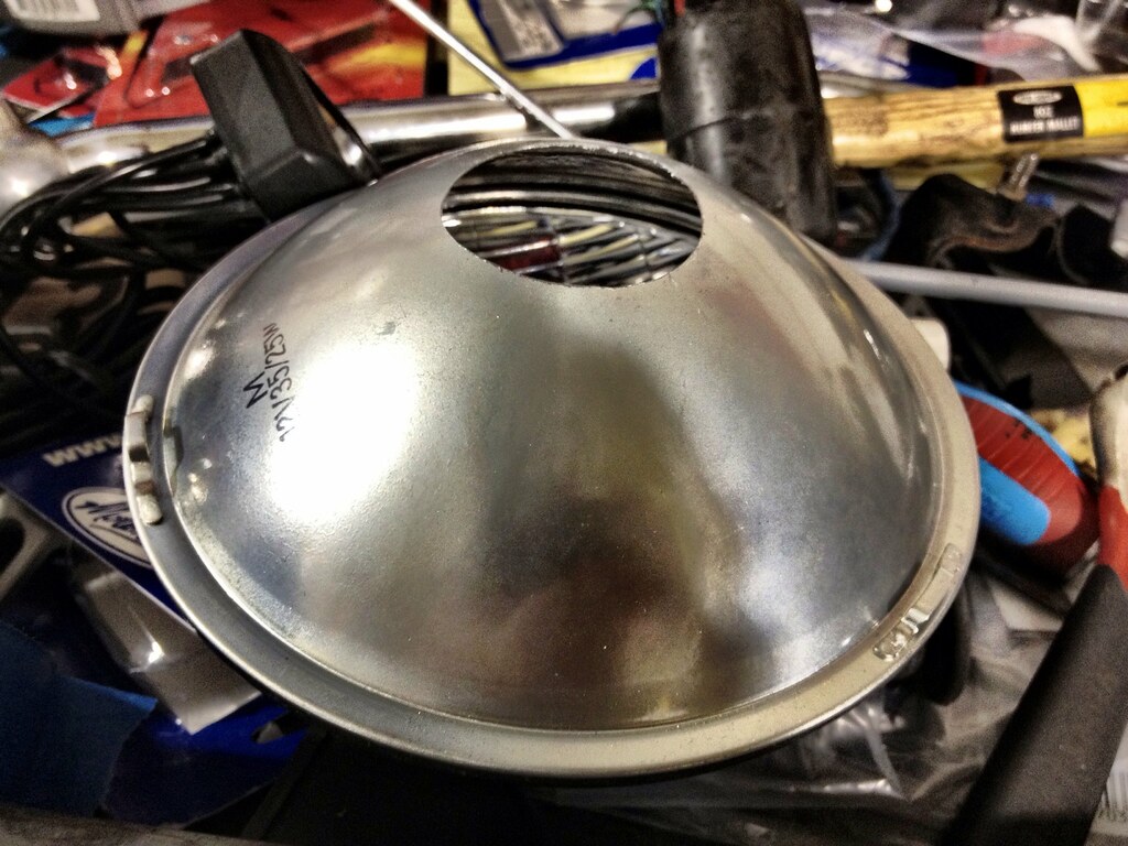
First off, take that donor headlight and cut off the plug on the back if necessary, and cut a nice clean hole in the back, at least as big as the emitter panel's diameter. I'd recommend a bit bigger simply so you have some room to err and properly extract the wires. If you're serious about making the lens work and look like the bulb and use as much of the reflector as possible, you should probably keep the hole as small as possible which mounts the LED emitter panel far back in the headlight. Once you have the hole cut, set it on a flat, level surface with the headlight lens facing toward the ceiling. Take a tape measure or ruler and make sure the outer rim is the same height all the way around, essentially checking the flatness and level of the hole. Take a dermal or file and take some material off of the high points, making sure the hole doesn't get too jagged. The smoother the cut, the more material will be effectively uses to hold on the copper heat since once mounted.
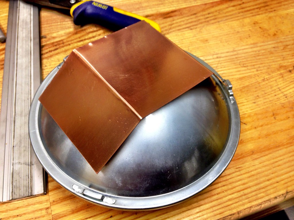
Next step I took was making the copper heat sink. I cut a 3"x6" rectangle out of the sheet I purchased with some sheet metal shears and smoothed out the cut marks best I could. They don't matter too much, I just don't looking at them. Your plate might be a different size based on the donor headlight and the hole you've made. Measure the diameter of the hole and ad about 1/2" to it, then mark it from the midpoint out on the copper plate. Draw two lines that separates the longer edges of the plate into thirds. Grab a book and head over to the vice (if you don't have a break… you know what to do if you own one), mount the copper in the jaws so that the line is parallel to the long edge and make a crease using the book to support the unclamped portion of the plate. This will make a nice tidy angle. Do the same angle again so that you create a little "C" shape-- or "S" if you want to be a weirdo. Now that you've made a little house for a mouse, set it aside, we need to work out some electrical bits.
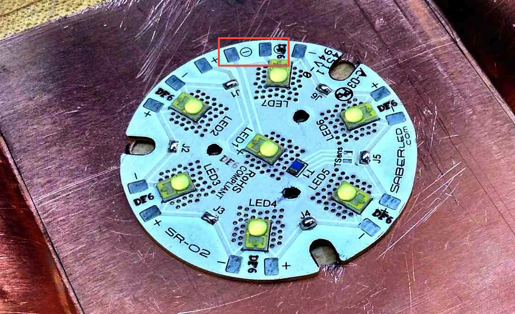
Make sure you haven't rubbed your feet on any nylon carpet or have been playing with any rubber balloons, the LED emitter panel can be static sensitive. Just make sure you've touched some grounded metal object and sit down, break out the LED emitter, and heat the soldering iron. There are little patches of exposed metal on the circuit board that say J1-6. Each of these pairs of these pads need to be bridged with solder. In my experience, this is a huge pain in the ass. Take your time, don't burn anything. If you have a good iron, set it to something like 650-700 degrees F as to not roast any of the expensive bits. Now get out a magnifying glass or turn up the light. In between Junction 6 and Junction 1 (J6, J1) you can see that there is a piece of conductive metal under the insulation on the board that shoots on it's own up to LED1. The solderable plate that it connects to (with the printed negative sign with a circle around it) is the negative terminal for the entire emitter panel now that they are all in series. You CAN NOT use any random positive/negative plate, it will not work. The correct positive terminal for the board is the one next to the previously described "circled minus" on the LED7 side, if that makes sense. There is actually a "circled plus" printed, but mine had it covered by some inspection stamp, yours might be the same. If you look close enough at the circuit board it all makes sense. Below I have noted with a red rectangle which are the correct positive and negative solder pads to use.
Once you find the right places to solder, attach a wire to each, noting which one is which. Make them a little long for now so you have room to strip and trim them later. Now that we've set up the emitter, take it to the copper plate and get it lined up as best you can right in the center with the angled ends facing up. Mark and drill the three panel mounting holes on the plate, as well as the little holes that mount the lens later. This is because the posts on the lens actually protrude past the panel and would contact the copper plate. This doesn't sound too bad, but the more gap between the emitter back and the copper plate, the less heat will be transferred. Now to drill one more hole for the wires to escape the back of the copper plate. It's best to drill this hole tangent to where the edge of the panel will be and as close to the soldered ends of the wires. Once you get all the holes drilled, take your hammer or mallet and flatten all the raised edges in the copper. Using this technique will also flatten the important part of the copper plate to better bond to your perfectly flat headlight hole… that sounds like a really awkward insult...
Now take the zinc oxide grease and do everything in your power to not get it on your clothes because it will never come out. Squeeze a little onto your finger and spread it evenly on the back of the emitter panel. You don't need a massive amount. It's sort of the consistency of toothpaste, just a thin coat will do to fill in any imperfections in the copper surface. Grab the #4 hardware and bolt it down, taking care to route the wires properly first. When you tighten it down some grease will likely squeeze out through the holes in the emitter panel. It's probably a good idea to wipe this off without getting any on the actual LEDs.
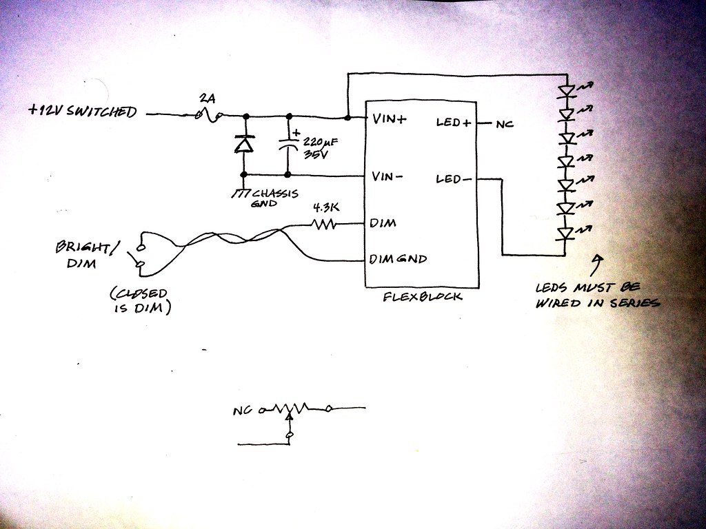
Now it's time to flip it over. To make sure we're being accurate about wire length, go ahead and epoxy the Flexblock driver to one of the outside ends of the copper plate. Try to keep in mind that at this point we're adding depth to the headlight in the place it didn't previously exist-- make sure it'll still fit in your headlight ace without contacting anything. Once the epoxy has set up enough to play with, reheat that soldering iron. Below is the wiring diagram for the LED headlight. You can forget about the resistor shown off the dimmer switch. Below it is the proper way to wire in the 10K Ohm resistor instead.
This is where things can get complicated. Writing about wiring is like trying to describe how to tie a knot. Read through it a couple times to ensure understanding. It is a long, drawn out set of notes that truthfully only takes a few minutes to complete if you're good with some solder and an iron. My dad is an electrical engineer-turned CEO of a semiconductor company. He is a wizard with electrical stuff. Much of this was designed by him and only understood by me at an elementary level, so don't feel bad to ask questions-- I'll refer them to him if I can't manage to answer them myself.
First thing to do is cut the LED+ wire (white or light gray) to about an inch long. Do not strip it. Get creative and insulate the business end of it. We simply put some heat shrink over it and let it overhang before heating it. Now take the capacitor and diode. Fit the diode in between the capacitor's leads (the capacitor should sit coaxial to the diode, if you've bought a diode with leads shooting out both ends, bend them 90 degrees) and wrap the positive lead around the capacitor's and solder it in place. Do the same for the negative leads. Now take the little bundle and epoxy it directly above the VIN+ and VIN- wires on the Flexblock with the leads from the capacitor facing the wires. I did this step after I had attached the capacitor/diode to the wires and it didn't epoxy well. The reason we attach them to the Flexblock is to keep them from vibrating too much. Maybe an overkill step, but it also keeps the wires from fatiguing. Take the VIN+ wire and cut it long short enough to just reach the bottom of the capacitor's positive lead. Grab your favorite [wire] stripper and take off about 1/4" of the insulation from the end. Twist all the small wires to make them stay together and wrap it around the bottom of the positive lead, leaving maybe a 1/4" of lead below. Now grab some wire, maybe 6-7" long, red if you have it. Take one end and, once again, take 1/4" of the insulation off. Wrap it just below the VIN+ wire on the capacitor positive lead, making sure the wire is heading away from the capacitor itself. Do your best to keep both wires pointing in the right direction and wound around the lead and hit them with some solder. Now take another bit of wire, again, red is preferred, and make sure it'll reach the positive wire from the emitter panel after it has gone through the copper plate. Strip off some insulation from both ends and wrap one around the point where the diode wraps the positive lead on the capacitor and solder. Make sure that when you reheat the solder holding the diode in place it doesn't move much-- best to keep things tidy for possible troubleshooting should something go wrong. Below is a photo of how I did my capacitor/diode bundle. Sorry it's not a better picture!
The negative side is much easier. Just grab some wire, black is preferred, strip the end, and wrap and solder it to the negative lead of the capacitor. Now that you have that whole bundle connected just slip some heat shrink (or tape if you're a Neanderthal) over it as far up as you can and hit it with the heat gun. Take that open end of the wire heading to the positive emitter panel and connect it with our new wire from the positive side of the capacitor/diode. If you're using heat shrink make sure you slip it over one end first, don't be a dummy like me. Fill both wire ends with some solder, touch them together, and reheat. Once cooled, slip the heat shrink over the connection to insulate any exposed metal, and heat it with the gun. The negative wire for the emitter panel will use the same process to join it to the LED- wire on the Flexblock. The wire heading from the negative end of the capacitor will be joined up with 12V-, however you'd like to achieve that. Chassis ground should work fine. The associated positive wire should join up to the 2A fuse. I simply mounted the fuse holder with a wire clip on the other side of the copper plate, ran the wires together, and put a Honda bullet connector on it to connect with the old headlight switched 12V+.
Now for the dimmer switch. There are gray and purple wires coming from the Flexblock marked DIM+ and DIM- respectively. It doesn't matter which is which. All you do is connect them and the light will go out completely. Any resistance in this circuit will dim the light proportionally. The use of a trim potentiometer allows us to dial in our ideal amount of light when the circuit is connected. Without knowing how every application's high/low beam switch is wired, I'll just explain to the point where my wires are terminated with a Honda bullet connector. My CB77 has both a high and low beam wire heading from the switch, so it was easy to work with. When the switch closes the circuit it activates the dimmer.
Take your 3-wire, 10K Ohm trim pot and epoxy it where you'd like it on the copper plate or on the Flexblock itself. Once solidly placed, take your DIM+ or DIM- wires, cut it to length, take 1/4" of insulation off the end, wind the filament wires to make them easier to work with, slip some heat shrink over the end and pull it out of the way, and connect it to the middle lead on the pot. If your trim pot has little holes cut into the leads you can push the wires through and bend them around to aid in soldering. Now take a short length of extra wire. Cut off the insulation from both ends, soldering one end to either of the outside leads on the pot. Slip some heat shrink over the end and push it plus the piece you placed on the middle pole all the way up to the base of the trim pot. Grab the other end of the open wire and put whatever connector you want on it. Do the same to whichever DIM wire you didn't attach to the pot. These two wires need to be connected with your high/low switch to activate low beam. At this point I'd also spread a little more epoxy over the end of the wires protruding from the trim pot-- just make sure your epoxy isn't electrically conductive. The leads are very small and very weak, a little tugging could pull the solder joints off, or worse, pull the leads out of the pot completely.
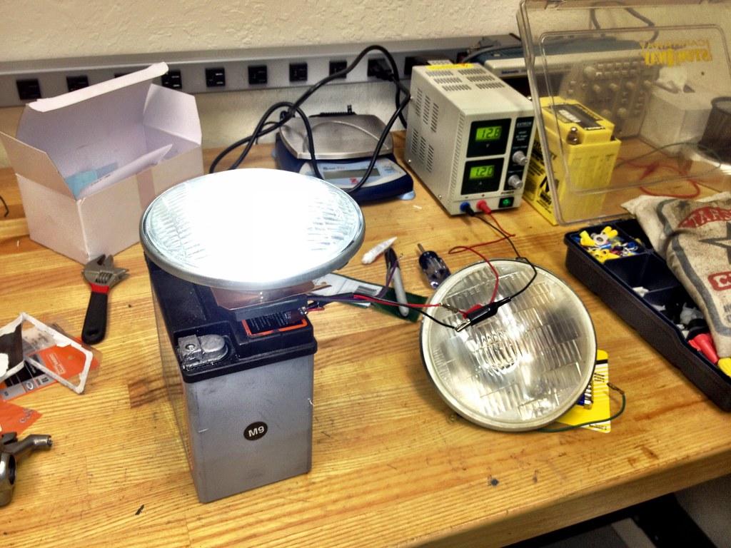
Now's a good time to test the light before you actually mount it to the headlight itself. Just connect the fused positive wire and the negative wire from the capacitor/diode bundle to a bike/car battery. If all went right in assembly it'll light up VERY bright. Seriously, don't look right at it, you'll definitely loose some brain cells. Once lit, touch the two ends of the dimmer switch wires together and the light should dim a little. You can adjust it with the sweeper on the trim pot. If it all works, you're ready to turn it into an official headlight. This is obviously a pretty self-explanatory step involving gratuitous amounts of epoxy and some patience. It seems my headlight didn't mount so well the first time and I'll end up using a lot more epoxy to seal the gaps. Roughing up the copper plate and/or the hole in the headlight might give some extra surface area for the epoxy to hold to.
So there you go, and LED headlight that will use 15W on high beam and as little wattage on low beam as you like, won't waste heat, and will end up being significantly safer. Please post in here and say what you think. If you've made the light, tell all what you've changed or would like to change. There's an evolution to every project and every design, we've just learned to stand up.
Here are a few extra pictures for your reference. I apologize for not taking more photos along the way. I was way too excited to get it lit than to stop and document anything! Below are also some videos of the light post-completion. I'll likely post more once I get the bike running so we can all see how it works out on the open road.

http://www.youtube.com/watch?v=PYulBN6itio
http://www.youtube.com/watch?v=VlrxBZ3165A
http://www.youtube.com/watch?v=hjUHdeP7XbI
http://www.youtube.com/watch?v=kiaZU2QWm5Y
Anyway, I started out with a problem: The CB77 doesn't charge the battery with the headlight on. This is already an issue for a standard bike, especially when law states the bike must have the headlight lit at all times to ride it on the street. My application required even more electricity from the charging system, all while appealing to that previously stated law. My bike was to be electronically fuel injected (build is elsewhere on this forum) so the fuel pump and ECU would require a lot of juice. My stock headlight used up about 25W on low beam and 35W on high beam. Even the taillight used up 10W on it's own! As you will see later and as you build your own LED headlight, incandescent bulbs are extremely inefficient.
At the time of writing this I have completed the build stage for the most part, have done bench testing, but no riding. I do not yet know how it will stand up to vibration or dramatic heat change. That said, the bench tests have netted some impressive results. If there are unforeseen issues in the previously mentioned areas, I'm sure it won't be too difficult to modify the assembly to fix any problems. Here are the features of my current setup:
-Looks reasonably like the original headlight
-Uses a maximum of 15W on high beam
-Infinitely adjustable low beam setting, I'm currently using 3W
-Very low heat
-Shines bright white, not yellow
-Light is very intense even on low beam to be seen better.
-Glass still says DOT, a dumb piggy might not know the difference
A quick note on LEDs. They are very efficient nowadays but still create a pretty good amount of heat. On the mounting plate directly behind the LED panel I see about 136 degrees Fahrenheit. This isn't going to cause some nuclear meltdown, but it should be reason to think about getting rid of some of it and making sure that the emitter panel and the required heat sink doesn't get close to anything that can melt. LEDs are not like incandescent bulbs. They cannot just be hooked up to a bike's battery voltage. The high current will cook them. You need a voltage driver to regulate the power supply. LEDs are also very intense but still produce light in roughly 180 degree patterns. They need a lens to focus the light in your desired pattern.
So here's what you need to make the light I created:
-Donor headlight. I bought a cheap knockoff sealed beam unit.
-LED emitter panel. I purchased this one: http://www.luxeonstar.com/Cool-White-5650K-7-LED-40mm-Round-Assembly-p/sr-02-wc310.htm This emitter panel is rated up to 1000mA but I feel it probably creates an inordinate amount of heat at that output.
-DC voltage driver. This one is dimmable for a low beam setting: http://www.luxeonstar.com/700mA-Externally-Dimmable-FlexBlock-Driver-p/a011-d-v-700.htm If you're daring enough to get the emitters up to 1000mA you'll have to purchase the next model up.
-Focusing lens. This one is 50 degree spread: http://www.luxeonstar.com/Polymer-Optics-7-LED-Cluster-50-Optic-p/262.htm This lens puts out a lot of light to the sides and even uses the headlight reflector to send some light in a somewhat natural direction. The same company also sells a 15 degree lens that probably acts more like a car's high beam and will work even more effectively, of course at a sacrifice of some side light.
-Copper sheet. Something bendable works quite well but it needs to support the emitter panel and be able to mount to the headlight reflector.
-Diode. This is half of an anti-reverse polarity protection. It's a 3A 50V rectifier diode and can be found at any electronics store like Radio Shack or here at Digi-Key: http://search.digikey.com/us/en/products/1N5400-TP/1N5400-TPTR-ND/950387
-Capacitor. The other half of the anti-reverse polarity protection. The one I used is a 220µF 35V model found here: http://search.digikey.com/us/en/products/EKZE350ELL221MJC5S/565-1690-ND/756206
-10K Ohm trim potentiometer. This allows you to tune the resistance and therefore the amount of dimming on low beam mode. These can be purchased at any electronics store like Radio Shack. Try to find one that can be mounted with the trim adjuster facing opposite of the best mounting surface.
-2A fuse and fuse holder.
-Steel epoxy. Doesn't matter what kind. JB Weld is good but it takes a lot of time to set up. I used some quick set stuff that worked reasonably well in larger quantities. Make sure whatever you use has a decent heat rating, something above 200F would be useful.
-#4 philips head bolts, washers, and nuts.
-Zinc-oxide grease. This is heat conductive grease that will spread the head from the back of the emitter panel to the copper heat sink.
-Wire, since they haven't developed wireless wires yet. 18G usually works pretty well. Doesn't matter, everything is under 2A.
-Solder and iron. You might also want to insulate things with some heat shrink. Please, if you can, use a good soldering iron, preferably one that you can pick the temperature on. They're not that expensive anymore and it will be worth it not too cook any of the delicate parts we're working with.
-Solder wick. Ask Radio Shack for a small spool of it. Soldering the LED emitter panel can be a bit of a pain, you don't want to use too much solder and bridge the wrong places. Wicks are easy to use to sop up some extra metal after using the iron.
-Heat gun. For the heat shrink if you choose to use it-- I recommend you do. Electrical tape sucks.
-Metal brake. A vice and a hardback book usually work as well. Try not to use a bible, good to keep the Big Guy on our side when dealing with electricity.
-Screwdriver and crescent wrench. Try to find some clean ones.
-Rubber mallet or small ballpein hammer. For when things go bad.
-Needle nose pliers or forceps. These are good to have while dealing with tiny electronics.
-Wire stripper and crimper.
The process:
First off, take that donor headlight and cut off the plug on the back if necessary, and cut a nice clean hole in the back, at least as big as the emitter panel's diameter. I'd recommend a bit bigger simply so you have some room to err and properly extract the wires. If you're serious about making the lens work and look like the bulb and use as much of the reflector as possible, you should probably keep the hole as small as possible which mounts the LED emitter panel far back in the headlight. Once you have the hole cut, set it on a flat, level surface with the headlight lens facing toward the ceiling. Take a tape measure or ruler and make sure the outer rim is the same height all the way around, essentially checking the flatness and level of the hole. Take a dermal or file and take some material off of the high points, making sure the hole doesn't get too jagged. The smoother the cut, the more material will be effectively uses to hold on the copper heat since once mounted.
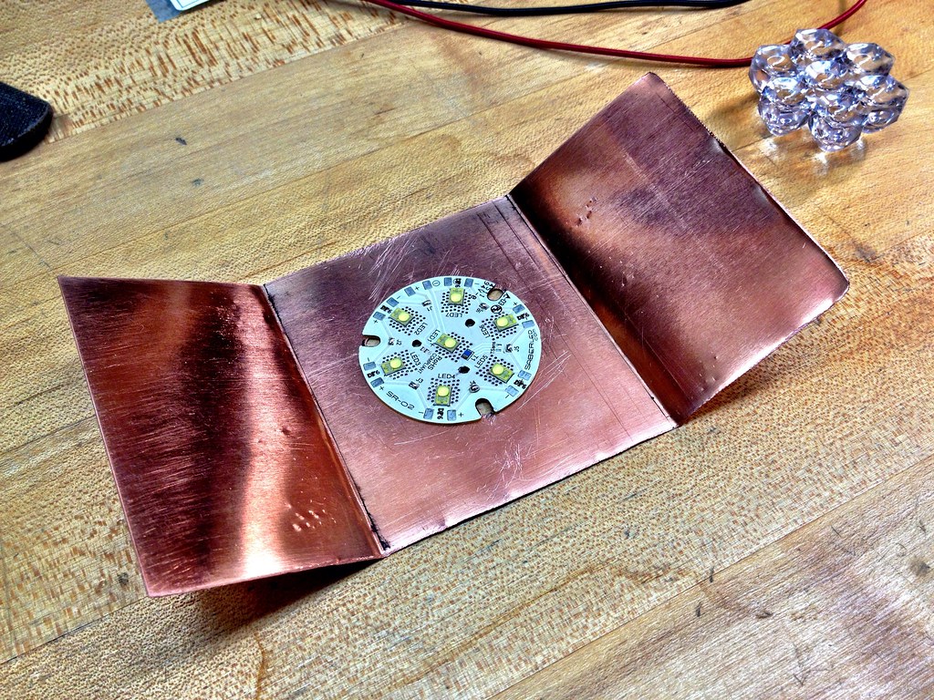
Next step I took was making the copper heat sink. I cut a 3"x6" rectangle out of the sheet I purchased with some sheet metal shears and smoothed out the cut marks best I could. They don't matter too much, I just don't looking at them. Your plate might be a different size based on the donor headlight and the hole you've made. Measure the diameter of the hole and ad about 1/2" to it, then mark it from the midpoint out on the copper plate. Draw two lines that separates the longer edges of the plate into thirds. Grab a book and head over to the vice (if you don't have a break… you know what to do if you own one), mount the copper in the jaws so that the line is parallel to the long edge and make a crease using the book to support the unclamped portion of the plate. This will make a nice tidy angle. Do the same angle again so that you create a little "C" shape-- or "S" if you want to be a weirdo. Now that you've made a little house for a mouse, set it aside, we need to work out some electrical bits.
Make sure you haven't rubbed your feet on any nylon carpet or have been playing with any rubber balloons, the LED emitter panel can be static sensitive. Just make sure you've touched some grounded metal object and sit down, break out the LED emitter, and heat the soldering iron. There are little patches of exposed metal on the circuit board that say J1-6. Each of these pairs of these pads need to be bridged with solder. In my experience, this is a huge pain in the ass. Take your time, don't burn anything. If you have a good iron, set it to something like 650-700 degrees F as to not roast any of the expensive bits. Now get out a magnifying glass or turn up the light. In between Junction 6 and Junction 1 (J6, J1) you can see that there is a piece of conductive metal under the insulation on the board that shoots on it's own up to LED1. The solderable plate that it connects to (with the printed negative sign with a circle around it) is the negative terminal for the entire emitter panel now that they are all in series. You CAN NOT use any random positive/negative plate, it will not work. The correct positive terminal for the board is the one next to the previously described "circled minus" on the LED7 side, if that makes sense. There is actually a "circled plus" printed, but mine had it covered by some inspection stamp, yours might be the same. If you look close enough at the circuit board it all makes sense. Below I have noted with a red rectangle which are the correct positive and negative solder pads to use.
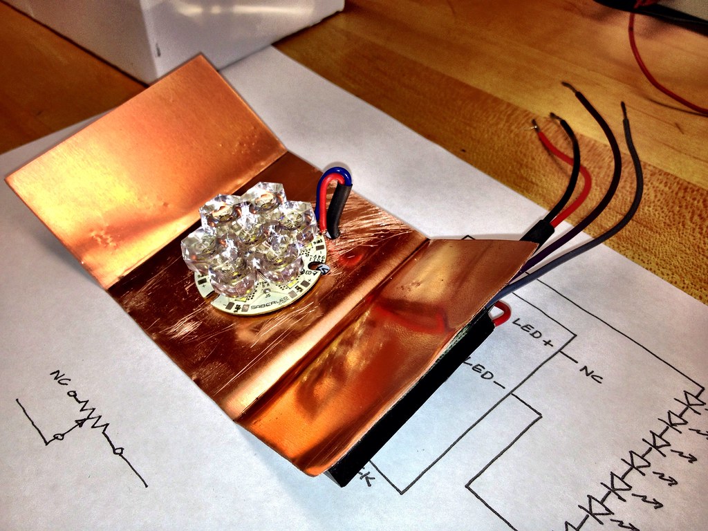
Once you find the right places to solder, attach a wire to each, noting which one is which. Make them a little long for now so you have room to strip and trim them later. Now that we've set up the emitter, take it to the copper plate and get it lined up as best you can right in the center with the angled ends facing up. Mark and drill the three panel mounting holes on the plate, as well as the little holes that mount the lens later. This is because the posts on the lens actually protrude past the panel and would contact the copper plate. This doesn't sound too bad, but the more gap between the emitter back and the copper plate, the less heat will be transferred. Now to drill one more hole for the wires to escape the back of the copper plate. It's best to drill this hole tangent to where the edge of the panel will be and as close to the soldered ends of the wires. Once you get all the holes drilled, take your hammer or mallet and flatten all the raised edges in the copper. Using this technique will also flatten the important part of the copper plate to better bond to your perfectly flat headlight hole… that sounds like a really awkward insult...
Now take the zinc oxide grease and do everything in your power to not get it on your clothes because it will never come out. Squeeze a little onto your finger and spread it evenly on the back of the emitter panel. You don't need a massive amount. It's sort of the consistency of toothpaste, just a thin coat will do to fill in any imperfections in the copper surface. Grab the #4 hardware and bolt it down, taking care to route the wires properly first. When you tighten it down some grease will likely squeeze out through the holes in the emitter panel. It's probably a good idea to wipe this off without getting any on the actual LEDs.
Now it's time to flip it over. To make sure we're being accurate about wire length, go ahead and epoxy the Flexblock driver to one of the outside ends of the copper plate. Try to keep in mind that at this point we're adding depth to the headlight in the place it didn't previously exist-- make sure it'll still fit in your headlight ace without contacting anything. Once the epoxy has set up enough to play with, reheat that soldering iron. Below is the wiring diagram for the LED headlight. You can forget about the resistor shown off the dimmer switch. Below it is the proper way to wire in the 10K Ohm resistor instead.
This is where things can get complicated. Writing about wiring is like trying to describe how to tie a knot. Read through it a couple times to ensure understanding. It is a long, drawn out set of notes that truthfully only takes a few minutes to complete if you're good with some solder and an iron. My dad is an electrical engineer-turned CEO of a semiconductor company. He is a wizard with electrical stuff. Much of this was designed by him and only understood by me at an elementary level, so don't feel bad to ask questions-- I'll refer them to him if I can't manage to answer them myself.
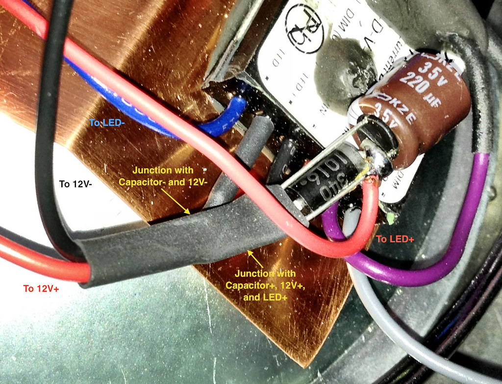
First thing to do is cut the LED+ wire (white or light gray) to about an inch long. Do not strip it. Get creative and insulate the business end of it. We simply put some heat shrink over it and let it overhang before heating it. Now take the capacitor and diode. Fit the diode in between the capacitor's leads (the capacitor should sit coaxial to the diode, if you've bought a diode with leads shooting out both ends, bend them 90 degrees) and wrap the positive lead around the capacitor's and solder it in place. Do the same for the negative leads. Now take the little bundle and epoxy it directly above the VIN+ and VIN- wires on the Flexblock with the leads from the capacitor facing the wires. I did this step after I had attached the capacitor/diode to the wires and it didn't epoxy well. The reason we attach them to the Flexblock is to keep them from vibrating too much. Maybe an overkill step, but it also keeps the wires from fatiguing. Take the VIN+ wire and cut it long short enough to just reach the bottom of the capacitor's positive lead. Grab your favorite [wire] stripper and take off about 1/4" of the insulation from the end. Twist all the small wires to make them stay together and wrap it around the bottom of the positive lead, leaving maybe a 1/4" of lead below. Now grab some wire, maybe 6-7" long, red if you have it. Take one end and, once again, take 1/4" of the insulation off. Wrap it just below the VIN+ wire on the capacitor positive lead, making sure the wire is heading away from the capacitor itself. Do your best to keep both wires pointing in the right direction and wound around the lead and hit them with some solder. Now take another bit of wire, again, red is preferred, and make sure it'll reach the positive wire from the emitter panel after it has gone through the copper plate. Strip off some insulation from both ends and wrap one around the point where the diode wraps the positive lead on the capacitor and solder. Make sure that when you reheat the solder holding the diode in place it doesn't move much-- best to keep things tidy for possible troubleshooting should something go wrong. Below is a photo of how I did my capacitor/diode bundle. Sorry it's not a better picture!
The negative side is much easier. Just grab some wire, black is preferred, strip the end, and wrap and solder it to the negative lead of the capacitor. Now that you have that whole bundle connected just slip some heat shrink (or tape if you're a Neanderthal) over it as far up as you can and hit it with the heat gun. Take that open end of the wire heading to the positive emitter panel and connect it with our new wire from the positive side of the capacitor/diode. If you're using heat shrink make sure you slip it over one end first, don't be a dummy like me. Fill both wire ends with some solder, touch them together, and reheat. Once cooled, slip the heat shrink over the connection to insulate any exposed metal, and heat it with the gun. The negative wire for the emitter panel will use the same process to join it to the LED- wire on the Flexblock. The wire heading from the negative end of the capacitor will be joined up with 12V-, however you'd like to achieve that. Chassis ground should work fine. The associated positive wire should join up to the 2A fuse. I simply mounted the fuse holder with a wire clip on the other side of the copper plate, ran the wires together, and put a Honda bullet connector on it to connect with the old headlight switched 12V+.
Now for the dimmer switch. There are gray and purple wires coming from the Flexblock marked DIM+ and DIM- respectively. It doesn't matter which is which. All you do is connect them and the light will go out completely. Any resistance in this circuit will dim the light proportionally. The use of a trim potentiometer allows us to dial in our ideal amount of light when the circuit is connected. Without knowing how every application's high/low beam switch is wired, I'll just explain to the point where my wires are terminated with a Honda bullet connector. My CB77 has both a high and low beam wire heading from the switch, so it was easy to work with. When the switch closes the circuit it activates the dimmer.
Take your 3-wire, 10K Ohm trim pot and epoxy it where you'd like it on the copper plate or on the Flexblock itself. Once solidly placed, take your DIM+ or DIM- wires, cut it to length, take 1/4" of insulation off the end, wind the filament wires to make them easier to work with, slip some heat shrink over the end and pull it out of the way, and connect it to the middle lead on the pot. If your trim pot has little holes cut into the leads you can push the wires through and bend them around to aid in soldering. Now take a short length of extra wire. Cut off the insulation from both ends, soldering one end to either of the outside leads on the pot. Slip some heat shrink over the end and push it plus the piece you placed on the middle pole all the way up to the base of the trim pot. Grab the other end of the open wire and put whatever connector you want on it. Do the same to whichever DIM wire you didn't attach to the pot. These two wires need to be connected with your high/low switch to activate low beam. At this point I'd also spread a little more epoxy over the end of the wires protruding from the trim pot-- just make sure your epoxy isn't electrically conductive. The leads are very small and very weak, a little tugging could pull the solder joints off, or worse, pull the leads out of the pot completely.
Now's a good time to test the light before you actually mount it to the headlight itself. Just connect the fused positive wire and the negative wire from the capacitor/diode bundle to a bike/car battery. If all went right in assembly it'll light up VERY bright. Seriously, don't look right at it, you'll definitely loose some brain cells. Once lit, touch the two ends of the dimmer switch wires together and the light should dim a little. You can adjust it with the sweeper on the trim pot. If it all works, you're ready to turn it into an official headlight. This is obviously a pretty self-explanatory step involving gratuitous amounts of epoxy and some patience. It seems my headlight didn't mount so well the first time and I'll end up using a lot more epoxy to seal the gaps. Roughing up the copper plate and/or the hole in the headlight might give some extra surface area for the epoxy to hold to.
So there you go, and LED headlight that will use 15W on high beam and as little wattage on low beam as you like, won't waste heat, and will end up being significantly safer. Please post in here and say what you think. If you've made the light, tell all what you've changed or would like to change. There's an evolution to every project and every design, we've just learned to stand up.
Here are a few extra pictures for your reference. I apologize for not taking more photos along the way. I was way too excited to get it lit than to stop and document anything! Below are also some videos of the light post-completion. I'll likely post more once I get the bike running so we can all see how it works out on the open road.
http://www.youtube.com/watch?v=PYulBN6itio
http://www.youtube.com/watch?v=VlrxBZ3165A
http://www.youtube.com/watch?v=hjUHdeP7XbI
http://www.youtube.com/watch?v=kiaZU2QWm5Y


