We noticed you are blocking ads. DO THE TON only works with community supporters. Most are active members of the site with small businesses. Please consider disabling your ad blocking tool and checking out the businesses that help keep our site up and free.
You are using an out of date browser. It may not display this or other websites correctly.
You should upgrade or use an alternative browser.
You should upgrade or use an alternative browser.
Project CB690 (KTM 690 engine in a CB550f frame)
- Thread starter goodoltup
- Start date
goodoltup
Been Around the Block
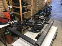
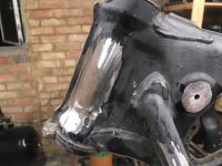
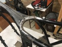
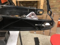
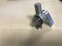
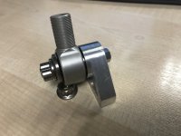
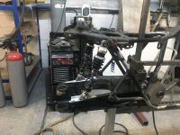
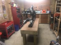
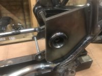
Off the frame jig now, as the swingarm pivots and plates are tacked in, the jig now is not needed. I will use it for convenience only from here on out. I wanted to get the frame off the jig in order to final measure up the steering head and bearings, so the stem can be drawn and ordered. Took this opportunity to do some more frame work. The steering lock was removed and the hole welded up.
Attachments
goodoltup
Been Around the Block
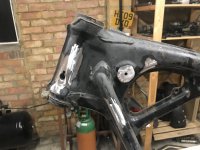
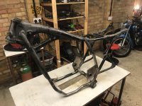
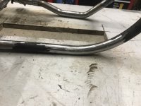
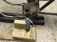
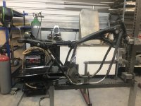
Also removed the cb550 front right motor mount. It came off pretty easily actually, as it was only welded on two sides. My Bosch angle grinder got quite a workout, though. Also removed the cb550 rear fuel tank mount / frame brace. This was interfering with the K&N air filter that I bought for the bike, so I cut it out and will replace it with a custom part later.
Attachments
goodoltup
Been Around the Block
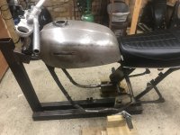
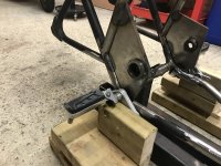
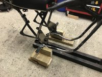
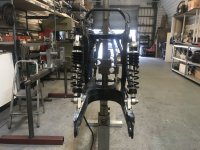
Quickly made a jig to mock up the footpeg locations. I put the bars, tank, and seat on, and had a sit on the bike. I found actually that the footrest location felt pretty good close to where they were located on the cb550 originally, maybe just a touch to the rear. The footpegs are Honda cb250 or something, the mounts are gsx650f. The aluminium brackets shown will not be used, only the pivot bracket.
Attachments
goodoltup
Been Around the Block
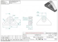
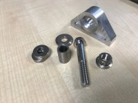
Late last year I drew up the lower shock mount as shown in the above post. It was quoted by three rapid prototyping machinist companies, and finally produced by a company called Shift.BZ. The cost was around 200 EUR for two, delivery time was less than 5 weeks. As an engineer I typically get 8 weeks for machined parts for our business, so 5 is great. Highly recommended.
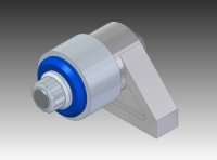
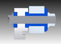
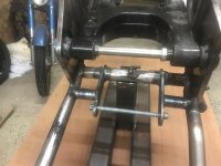
Below is a CAD model of the shock mount with the bolts and washers installed. I decided on using a through-bolt instead of a clevis type, because of the distance needed between the shocks would have required quite a weird looking lower mount. The lower mount as machined will be welded onto the existing KTM swingarm. I cut all the parts shown in blue out of titanium on the lathe.
Below is a CAD model of the shock mount with the bolts and washers installed. I decided on using a through-bolt instead of a clevis type, because of the distance needed between the shocks would have required quite a weird looking lower mount. The lower mount as machined will be welded onto the existing KTM swingarm. I cut all the parts shown in blue out of titanium on the lathe.
Attachments
goodoltup
Been Around the Block
Hi,
I have no problems with the Hitbox at all. Other than the fact that the first one that I bought was dead right out of the box, it's replacement has been perfectly suitable. I'm a beginner TIG user and don't put that much use on it, so perhaps with heavy use it might struggle, but I don't know. Build quality is acceptable, and no bits or pieces have broken yet. The MMA welding function works fine as well. I'm not totally sure that the tig cups are interchangeable with major brands, that remains to be seen. I'm honestly struggling to say anything bad about it.
I have no problems with the Hitbox at all. Other than the fact that the first one that I bought was dead right out of the box, it's replacement has been perfectly suitable. I'm a beginner TIG user and don't put that much use on it, so perhaps with heavy use it might struggle, but I don't know. Build quality is acceptable, and no bits or pieces have broken yet. The MMA welding function works fine as well. I'm not totally sure that the tig cups are interchangeable with major brands, that remains to be seen. I'm honestly struggling to say anything bad about it.
goodoltup
Been Around the Block
CB360j, I completely agree, the machinists I use for my job would normally charge about £800 for ANYTHING, just to get the machine setup. This company Shift.BZ is network of machinists that bid on jobs when they have spare capacity, so the prices can be lower. The parts don't come with an inspection report or materials certificate, as I would normally expect, but the parts were of very high quality and measured up fine.
Pete12
Been Around the Block
goodoltup said:Pete12, I REALLY enjoyed your thread on the CB450, I will give it a good read through and see if there are some things that you did that I may try on my machine. Cheers!
Thanks goodoltup, but you are doing a great job on your bike, I doubt you'll need anything from me.
I love seeing such an ambitious idea come to life. Nice work man. I'll definitely be following along
goodoltup
Been Around the Block
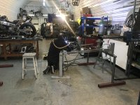
Lots of progress has been made, but few updates. Big day! I brought the frame to be welded professionally by a frame builder. He put it on his jig and found that it was tacked up pretty square, which pleased me. All bits that I tacked were welded up properly, including the frame side plates, swingarm pivots, lower engine mounts, top shock mounts, etc. The aluminium lower shock mounts were also welded.
Attachments
goodoltup
Been Around the Block
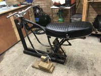
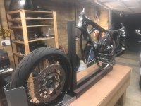
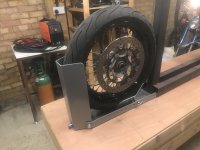
I quickly made a better work table out of some scrap. It took about an hour to build, and it's pretty stout. I will likely disassemble and dispose of it after the build, so I didn't spend a ton of effort on it. But it did come out pretty nice. I got a wheel chock so when the time comes to take it off the jig (it's back on the jig temporarily after welding just to hold it) I will have a way to secure it. I will probably put it on the centre stand with the wheel chock during the rest of the build.
Attachments
goodoltup
Been Around the Block
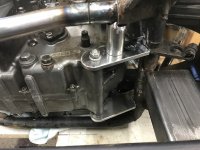
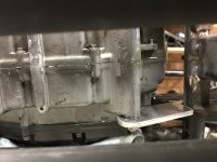
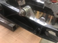
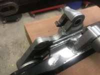
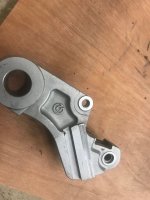
There was some interference with the brake torque arm, so I milled off the ledge on the arm with the Haas at work. It's tough to explain, I should have taken some before pictures. There was a ledge, or overhang, on the torque arm who's purpose appeared to be to keep the arm attached to the swingarm during wheel installation. With it gone it might be more fiddly to get the wheel on, but I don't think that's a huge problem.
Attachments
goodoltup
Been Around the Block
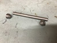
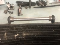
Made some radiator supports on the Colchester. These bits will be welded together, and the tube will be welded to the frame when it's time to mock up the radiator. May not use these for a while, just had some extra time on the lathe after work.