1970 Triumph Tiger 650

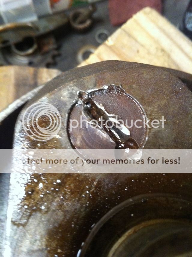
Finally got the sludge trap plug out. This was an SOB to get out. It took 10 minutes with the BFH and the impact to turn it 360°. Another 5 or so to get the next 360° and then I put the 1/2" air impact to get it the rest of the way. Plug is pretty beat up from previous work. I'm surprised this bike had so much work done before my brother bought it 2 years old in 72. The plug looks as though the "stake" was drilled out with a too large bit, but in the plug, that is being replaced, and not the wheels. I don't know why this plug needs to be staked when it is so freaking tight going in it needs serious impact tools to remove. The replacement plug is an allen and not a slot.
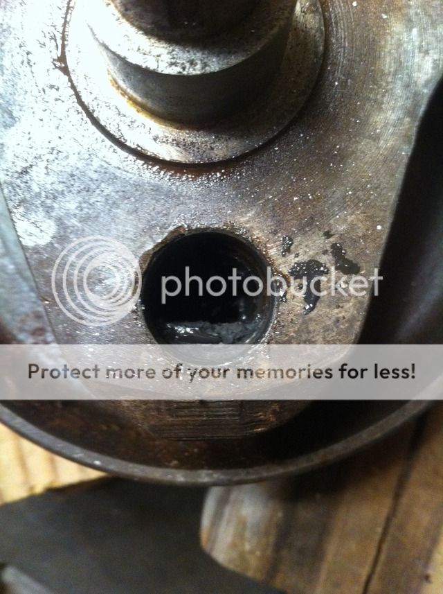
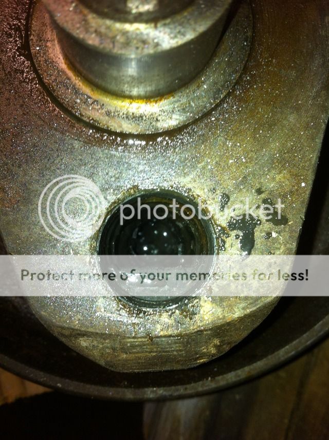


Yep, it needs cleaning. You got lucky....at least it came out. :) I've had to resort to a drill on a great many of them. I have found that a large easy-out works great for removing the internal tube...
once the locator bolt is removed, give the easy-out a light tap in, a light twist and out it comes.
 
goldy said:
Yep, it needs cleaning. You got lucky....at least it came out. :) I've had to resort to a drill on a great many of them. I have found that a large easy-out works great for removing the internal tube...
once the locator bolt is removed, give the easy-out a light tap in, a light twist and out it comes.
I'll see if I have an easy break off that size. The recommended tool is a 12mm tap to do the same as the easy out.
I was thinking I was going to have to drill 2 holes in the plug and insert rods I could put an adjustable wrench on t turn it out. Watching "Lunmad's" videos on youtube showed it took him as long as me to get it out. It seems like and interference fit all the way out. I see the allen plug being a huge improvement over this design, though some say the allen plugs fit looser and realize they need to be tightly sealed or you would lose oil pressure which is a bad thing. :(
 
Was able to remove the plug and strip the cases completely. Had them cleaned today and jumped right on to powder coating them in a Raven Texture Black. They came out perfect.


Sludge plug arrived today from across the pond and got it installed. Waiting on a main bearing and HondaBond to show up , hopefully tomorrow, to begin the reassembly.


The allen plug is much easier to deal with than the stock slotted plug that is very tight to get in and out.
I find staking and LocTiteing this plug to be totally redundant. It took a 2lb sledge and an impact and 10 minutes to turn it out one revolution. There's no beating the positive action of an allen.

 
Have most of the bottom end back together. Slow and methodical as I only want to do it once. I already had a brain fart after taking the crank to be polished. long story short the machinist pulled off a main bearing to polish the crank and then reinstalled it on the wrong side. I got home and dropped the crank in it's main bearing race and glued the case halves back together and called it a day. When I started fresh the next day and started to try and assemble the next bits nothing seemed to be right. That's when I noticed I had the crank in backwards and had to split the cases and start over, fun.


Slikwilli over on the SOHC4 forum is about finished with my rear rotor carrier. Should have it back early this week and then all I need is to make a brace bar and slotted tab for the swing arm to tie up the rear modifications.
Minimal in design and done that way for function and as small as needed. I'll probably polish it to match the front chrome rotors carriers.

 
o1marc said:
Slikwilli over on the SOHC4 forum is about finished with my rear rotor carrier.
Slikwilli is here too, just in case it matters. Those rotors look wonderful.
 
deviant said:
Slikwilli is here too, just in case it matters. Those rotors look wonderful.
Ya, I forgot he was here also. He made the carrier, the rotor is a stock 09 Triumph 675 unit for the rear, both pics are of the same set.
 
o1marc said:
Slikwilli over on the SOHC4 forum is about finished with my rear rotor carrier. Should have it back early this week and then all I need is to make a brace bar and slotted tab for the swing arm to tie up the rear modifications.
Minimal in design and done that way for function and as small as needed. I'll probably polish it to match the front chrome rotors carriers.

thats nice,very nice slick is a real crazftsman
this triumph will you get to ride it soon ? i see you got some string attached, so you dont loose track of the timinm g chain suks fishing one out the crankcase
 
xb33bsa said:
thats nice,very nice slick is a real crazftsman
this triumph will you get to ride it soon ? i see you got some string attached, so you dont loose track of the timinm g chain suks fishing one out the crankcase

Huh, what string are you talking about? There is no chain in the crankcase of a Triumph, nor is there a timing chain on a Triumph. Sure you're looking at the right thread? ???
 
o1marc said:
Huh, what string are you talking about? There is no chain in the crankcase of a Triumph, nor is there a timing chain on a Triumph. Sure you're looking at the right thread? ???
Pushrod power all the way baby!
 
Never seen black cases on a 70's Triumph, gonna look good! What's the plan for the cylinders and heads?
 
johnu said:
Never seen black cases on a 70's Triumph, gonna look good! What's the plan for the cylinders and heads?
Actually my brother had painted the cases black way back in the early 70's. Cylinders are already black. I'm thinking of doing the head black also and then sanding the fin edges. The stock edges are kinda sharp and not flat so I'm not sure how much sanding will be needed to make it look right.


The cases are a texture black while the covers are all Matte Black.
 
o1marc said:
Huh, what string are you talking about? There is no chain in the crankcase of a Triumph, nor is there a timing chain on a Triumph. Sure you're looking at the right thread? ???
i was pullin yer leg ,just dry humpin' ;D
 
xb33bsa said:
i was pullin yer leg ,just dry humpin' ;D
I figured out what you were referring to. Was waiting your reply to answer. What you probably see is the only thing I don't like about HondaBond, it's too gray and sticks out like a sore thumb on my black motor. I have to go over all the spots with a Black Sharpie paint pen to hide them.
You left no smiley or anything so I didn't know if you were pissing on my leg and telling me it's raining, or if you were just drunk. ;D
 
A little more progress. Got the custom made rotor carrier back, thanks to Slikwilli for knocking that out for me.


I don't like the routing of the brake line with the 90° fitting on the caliper, so I might have the custom brake line made with another 90° fitting to lessen the exposure of the brake line.


The space between the caliper bracket and the caliper itself on the caliper bolt will be filled with a Heim joint for the brake stay rod.
 
is the torque arm/rod going to be up top under compression ?
ideally its down below where it is under tension load ,it can be a lighter simpler deal to design and fab as well
i assume the caliper is up high because you want it there, no argument about that,however you still can have the rod down low ,either add an arm of more 1/4'' or refab the caliper carrier as one piece it can be boomerang shape as long as the tension rod remains clocked in close proximity of it's highest mechanical moment,for obvious reasons ,thats all
 
He's setting this up almost identical to the GPZ750 lashup I have on my CB, aside from the very vertical placement of the caliper. Not sure how this won't work fine just like it is. All the bar is doing is keeping it from rotating.
 
xb33bsa said:
is the torque arm/rod going to be up top under compression ?
ideally its down below where it is under tension load ,it can be a lighter simpler deal to design and fab as well
i assume the caliper is up high because you want it there, no argument about that,however you still can have the rod down low ,either add an arm of more 1/4'' or refab the caliper carrier as one piece it can be boomerang shape as long as the tension rod remains clocked in close proximity of it's highest mechanical moment,for obvious reasons ,thats all

If you look at the bottom pic in the last post you will see there is a gap on the upper right caliper bolt to the bracket. The heim will go in that space and be at the outer most mechanical moment. I want as much of the pattern of the Kimtabs to shows as possible. By mounting the caliper next to the shock in the upright position accomplishes this the best by concentration the mass in one area. Also, If I mounted the caliper low, like some suggested, if you ever go down on that side the caliper and bracket are going to take major damage. In the upright position it can't receive any damage. Also bleeding would be a biatch in the lower position. As far as the force on the rod , whether it's pulling or pushing I don't think is a concern. No one can tell me how much force is being applied to the rod under braking tension and how much force is needed to brake in an extreme condition. Lets for number sake say it needs to be able to hold 300lbs of force. In the pull position it may take 800lbs of force, and in the push only take 500lbs of force. While the push position is 200lbs les, it is still 200lbs more than what is safely needed. Until someone shows me real numbers and a number of cases where the push rod failed I'm going to continue under the impression that what I have is perfectly safe.
I personally feel it can take more load trying to push the joints together, than trying to pull the heims out of their hole.

Wow, as luck would have it I was searching around because I thought I had a 12" piece of solid 1/2 alloy rod around. Couldn't find it now that I need it. So I went searching in the brake parts I had in surplus from the XR build. Lo and behold I find a 10" piece already drilled for a 3/8" heim. I scrounge in the box some more and get lucky again and find a single 3/8" heim, cross my fingers and try it in the rod and it's the right thread. That's when I look at the other end of the rod and find it has a 5/16" hole bored 1/4" deep. Perfect again because the helm on the caliper needs to be 5/16". So now all I need is a 5/16"LH heim and drill and tap that end. Tie wrap the brake line and done.


The 90°90° works it out.
The slotted adjustment plate at the other end of the stay rod will be welded on so that it is adjacent to the tire so none of it interferes with seeing the wheel. It'll be black, hidden by the tire.
 
Back
Top Bottom