We noticed you are blocking ads. DO THE TON only works with community supporters. Most are active members of the site with small businesses. Please consider disabling your ad blocking tool and checking out the businesses that help keep our site up and free.
You are using an out of date browser. It may not display this or other websites correctly.
You should upgrade or use an alternative browser.
You should upgrade or use an alternative browser.
A CB360 Build
- Thread starter mchltshcr
- Start date


mchltshcr
Active Member
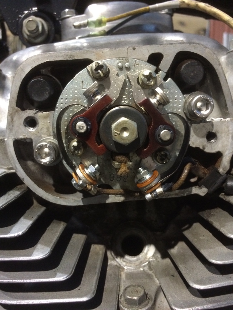
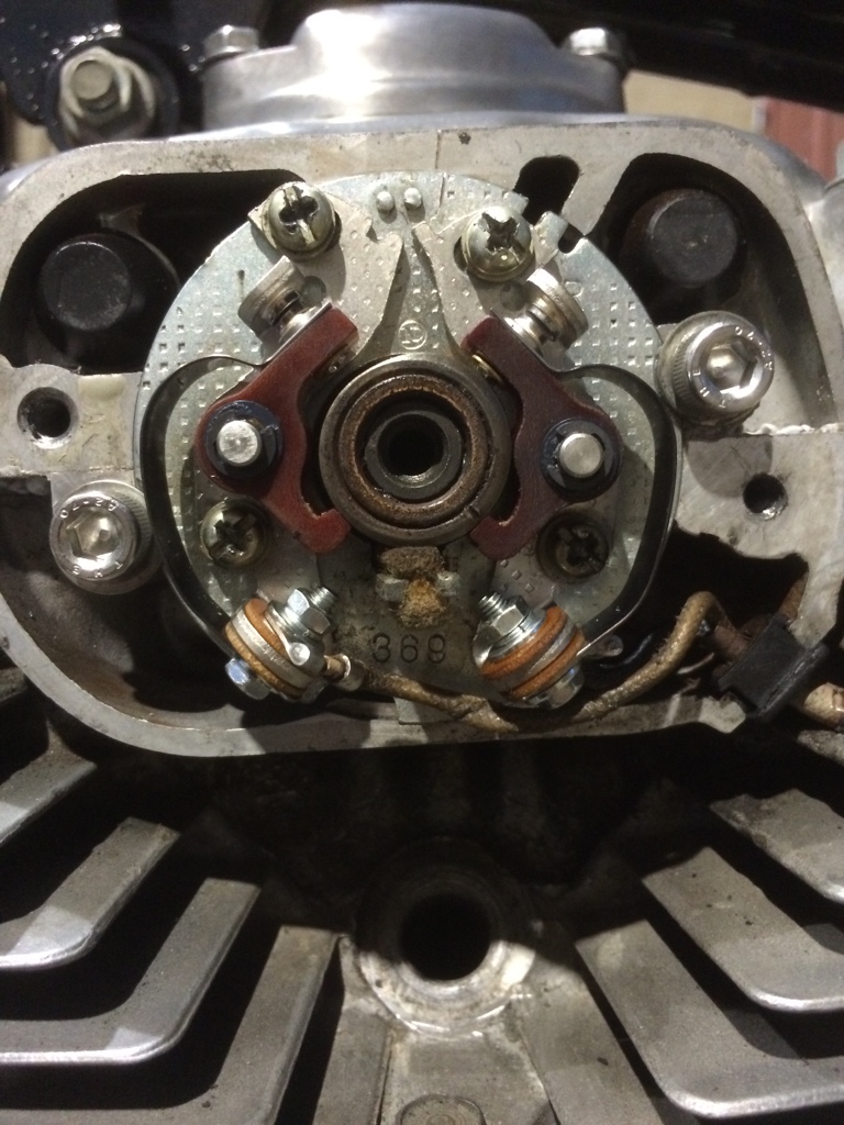
Wasn't going to replace the points but upon closer inspection the pitting calls for a fresh batch. I followed directions on setting the points and I'm a bit confused. The prior owner marked the point plate and surround (see etched marks in photo at top of plate) for alignment but when I follow the instructions I end up with the below. Does this look too cocked to anyone? And why would the dashes suddenly not align?
Sent from my iPhone
Sent from my iPhone
frogman
'74 CB360, '71 CB450, '75 CB550SS
That plate is way to far turned, the right side wiring will hit the cover when you put it on and ground that mess out.
Ignore PO's mistakes when you can, you need to start from fresh every time you touch or remove the point plate.
Start by centering the red circled tang thingy with the blue circled notch in the housing, if you start from where the PO marked the housing you are OFF.
Then remove the bolt and washer from the point cam and use the line or dot, line that up with the LEFT point FOOT and set its gap to middle of the range, IE .014" Leave the right side alone. I'm guessing that dot is what is circled in green.
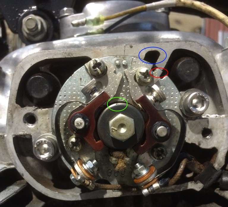
Then time the bike using the manual. When you finish timing the right side by gaping it you verify that that side is within the spec of .012-.016". No need to set it twice. If it is NOT in spec then start over from the top and reduce the size of the gap on the left side a bit.
Ignore PO's mistakes when you can, you need to start from fresh every time you touch or remove the point plate.
Start by centering the red circled tang thingy with the blue circled notch in the housing, if you start from where the PO marked the housing you are OFF.
Then remove the bolt and washer from the point cam and use the line or dot, line that up with the LEFT point FOOT and set its gap to middle of the range, IE .014" Leave the right side alone. I'm guessing that dot is what is circled in green.
Then time the bike using the manual. When you finish timing the right side by gaping it you verify that that side is within the spec of .012-.016". No need to set it twice. If it is NOT in spec then start over from the top and reduce the size of the gap on the left side a bit.
crazypj
Split personality, I fake being smart
The points plate is only very slightly turned, the outer 'slots' are for a flat blade screwdriver pry point
It will never run like that anyway, the insulating washers need to be between the spring/connector and backing, you have direct grounds with return springs on both plus connector on left side 8)
Also, it's a good idea to move the wiring connectors to the 'inside' under flat washer and on top of fibre one instead of under bolt head, gives more clearance when cover is fitted.
The 'dot' on points cam is for assembly of advance mechanism
mchltshcr
Active Member
This is helpful. I'm going to adjust the way the leads connect based on PJs feedback and I'll post an updated image.
I'm hesitant to rotate the plate back to the left because the high point on the points cam currently aligns to begin opening the left point contact right at the LF mark on compression. That said - I'm fine starting fresh following each adjustment and will need to do so as I adjust the lead connection.
Very MUCH appreciate the help.
mchltshcr
Active Member
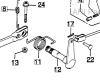
I am in need of the brake pivot shaft and brake pedal off a CJ360. Pedals are easy enough to find on ebay - shaft not so much other than 2 for about $25 shipped. Any help from members who have spare parts laying around is appreciated. I can paypal immediately.
It's part 12 in the attached. Thanks.
It's part 12 in the attached. Thanks.
Attachments
frogman
'74 CB360, '71 CB450, '75 CB550SS
I just tossed that out there as that is how I do mine, and I never have an issue with the plate going to much past that notch. Leaves plenty of room for adjustment, mine never grounds out on the cover either and I haven't used extra gaskets or filled the cover with silicone. Shop manual even shows pictures of the plate turned way back.
The dot and line on both advance units I have line up with the high point on the cam. So that's where I set my gap at, nice visual aid if you will.
Good catch on that left point though, I definitely didn't have enough coffee in me yesterday even after I blew that picture up.
The dot and line on both advance units I have line up with the high point on the cam. So that's where I set my gap at, nice visual aid if you will.
Good catch on that left point though, I definitely didn't have enough coffee in me yesterday even after I blew that picture up.
mchltshcr
Active Member
Adjusted per directions. Much better from what I can tell. Won't know until she's got juice.
Also, decided AGAINST a lithium battery for now. Picked up a fairly small AGM style batt for $30. Will see if I am happy enough with the aesthetics to not try and go smaller. Would rather run the bike on a battery I know is solid, tweak any issues with the system and then experiment with a lifepo battery down the road. When I finally plant that money tree. *sigh*
Sent from my iPhone

mchltshcr
Active Member
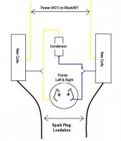
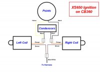
So I'm a bit confused. Went to wire up my ignition with xscoils and this is the breakdown:
My condensor has a yellow and blue wire
My points have a yellow and blue wire
My new mikesxs coils have a single yellow and single black each
None of that corresponds to the diagram.
EDIT: Did find another post breaking this down - realize I apparently need to add a dual connector to each coil.
My condensor has a yellow and blue wire
My points have a yellow and blue wire
My new mikesxs coils have a single yellow and single black each
None of that corresponds to the diagram.
EDIT: Did find another post breaking this down - realize I apparently need to add a dual connector to each coil.
Attachments
mchltshcr
Active Member
Made a two to one connector for both coils.
Blue from condensor and blue from points go into female black on right coil.
Yellow from condensor and yellow from points go into female black on left coil.
Single yellow male from each coil goes into factory black/white double female.
Sound accurate?
Sent from my iPhone
Blue from condensor and blue from points go into female black on right coil.
Yellow from condensor and yellow from points go into female black on left coil.
Single yellow male from each coil goes into factory black/white double female.
Sound accurate?
Sent from my iPhone