
We noticed you are blocking ads. DO THE TON only works with community supporters. Most are active members of the site with small businesses. Please consider disabling your ad blocking tool and checking out the businesses that help keep our site up and free.
You are using an out of date browser. It may not display this or other websites correctly.
You should upgrade or use an alternative browser.
You should upgrade or use an alternative browser.
1972 DS7 The Row Boat
- Thread starter clem
- Start date
50gary
Under the Limelight
Good on you Clem, keep nibbling away. I too must confess to letting life get in the way. I had a pretty serious work related accident (not my fault)with too much blood on the outside of my body. I'm fine but the bills just keep coming. Anyway stick with the bike it's cool and worth finishing.
Cheers, 50gary
Cheers, 50gary
Thanks for the words dudes. Just to note, I was able to shift through the gears before I buttoned up the engine completely with the clutch basket and oil pump so hopefully this weekend I'll get it cranked up and try to get around the neighborhood with it. I'm going to fill my argon bottle tomorrow and get after that seat too.
So far it looks like it is going downhill. The bike won't shift into gear with the R6 shifter. I put the original long shifter on it and it still wouldn't shift. It did engage a gear but only when I would keep my foot on the shifter. Looks like the stator side crank seal is leaking along with the clutch pushrod seal. That freakin sucks! Seems like if you can't buy OEM your stuck with wading through the crap that's reproduced. Looks like an engine rebuild is in the near future. I do have a set of RD350 cylinders on hand so I may as well get those bored out and put on the bike while I'm at it. Did I mention that the base gaskets are leaking too?

50gary
Under the Limelight
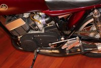
Clem, I was noticing the shift linkage and for me I always set the trans lever (short one) 90 degrees to the push rod (long one) that way you always get the most direct action, up or down shifting. For your setup it looks like you should shorten the push rod, maybe .75" .375" on each end (just guessing the inches from angled pic)
Cheers, 50gary
Cheers, 50gary
+1 50gary. There are two main things to consider. First, original lever length. Obviously if you just moved the pegs back a few inches, and also shortened the lever to match, the "leverage" would be so greatly reduced you probably couldn't shift the trans. This of course applies equally to your set up with a linkage. If the lever you borrow from a different bike or fab from scratch is shorter than stock, you have to make up for it by a shorter pedal belcrank lever and a longer shift shaft lever. So in concept, if your lever is half as long, delivering half the leverage, you make up for it by making the ratio of the belcrank and shift shaft levers 1:2. This is actually more complex because the result also is a function of radius vs degrees of rotation, but suffice it to say don't make any of the levers too short, which has a secondary benefit. Because there is always lost motion at any pivot, the longer the lever arms are, the smaller percentage of pedal slop manifested by that lost motion. Imagine a super short belcrank with a 1/16" of lost motion in the rod end or clevis. that would result in a lot of rotation before taking up the slack compared to an extra long belcrank. the second thing is the angle between the various levers and rods. Think of each lever as a crank. When the angle between the crank arm and the rod it is pushing is 90 degrees, you get the most distance traveled for each degree of rotation. It is also the point of least mechanical advantage, so it offers the least power applied. This works backwards when it is the rod pushing the crank, which is now the shift shaft lever, so it balances out for the most part. The trouble arrises when you have a situation when there is a different angle at the ends of the rod. Lets say you have 90 degrees at the belcrank, but the rod is too short to have 90 degrees at the shift shaft. When you lift up with your toe, you are at the weakest point of rotation, but at the shift shaft, the farther you pull the harder it gets because the farther around the shift shaft lever rotates, the worse the mechanical advantage gets. So up shifting will be really bad. Downshifting on the other hand, will be extra good, because as the belcrank rotates forward pushing the rod, it also rotates the shift shaft forward bringing the angle between the shift shaft and rod closer to 90 degrees improving the mechanical advantage.
I have scratch built a LOT of rear sets. To simplify, I suggest tho following.
1) figure out where you want your pegs to be and put them there.
2) now you can sit on the bike and figure out where the pedals need to go. that is the pedal at your toe, not the pivot.
3) If you can make the pedal the same length as stock, it will make things easier, but if you can't, you will have to compensate by belcrank to shift shaft lever ratio. This is the case for your DS, as you have chosen a pedal that is shorter than stock. Your belcrank will need to be shorter than your shift shaft lever the right amount to compensate.
4) pick the pivot location. This is a bit tricky. On the one hand, you rotate your foot like the peg was the center of rotation, but on the other, your foot actually rotates around your ankle, so above and behind the peg is optimal. Fortunately this seems to be much less critical than it would seem. Your stock pivot is the shift shaft, behind and below the stock peg and works fine.
5) Create a connecting rod. Make it the same as the distance between the shift shaft and the pedal pivot. Make it adjustable in both directions, but this will be very close to the best length. The adjustment is NOT to adjust the pedal height, though might serve to tweak it without disturbing the shift quality too much. Don't plan on it though.
6) Now you can determine the angle the belcrank arm needs to be in relation to the pedal lever. I'm sorry to say this is a problem for you because it is not adjustable. Solutions are to cut and re-weld it in the right place, or do likewise to the pedal, or bend it. This is the hazard with using parts intended for a not similar bike. Regardless, the shift shaft lever and the belcrank arm should be parallel to one another, and the angle between each of them and the connecting rod should be as close to 90 degrees as possible. This can not be the case if the two arms are parallel, but split the difference to have them both off the same.
The result will be a good functioning mechanism assuming the pivot axles are parallel, the mechanics are good etc. From there, you can fine tune by adjusting the rod length and spline location for the shift shaft lever, but you should be pretty close to optimal.
Here is a pic of a set up that works very well. Sorry you can't see it at a good angle, but the pedal is short, the belcrank arm is at 90 degrees, the shift shaft arm is longer than the belcrank, and the spline on the shift shaft is one forward of parallel with the rod adjusted longer to reach it. this gives the most power for upshifts, where your foot is weakest, and missed shifts are most common as a result.
Keep up the great work, and don't get discouraged working on the controls. They are deceivingly simple looking, but take a bit of pondering to get to work really well.
Attachments
wow that is a great 'splanation I have tried to convey the same message but never so well as you have
just to ad something for the brake side the 90 degree of moment should be in the range of when shoes are applied
oh and clem you still need to do vertical support on that upper shock bolt what you have now is very lkely to fail,too much leverage cantilevered out just hanging there
just to ad something for the brake side the 90 degree of moment should be in the range of when shoes are applied
oh and clem you still need to do vertical support on that upper shock bolt what you have now is very lkely to fail,too much leverage cantilevered out just hanging there
I knew that the arms needed to parallel so that's why I put the original shift lever back on the bike to try and get it to go through the gears. This still did not work. I will probably wind up cutting the linkage arm shorter and re threading it to get the correct length. I took the clutch off to check on the shift drum and it looked like the shift pawls were getting hung up on the shift drum pins. There is a v-shaped piece that sits on one side of the drum to allow these pawls to rise up over the pin, it looked distorted so I swapped it out with one off of a RD400 engine I have apart. It seemed to work on the stand but I took it back out and would only get into second gear on the street. I am going to split the cases again to make certain that I put the transmission back in the proper order.
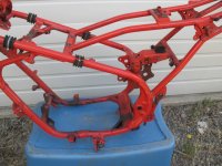
xb, I'm not trying to be an idiot about this bike but why do you think that the upper mount will not last very long? I used the calculation sheets from our structural engineering department for torsional stress and it appeared to be up to par with the stress placed on that particular member. In all reality adding another support would just transfer the same stress to another member of the frame that may not be able to handle what is being imposed. Upfront I did realize that no matter what I do to this bike that no part of it was ever intended to support a monoshock of any sort.
xb, I'm not trying to be an idiot about this bike but why do you think that the upper mount will not last very long? I used the calculation sheets from our structural engineering department for torsional stress and it appeared to be up to par with the stress placed on that particular member. In all reality adding another support would just transfer the same stress to another member of the frame that may not be able to handle what is being imposed. Upfront I did realize that no matter what I do to this bike that no part of it was ever intended to support a monoshock of any sort.
because of the way it hangs out in thin air it will be constantly flexing,at the weld joint,which leads to breakageclem said:I knew that the arms needed to parallel so that's why I put the original shift lever back on the bike to try and get it to go through the gears. This still did not work. I will probably wind up cutting the linkage arm shorter and re threading it to get the correct length. I took the clutch off to check on the shift drum and it looked like the shift pawls were getting hung up on the shift drum pins. There is a v-shaped piece that sits on one side of the drum to allow these pawls to rise up over the pin, it looked distorted so I swapped it out with one off of a RD400 engine I have apart. It seemed to work on the stand but I took it back out and would only get into second gear on the street. I am going to split the cases again to make certain that I put the transmission back in the proper order.
xb, I'm not trying to be an idiot about this bike but why do you think that the upper mount will not last very long? I used the calculation sheets from our structural engineering department for torsional stress and it appeared to be up to par with the stress placed on that particular member. In all reality adding another support would just transfer the same stress to another member of the frame that may not be able to handle what is being imposed. Upfront I did realize that no matter what I do to this bike that no part of it was ever intended to support a monoshock of any sort.
i don't understand how you cannot see that
Happy to help. I was worried that my long windedness would get me the boot! Actually, I also have concerns about your shock mount. Aside from reinforcing it, I am hoping you will perform super vigilant inspections once you are riding regularly. Back in a former existence, I made my living "rescuing" failed structural projects and getting them back on a solid science backed track. Some of that was some fairly serious race car stuff, where things break like you can not imagine. I see where the basic setup you are using is much like the original application, but the mount is longer, offering very substantially increased leverage on the DS tube, which was not intended to ever be loaded with such a tremendous torsional component like the bike the swingarm comes from. My "eagle eye" engineering assessment is that the very high loads and cyclic torque on that cross tube could cause it to fatigue and fail. It is possible it could go something like this: After some period of time (after you have stopped worrying about it) the constant tiny flexing causes an area to work harden and develop a crack. It is a hairline crack and not visible to the naked eye. The super attentive owner might notice an odd rusty dust there. Not long after, the crack continuously grows, faster, then a lot faster. As it gets weaker, the process accelerates and soon the structure is totally overwhelmed. That sort of failure usually goes from totally ok, to "I detect something" to catastrophic failure REALLY rapidly, as in moments after the "I notice something" epiphany. I envision the possibility that if it does fail in the typical fashion, you may be going faster than parking lot speed, in which case that sort of failure will likely be severely unpleasant, being such a super critical element. I mean, what will be the result if the mount does in fact give up fairly suddenly? Don't get me wrong, If you have competent people saying it is ok, who am I to say otherwise. I have not seen it in real life, and have not actually analyzed it knowing the alloy and section of the original tube and dimensions of all the elements. My assessment is strictly an observation based on experience. I usually don't worry too much about people making things, but when it looks like possible failure might bring about serious consequences, I would rather cry wolf that not try to prevent an accident. I suppose the good news is that that old DS chassis is made of some really mild "not prone to fatigue cracking steel" and like
xb says, the weld will be the source of the stress riser, so if the worst happens, you hopefully will have enough notice to take action. Anyway, if you decide you have confidence in it, please keep a sharp eye on it!
xb says, the weld will be the source of the stress riser, so if the worst happens, you hopefully will have enough notice to take action. Anyway, if you decide you have confidence in it, please keep a sharp eye on it!
+1. The issue is really that the mount is cantilevered and very long. It will generate a huge rotational (torque) that the tube ws not designed to withstand.
There are some fairly easy ways to change that. If you look at an RZ frame which is similar in general shape, you can see that they basically tied the rear (shock mount) frame tubes forward to the cross tube. To replicate that in design at least, you would need a cross tube (curved) across the rear tubes and a similar mount to the current one, tied back to the new cross tube.
OR
Tie that existing mount vertically into the rear of the tank area
OR
There are other ways, but you get the general idea.
Teazer I definitely will look up the RZ frame to find some pics and check out that design. I do know that the upper mount will generate a rotational torque on the tube, That's why I did the calculations starting from the rear axle to the linkage, through the spring then onto the lever to find out how much torque would be applied onto the tube. I ran the calcs from 1" of spring compression up to 3" and found that all were within bounds. One variable that I will admit that I do not know is the actual condition of the inside of tubing. I did consider changing that out with a new tube and I may still do that before the bike is completed.
Looks like I found the shifting problem. For some odd reason I found the need to disassemble the shift drum. Number 7 was in the wrong place. I caught it when I was double checking the function on a RD400 engine that I have torn down.
I still need to replace the new stator side crank seal. I am assuming that this can be done without splitting the cases back apart. The bad part about it is that I have to go through the motions of setting the timing. It wasn't a bad process but I am at the point to where when I'm done with something, I want to be done!
I still need to replace the new stator side crank seal. I am assuming that this can be done without splitting the cases back apart. The bad part about it is that I have to go through the motions of setting the timing. It wasn't a bad process but I am at the point to where when I'm done with something, I want to be done!
Attachments
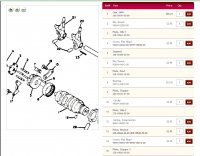
the stator crank seal has a ridge...so the cases need to get split...


