
We noticed you are blocking ads. DO THE TON only works with community supporters. Most are active members of the site with small businesses. Please consider disabling your ad blocking tool and checking out the businesses that help keep our site up and free.
You are using an out of date browser. It may not display this or other websites correctly.
You should upgrade or use an alternative browser.
You should upgrade or use an alternative browser.
1971 CL450 build. (not fancy, but complete...)
- Thread starter sleazy
- Start date
sleazy
"everyone has a plan…"
Thanks. yeah, i cant wait. It's difficult when youre making all these plans, ordering parts, sending things out, finalizing paint schemes, etc etc etc.. all weeks/months in advance. Then you set about the process, half-forget the things you set in motion... but when pieces start rolling in (and the decisions were good)- then the magic starts.
sleazy
"everyone has a plan…"
so i get up sunday after a late morning nap, wander out to the garage -and thought i'd rough in one side of the head to figure out all the little details/tricks and then let the kid do the other side (with a few hints and a little guidance.)
(before i continue- just understand that we bought the bike as a mess. never rode it, had no experience with this exact make and model, and the only contact we've had with it was in teardown... which is often messy, too quick and overwhelming. sometime you take something apart and do not pay enough attention to some little detail that no one in their right mind would pick out unless they had done it before.)
with that said, I sat down to put the head together...
anyone reading this forum is probably intimately familiar with this graphic:
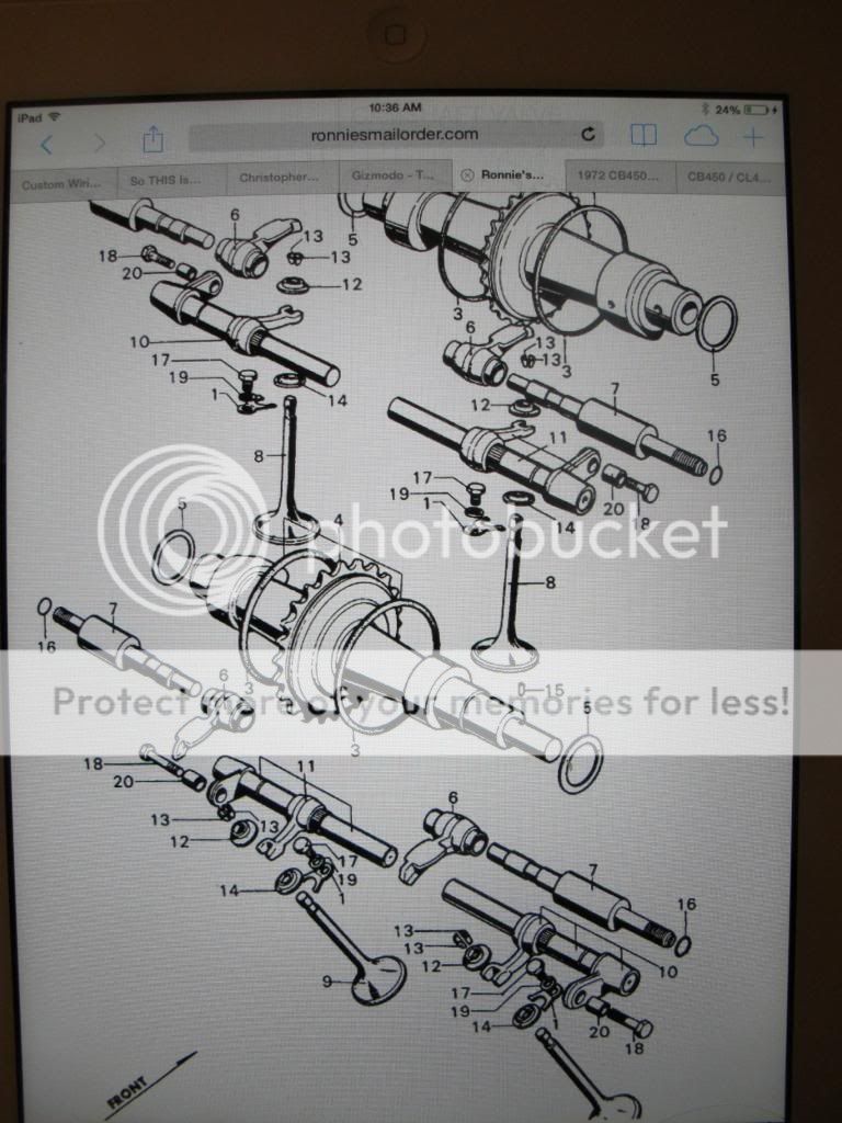
well, i sit down, assemble the valves, the torsion bars, the rockers out of their labeled ziplock bags... all is well. I pick up the cam and..
it doesnt fit.
i remember them being little bastards to get out (because we could not turn motor to relax the cam as cyclinders/pistons were rusted together) so initially, the difficulty didnt concern me. I just had to find the right angle to slide them in.
remember the above schematic? look reeeeeal close at the little arrow in the lower left hand corner.
see it?

the arrow points to the "FRONT" , which shows (for lack of a better description at this point-) the extra long cam goes in at the -opposite of the arrow- or, the BACK.
take another look at the schematic. and at the arrow. it shows the exhaust cam going in the "back" or intake position.
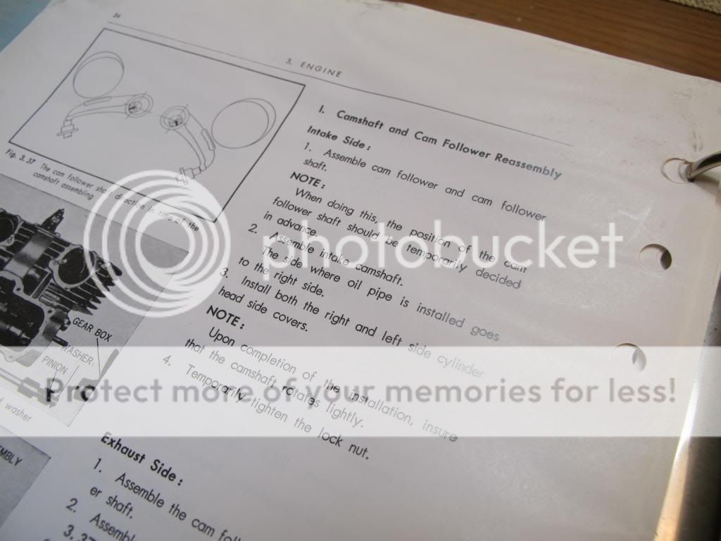
furthermore, the 45yr old, original, translated from Japanese technical manual is almost useless with its blurry black and white photos and Jing-Grish transaltions.
so after about an hour, I finally sat back and thought back about the process. I remembered the point and tacho on the FRONT of the motor -which was in clear contrast to the factory schematic.
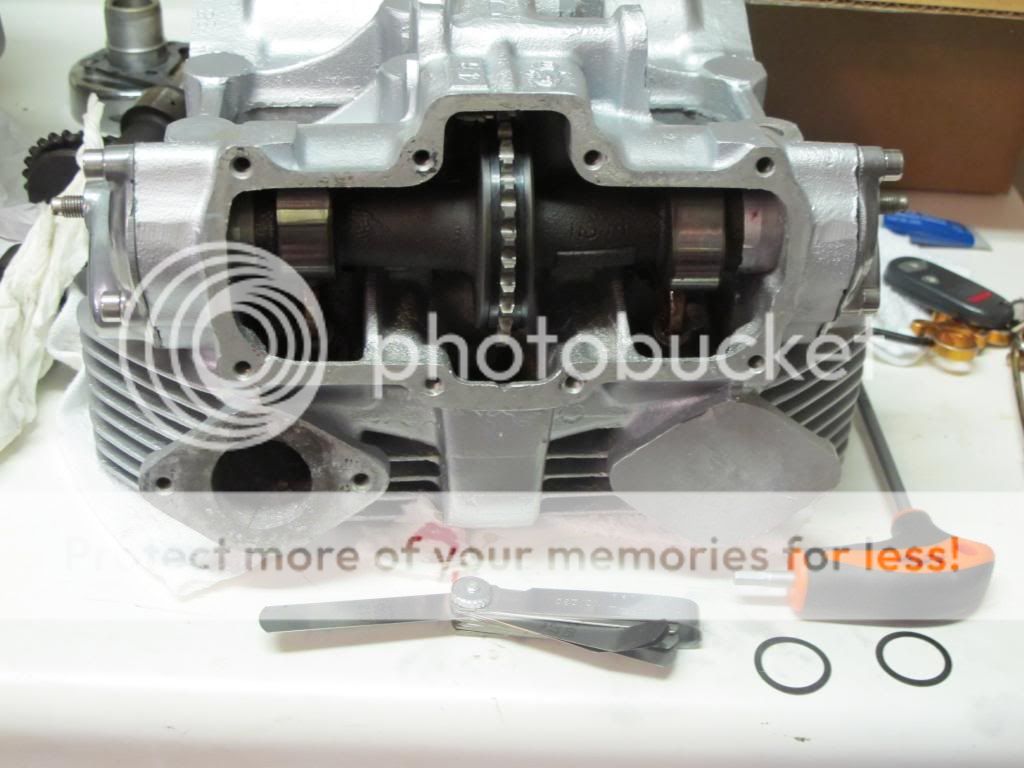
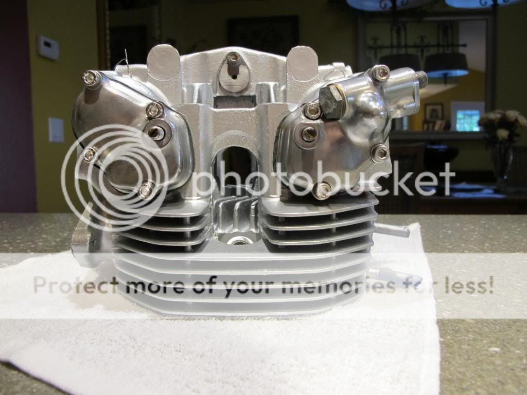
anyway, long story/short: finally got half the head together -with the right cam in the right place.
here it is mid cam-shimming.
and btw- Honda Twins has a GREAT sticky about the whole process here:
http://www.hondatwins.net/forums/1-project-logs/11792-cb450-cl450-valve-train-assembly-pictorial.html
a small hint for anyone reading to take from this. well, two actually: the first is- sometimes those that should know -dont.
second is: when tightening the valve holder caps, slowly/gradually torque only the three bolts that form a triangle in contact with the cam socket/cup. tighten the fourth (longer) bolt last. This ensures the holders go in straight and parallel and the cam will turn freely.
Tightening that longer bolt can put the slightest twist to the holder and bind the cam.
took me a few tries to figure that one out.
some chassis bits showed up! time to button up the roller.
(before i continue- just understand that we bought the bike as a mess. never rode it, had no experience with this exact make and model, and the only contact we've had with it was in teardown... which is often messy, too quick and overwhelming. sometime you take something apart and do not pay enough attention to some little detail that no one in their right mind would pick out unless they had done it before.)
with that said, I sat down to put the head together...
anyone reading this forum is probably intimately familiar with this graphic:

well, i sit down, assemble the valves, the torsion bars, the rockers out of their labeled ziplock bags... all is well. I pick up the cam and..
it doesnt fit.
i remember them being little bastards to get out (because we could not turn motor to relax the cam as cyclinders/pistons were rusted together) so initially, the difficulty didnt concern me. I just had to find the right angle to slide them in.
remember the above schematic? look reeeeeal close at the little arrow in the lower left hand corner.
see it?

the arrow points to the "FRONT" , which shows (for lack of a better description at this point-) the extra long cam goes in at the -opposite of the arrow- or, the BACK.
take another look at the schematic. and at the arrow. it shows the exhaust cam going in the "back" or intake position.
furthermore, the 45yr old, original, translated from Japanese technical manual is almost useless with its blurry black and white photos and Jing-Grish transaltions.

so after about an hour, I finally sat back and thought back about the process. I remembered the point and tacho on the FRONT of the motor -which was in clear contrast to the factory schematic.
anyway, long story/short: finally got half the head together -with the right cam in the right place.
here it is mid cam-shimming.

and btw- Honda Twins has a GREAT sticky about the whole process here:
http://www.hondatwins.net/forums/1-project-logs/11792-cb450-cl450-valve-train-assembly-pictorial.html
a small hint for anyone reading to take from this. well, two actually: the first is- sometimes those that should know -dont.
second is: when tightening the valve holder caps, slowly/gradually torque only the three bolts that form a triangle in contact with the cam socket/cup. tighten the fourth (longer) bolt last. This ensures the holders go in straight and parallel and the cam will turn freely.
Tightening that longer bolt can put the slightest twist to the holder and bind the cam.
took me a few tries to figure that one out.
some chassis bits showed up! time to button up the roller.
frogman
'74 CB360, '71 CB450, '75 CB550SS
Ah yes that schematic, I've spent many an hour staring at that thing. Matter of fact that manual is full of pictures like that.
How did the shimming go? When I put my head together the gaskets that I had purchased were so thin that with the bolts correctly tightened the cams would not turn at all!
Had to remake all 4 gaskets in thicker material which just managed to put clearance into spec without out shims.")
How did the shimming go? When I put my head together the gaskets that I had purchased were so thin that with the bolts correctly tightened the cams would not turn at all!
Had to remake all 4 gaskets in thicker material which just managed to put clearance into spec without out shims.
sleazy
"everyone has a plan…"
whew. i guess we were lucky. i just ordered a full engine gasket kit blindly off ebay. fortunately, the cam holder gaskets are quite thick. that would really suck to think everything is lined up and then have something like too thin a gasket hold you up.
one thing thats kind of odd- the manual and other places I've cross-referenced all say the cam clearance should be between .05 and .35mm. when your putting these things back together and dialing in that clearance… 1/3 of a mm is actually quite a lot. do people tend to run toward the tighter of that range or the looser?
one thing thats kind of odd- the manual and other places I've cross-referenced all say the cam clearance should be between .05 and .35mm. when your putting these things back together and dialing in that clearance… 1/3 of a mm is actually quite a lot. do people tend to run toward the tighter of that range or the looser?
sleazy
"everyone has a plan…"
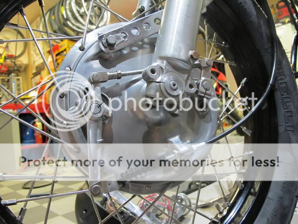
i was going to finish up the head tonight, but with the arrival of the clip ons, and with my partner mired in end-of-the-year exams he has to study for… i hit the garage solo to button up the front end.
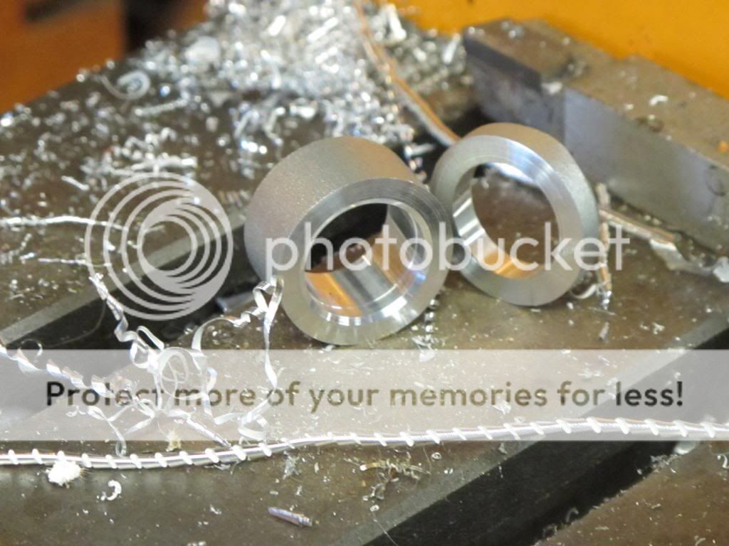
the bike was/is originally a CL. but the oddity of this particular years' fork tubes caused me to put a CB from end on it. for anyone else in this predicament, here is a small breakdown. CL forks are more closely spaced (width-wise) at the triple.
top is CB axle, bottom is CL:
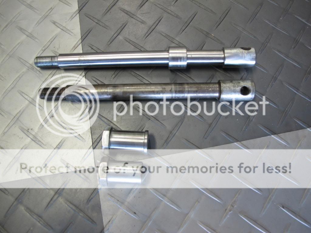
had to whip up a 5mm spacer on the lathe. found a left over 1.5" of aluminum dirt bike handlebar that i cut off. had to enlarge the interior hole diameter and trim it to length… but it makes excellent starting material.
got clip ons mounted, so could finally button up the front end. no more trial fittings. with everything in place, torqued down and adjusted- a small problem came to light:
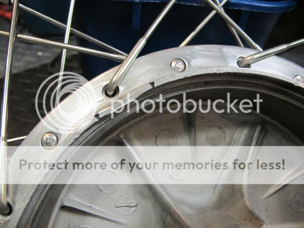
now i don't remember this happening anytime in my care, but the bike was pretty roached when I got it. preexisting? or did someone at Buchanan drop it on the shop floor? we'll never know. took a rounded punch and hammer and straightened the lip, then ground any inconsistencies.
so after a nights work- spacer got made, dented lip fixed, cable mounted and lever arms adjusted, bolts tight… i think the front end is done. now need to start thinking of a fender….
the bike was/is originally a CL. but the oddity of this particular years' fork tubes caused me to put a CB from end on it. for anyone else in this predicament, here is a small breakdown. CL forks are more closely spaced (width-wise) at the triple.
top is CB axle, bottom is CL:

had to whip up a 5mm spacer on the lathe. found a left over 1.5" of aluminum dirt bike handlebar that i cut off. had to enlarge the interior hole diameter and trim it to length… but it makes excellent starting material.

got clip ons mounted, so could finally button up the front end. no more trial fittings. with everything in place, torqued down and adjusted- a small problem came to light:

now i don't remember this happening anytime in my care, but the bike was pretty roached when I got it. preexisting? or did someone at Buchanan drop it on the shop floor? we'll never know. took a rounded punch and hammer and straightened the lip, then ground any inconsistencies.
so after a nights work- spacer got made, dented lip fixed, cable mounted and lever arms adjusted, bolts tight… i think the front end is done. now need to start thinking of a fender….

frogman
'74 CB360, '71 CB450, '75 CB550SS
sleazy said:one thing thats kind of odd- the manual and other places I've cross-referenced all say the cam clearance should be between .005 and .35mm. when your putting these things back together and dialing in that clearance… 1/3 of a mm is actually quite a lot. do people tend to run toward the tighter of that range or the looser?
I thought that number looked a little off, its .05 to .35 mm, but yeah that sounds like a lot until you think of what that size really is. Hard card stock like a business card is around .034mm so from there to the size of a piece of paper.
I chose to run mine where they ended up which if memory serves was right in the middle on the intake and slightly larger for the exhaust. Reading in a few places I think the reason for such a wide gap is to try to compensate for manufacturing processes of the day. Gaskets probably didn't come in very constant thicknesses so it was up the guy putting the engine together to get the clearances as close as possible. I've never heard of any reason to run the clearance in any point, just get it in the area and go on to the next step is what I have been told.
I DO suggest checking the clearance a few days after doing the initial set up, the gaskets will shrink under the pressure and make the clearance smaller. Probably another reason for such a large gap. ;D
sleazy
"everyone has a plan…"
thanks. thats a good hint about rechecking these things. also about them tightening up.
damn dog got me up at 5am, so wandered out to finish up the head.
intake cam set at .15, exhaust set to .21
i think that will do nicely.
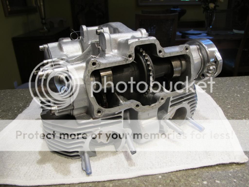
ps. ran a length of safety wire thru to help guide the cam chain when the time comes.
i want to paint the top fins black to match the cylinder, so perhaps head will go on and motor in this weekend?
damn dog got me up at 5am, so wandered out to finish up the head.
intake cam set at .15, exhaust set to .21
i think that will do nicely.


ps. ran a length of safety wire thru to help guide the cam chain when the time comes.
i want to paint the top fins black to match the cylinder, so perhaps head will go on and motor in this weekend?


sleazy
"everyone has a plan…"
some people have phobias. one of my personal points of concern is rivet-type master links. don't know why, can't explain it. i just prefer clip master links -i guess because its something you can check and confirm that everything is as it should be. with that being said- I'm posting photographic evidence in the case something lets go. maybe a karmic sense of due diligence, or something…
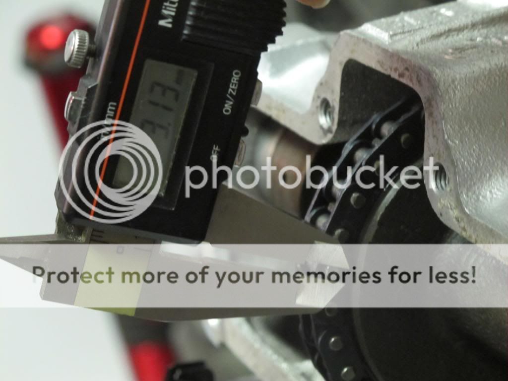
pic is not entirely clear- but here are the peen marks:
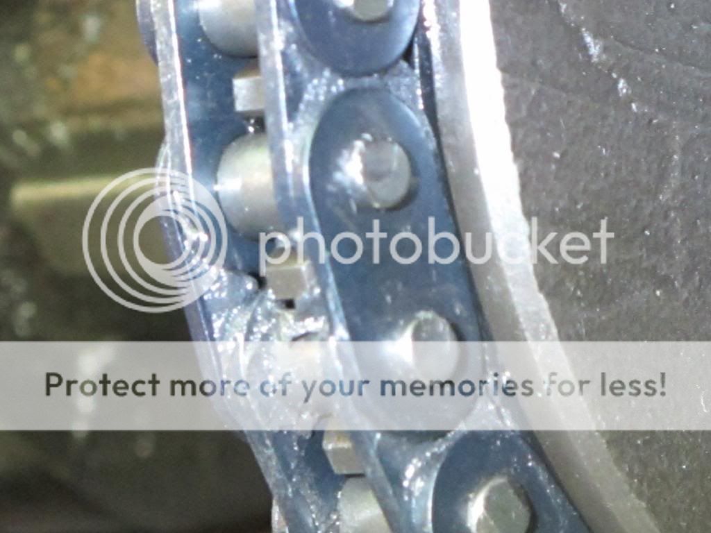
the rivet comes in about 2.91mm in diameter, once peened -i measure over 3.1. that SHOULD be good enough to give comfort/confidence to my psychosis.
pic is not entirely clear- but here are the peen marks:

the rivet comes in about 2.91mm in diameter, once peened -i measure over 3.1. that SHOULD be good enough to give comfort/confidence to my psychosis.


Flugtechnik
My bike is not transportation, it is a respite
Nice feeling isn't it. Wait until she fires up!
frogman
'74 CB360, '71 CB450, '75 CB550SS
Yeah I don't like those masterlinks either, the factory styles are so much easier to use and see that they actually mushroom like they are supposed to.
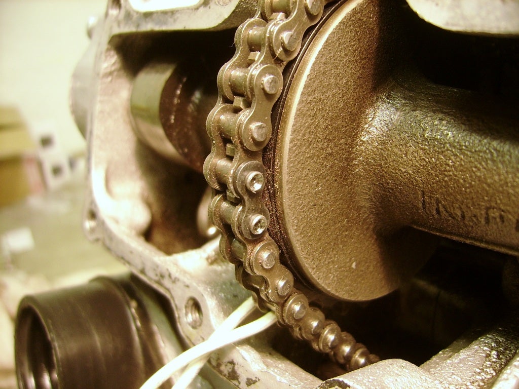
Factory masterlinks look like this when done, the ends are hollow so they just mushroom out nicely. I'm stealing this pic from a friends worklog.
Qucik check on ebay finds 2 of them as well in case you want to grab one now and replace it later on down the road doing a valve service.
http://www.ebay.com/itm/NOS-DID-219-CB450-Cam-Chain-Joint-Master-Link-Masterlink-14410-283-000-D-I-D-/121153807776?pt=Motorcycles_Parts_Accessories&hash=item1c355465a0&vxp=mtr
http://www.ebay.com/itm/Honda-CB350-CB450-CL450-CB750-camchain-master-link-DID-OEM-/261474631181?pt=Motorcycles_Parts_Accessories&hash=item3ce11a3e0d&vxp=mtr
Other than that, engine turned out beautiful!
sleazy said:some people have phobias. one of my personal points of concern is rivet-type master links. don't know why, can't explain it. i just prefer clip master links -i guess because its something you can check and confirm that everything is as it should be. with that being said- I'm posting photographic evidence in the case something lets go. maybe a karmic sense of due diligence, or something…
pic is not entirely clear- but here are the peen marks:
the rivet comes in about 2.91mm in diameter, once peened -i measure over 3.1. that SHOULD be good enough to give comfort/confidence to my psychosis.
coming along so nicely
you did real good on the peening you can over do it and cause damage to the link itself, the one frogman shows is overdone to the point of being questionable
there is next to zero forces or loads trying to peel it off in a running engine
carry on
sleazy
"everyone has a plan…"
thank you xb33bsa for the confirmation. i would whole heartedly rather use the hollow points like frogman pointed out. next time.
well, here's where the swearing started. I think my kid learned a few to add to his personal "blue" vocabulary this afternoon.
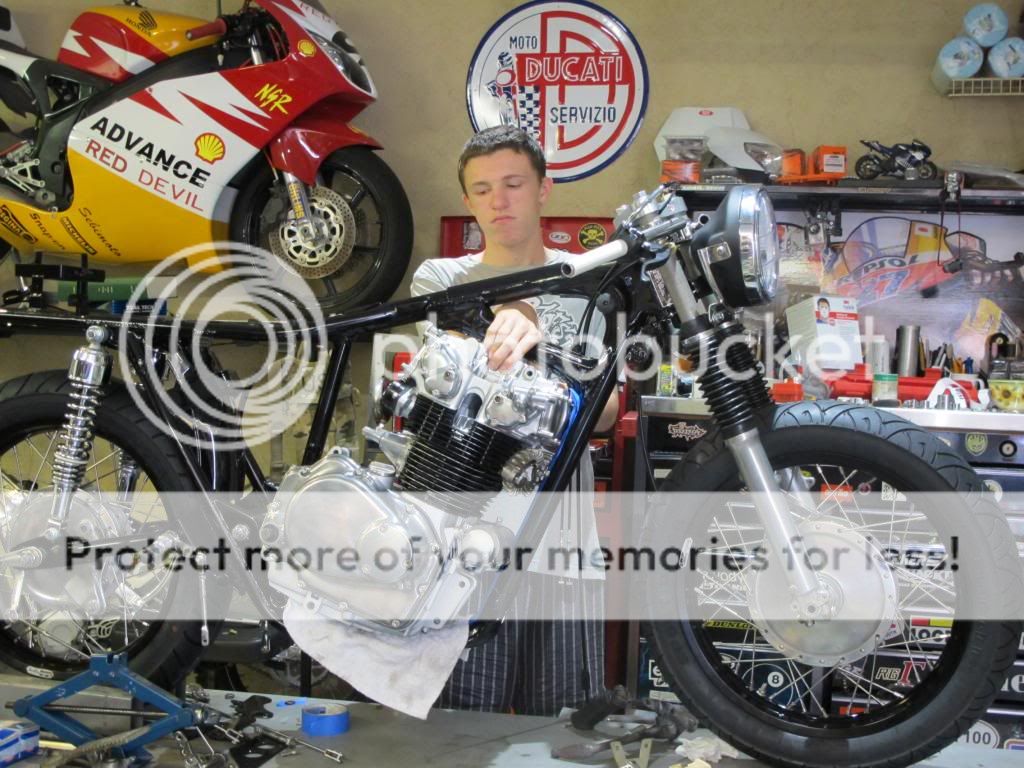
in retrospect (and now that's in)- it looks as if it might have been easier to take out/put in from the left/clutch side. (what was that about Crumbaugh's law?)
anyway- for a bike with that big a opening in it, there is surprisingly little room for getting the motor lined up.
this thing is like building a supermoto bike…. you see it done 1000 times, but there are just some things that pop up that you assumed too much on.
take for instance the rear shock length. you solve one problem -the tire/suspension travel clearance- and you create another. namely, chain rub on the swing arm.
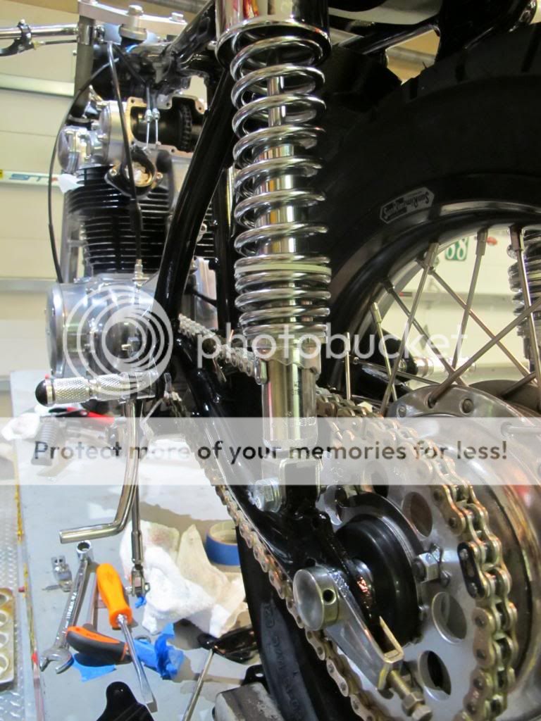
there's just enough to pass with a good and well placed chain guide, but i think one of the finishing details will be with bigger sprockets for a little more room.
tonight, a good garage clean and put back/sort all the tools. tomorrow we'll rough in the tank and seat and wheel her out for some pics.


