cb360 wiring harness

360noob

New Member
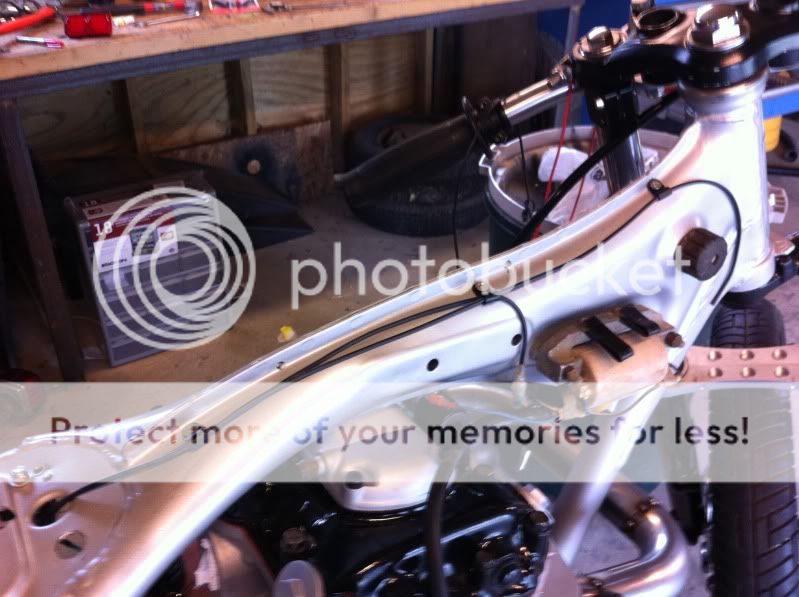
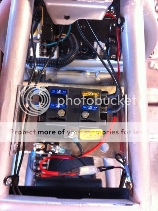
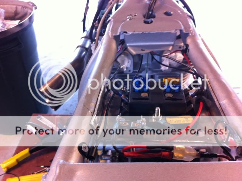
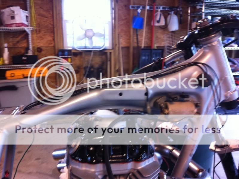
my 75 cb360 had a pretty thrashed harness when i stripped the bike down..i have a complete diagram and ive always been really good with electronics and wiring ...has anyone built their own harness from scratch like i plan to do ? any tips or pointers would be greatly appreciated
 
A couple people have. Google a site called "vintage connections" and also the wiring diagrams on www.oldmanhonda.com. Both are a huge help.

Oh- I meant the interactive diagrams on oldmanhonda.
 
I did the harness on mine. The single most important thing you can do is to properly diagram what it is you're trying to do. After that, mockup all your runs and connections before trying up your harness in electrical tape (or similar).
 
your not building a wiring harness for a custom application so it is pretty much copy the wiring diagram- if custom then you do want to draw a schematic that should go with the bike...you may be able to eliminate runs not used on your bike if there are any. use good connectors/insulators- not those god awful red and blue cheap ass connectors. use good harness tape,sheathing and heatshrink. solder ground wires and battery terminals..and if a length of a run is in question leave it longer and finish it on the bike were you can be sure..that has worked for me on custom applications...joe@ vcycle
 
I did the same or similar as Sonreir, drew it up and laid it out. I am running lights constantly, with kick only so it is as simple as you can get.
Here are a few shots

Joe- dont worry, I swapped all my cheap blade connectors for good ones ;)
66.jpg

70.jpg

71.jpg

72.jpg
 
Dstew- Sure thing, I will transfer my paper one on to the computer for you and post it up.
 
DStew-

Here you go. I have since wired in an additional switch to turn on and off the headlights, also I am using a battery eliminator instead of a battery (wires in the same)
Untitled-2.gif
 
I love the simplicity of your wiring diagram shocwav

Is that bike completed/running? Have you had any issues with the wiring so far.
If not, I will be using/copying it for my 360 build.
 
vtwin650 said:
I love the simplicity of your wiring diagram shocwav

Is that bike completed/running? Have you had any issues with the wiring so far.
If not, I will be using/copying it for my 360 build.

Bike runs and charges, no issues. I did add an on/off for the headlight since the bike is a kick only with no battery. The 650 I am building will utilize a common ground point but otherwise it will be the same wiring as my 650.
 
Thanks for that diagram!!! HUGE HELP! one thing though, each line on that diagram represents one physical wire correct? I am super noob at electronic type things like this and it all seems so complicated, I got 3-4 wires coming out of on piece, say regulator, which do I need and which can I lose?
you are awesome.
thx!
 
dStew said:
Thanks for that diagram!!! HUGE HELP! one thing though, each line on that diagram represents one physical wire correct? I am super noob at electronic type things like this and it all seems so complicated, I got 3-4 wires coming out of on piece, say regulator, which do I need and which can I lose?
you are awesome.
thx!

No worries man. That is correct each line is an actual wire. Black is positive in the diagram.
 
shocwav3 said:
DStew-

Here you go. I have since wired in an additional switch to turn on and off the headlights, also I am using a battery eliminator instead of a battery (wires in the same)
Untitled-2.gif

Is it possible for you to take some close up shots of your bike and the connection points? I am getting ready to wire mine up this weekend using a battery but will be adding a momentary start button and 3 position (center off) headlight switch. Would it be to much trouble to ask you to add the start button to your diagram?
 
I'll have a look at what's going on with my situation and get back to you for the questions Im sure I'll have, haha!
 
bananaclip said:
Is it possible for you to take some close up shots of your bike and the connection points? I am getting ready to wire mine up this weekend using a battery but will be adding a momentary start button and 3 position (center off) headlight switch. Would it be to much trouble to ask you to add the start button to your diagram?


Banana- So you want to see the starter and a button style switch included correct?
Its no problem, I will work it and post it up when Im done.
 
What about your condenser, points, and regulator? I have all those parts in my heap of electronics from the original harness, where do those come in to play? Is it really as simple as this diagram? It seems like it needs to be so much more complicated than that... And what do I do with all the extra wires coming out of some of the pieces like the rectifier? It's got 4 wires coming out of it...ugh. :(
 
dStew said:
What about your condenser, points, and regulator? I have all those parts in my heap of electronics from the original harness, where do those come in to play? Is it really as simple as this diagram? It seems like it needs to be so much more complicated than that... And what do I do with all the extra wires coming out of some of the pieces like the rectifier? It's got 4 wires coming out of it...ugh. :(

Dstew,

A regulator would be a simple addition in line from the power coming from the rectifier to the battery (or the red exiting the rectifier and entering the battery) I am not running one since I am essentially using period correct lighting (which is not as susceptible to over amperage the way LED's and electronic ignition are) If I was running ANY modern electronics I would be running a regulator. As for the 4 wires coming from the rectifier..if you look closely at the diagram I posted I am utilizing all 4 of those wires. (more specifically I am running yellow from the rectifier to the white and yellow from the alternator, pink to pink, green is ground and red is the hot lead back to the battery) Next lets talk about the condenser and points. Power enters the coil via a power lead from the fuse block, from each coil you have a lead color coded to pig tail into both the condenser and regulator(another words match up the blue lead from your condenser and the blue lead from your points and plug it into the blue lead from the coil, follow the same process for the yellow leads) The color coding helps maintain order when the bike fires, coil fires plug in specific cylinder and sends a signal to the point on the proper side.

The whole diagram might be clearer if you picture if with the flow of electricity and how the bike is essentially powering itself, at least that helps me understand diagrams.

I assure you it really can be this simple, I run my bike on it and have run a few others off this exact diagram without any issues, that being said there are a million and one things that could complicate it in a heartbeat (blinkers for example) but this is the bare bones and it works just fine.

If you want I can add the items we talked about, along with a few arrows from flow and some notes, Believe me I understand it can be daunting. The first car I wired I wanted to give up about 400 times..
 
Bannana-

I didnt forget about you, I am sorry it took me so long. I dont even know if you still need this.
starteradded.gif

I actually had to look at a stock diagram because I havent seen a starter wired on a bike in quite some time.

And just for clarification, all the black leads are power.
 
Back
Top Bottom