1977 Honda CJ360 - Café SOS - Stage Two™

Rich,

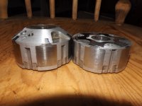
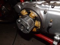
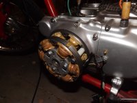
An electromagnetic alternator would be a nice swap and something I'm considering as a long term goal (or backup plan, if needed). That way, I'm only stealing as much horsepower as is necessary. It's something into which I am definitely investigating. In the mean time, I'm having the rotors turned down so they take up less space, and weight less, than they otherwise would. I've worked it out at about 1.5" longer than stock, and with some grade eight bolts (3x 8mm) holding the rotors together, I should be good to go.

The plan for the rearsets, at the moment, is to cut down the stock passenger "loops" (I saved them when they came off the frame, originally) and re-weld them to the frame. If I can't get that to work in a satisfactory fashion, I will definitely use your idea of a "box" made from some identical flat plates.

I'll have to look into mounting up my exhaust slightly differently. The new rearset mounts might make for better looking lines.

-Matt
 
My original plan was to weld tabs to the frame where the passenger loop was and make rear sets and head light ears painted to match the frame.


Then I got lazy and used the pass loops and bought the headlight ears.


See the pic - this was what I was planning on doing for the rear set plate, I just never go around to getting the round pieces machined.
 

Attachments

  • head light.jpg
    head light.jpg
    198 KB · Views: 312
Hi Sonreir

Regarding your wiring diagram, I notice that you have no battery in the circuit. I am rebuilding an XL185 for paddock bashing. It has CDI ignition and kick start. As I have no requirement for lights, indicators or battery if I disregard the lights and switches on your diagram (and obviously just one Reg/rect and alternator) and just go with the bare circuitry to provide a spark, would that work?

Also just out of curiosity what is your temperature sensor sensing? Oil temp?

Thx
 
If your system is self-generating you can go without a battery (many race ignitions are set up this way). The other way to do without the battery is to use a capacitor in its place, which is what I'm doing. This second option is only available if your alternator uses a permanent magnet, though. Electromagnetic systems require a battery to generate the magnetic field, which, in turn, generates your wattage.

The temp sensor is for head temps. It slips in between the spark plug and the head and works in conjunction with my dash computer (Trailtech Vapor Stealth) to provide an idea of how hot things are getting.
 
I got a little more done this weekend. Another set of brackers got the CAD ("Cardboard-Aided Design" --Rich) treatment and then welded into place. I still need to clean up some splatter before they're ready for paint. A trip to the hardwar store will be necessary for some spacers and longer hardware, too. Pretty sure this will work out, but I can stiffen it further by welding in some metal around the edges.

While I was messing around in the shop, I also deleted my "push" cable from the throttle assembly. I reused a bit of the hardware as a plug for the control assembly after melting some silver solder into it.

559658_10151307124660159_1298720380_n.jpg


559658_10151307124665159_284422197_n.jpg


559658_10151307124670159_1506352923_n.jpg


559658_10151307124675159_2044767074_n.jpg
 
Well... I think my Dad might be able to get ahold of something like that.

I'll have to remember to ask him for the following:

2x @ .25" ID, Length 1.0"
2x @ .25" ID, Length .5"
4x @ .313" ID, Length 1.0"

;D
 
Sonreir said:
Well... I think my Dad might be able to get ahold of something like that.

I'll have to remember to ask him for the following:

2x @ .25" ID, Length 1.0"
2x @ .25" ID, Length .5"
4x @ .313" ID, Length 1.0"

;D

In case you don't already know this site... www.mcmaster.com
 
OK... I finally got off my lazy ass and did something. I pulled apart the wiring harness and mounted up my new LED headlight. Total draw is 12W with the high beam on. Comes with running light, too.

It appears to be bright enough, but I'm unsure about the diffusion. I'll take a few more pics when it gets darker.

Up next is to alter the headlight ears as this headlight is about an inch and a half smaller in diameter than my old one.

I guess I should get around to painting my rearset mounts, too.
 

Attachments

  • DSCF2455.JPG
    DSCF2455.JPG
    495 KB · Views: 261
  • DSCF2457.JPG
    DSCF2457.JPG
    611.9 KB · Views: 269
  • DSCF2458.JPG
    DSCF2458.JPG
    596.7 KB · Views: 272
Thanks, man. I'm definitely pleased with it. I'm going to try to import a few more and I have a thread going in the Selling section if you're interested.
 
OK... I borrowed some of my neighbor's time and expertise and we used his lathe to turn down the original and spare rotor.

I've now got a setup that's mostly ready for use. Dual rotor and stator should boost the output by a fair margin. Fingers crossed this actually works. The unknown here is whether or not the stators and rotors will interfere with each other too much during operation.

Here's hoping...
 

Attachments

  • 2013-01-26 001.JPG
    2013-01-26 001.JPG
    384 KB · Views: 272
  • 2013-01-26 003.JPG
    2013-01-26 003.JPG
    350.8 KB · Views: 256
  • 2013-01-26 002.JPG
    2013-01-26 002.JPG
    353.9 KB · Views: 267
So are you going to put a threaded spacer in between your rearset plates or still try to run a nut and bolt? Another great source for metric parts if you've got the time to play around on their website is http://us.misumi-ec.com/. They have all sorts of configurable shafts and collars and such that often times end up being cheaper than custom machined parts.
 
Actually, I think I'm going to run some nylon spacers. I'm not sure that part needs to be threaded, but we'll see how it goes. After all this, I don't mind going back to the drawing board another time... lol
 
Back
Top Bottom