New Bedlam Werks build: 1999 Yamaha XT600

BedlamWerks

Custom motorcycle parts and aluminum fabrication
Our shop is starting a new build on a 1999 Yamaha XT 600. Just wanted to introduce the build and share a little of our design process. Let me know what you think - http://bedlamwerks.com/blog/81-newbuild. More info to come later.

Update: Here is the new link to our build progress - http://bedlamwerks.com/blog/83-buildprogress1
 
I dig these bikes and wouldn't mind picking one up one of these days. Following along...
 
Ok so we got some frame modifications in the works. We had to do a lot of clean up on the original mods and welds, and added on a newly built subframe we designed.
 

Attachments

  • IMG_3678.JPG
    IMG_3678.JPG
    5.1 MB · Views: 457
  • IMG_3661.JPG
    IMG_3661.JPG
    4 MB · Views: 428
Here is the link to our blog which describes our progress so far. http://bedlamwerks.com/blog/83-buildprogress1 Thanks for following.
 
Build Progress:
1/15/15

We did some brainstorming. Made the parts to attach/fit onto the carburetor by hand with the lathe. Then we planned out the shape for our airbox and ordered a filter to fit. Then we made the air box and attached it to the bike. Rather than just using perforated metal, we decided to drill the holes by hand to create an interesting and artistic pattern while reducing the number of parts that were made. We are currently working on the oil tank reservoir. Once we found out the volume required, we worked on making a shape that could fit on the bike and hold the right amount of oil. Travis made a pipe on the lathe for the interior to make sure the return oil enters the top of the tank. The next step would be to install that and make the final 4th side of the oil tank. When that is complete we will pressure test it and double check the volume.

1/28/15

Once we installed all the fittings on the outside of the oil tank and welded the inside so they would hold the oil, we then measured and cut the fourth side and welded it in place to the tank. Because we decided to put the oil tank on the front of the bike, we planned on putting some holes through it to let some air through to the motor to cool it and hoped it would also help keep the oil cool. After we had the fourth side welded in place, we double checked the volume of the inside of the oil tank and made sure once we put four holes through it, it would end up with the correct volume for the bike, which was correct. Next we drew the four circles on the front side of the oil tank and visualized where they would line up with motor and frame of the bike. When we were sure they were in the right place, we used a hole saw to cut through the oil tank and cut our pipe into four pieces and welded them in place. Next step was lots of filing to clean up the shape. The tank is now complete and is in the surface finishing stages (fine filing and sanding). We will need to figure out how we are going to mount the tank onto the bike and order oil lines to connect the custom tank to the motor. We also have the exhaust in place to make sure it will fit with the new oil tank and that will be our next step in composing the bike: Double checking where the fittings will go in relation to the exhaust. The exhaust will sweep around the motor, in between the frame and the mono shock on the back, and will come straight out beside the tire. We will soon order a muffler and fine tune the pipe so it will fit in the proper location. Right now we are hand fabricating a headlight bucket out of .090 aluminum, which will most likely be built so any instruments can be mounted onto it. After discussions with the client, we are beginning the process of building a custom gas tank, also out of .090 3003 aluminum, making it lighter than the original tank. First we will create templates from poster board and build a buck using MDF. The new tank will be slightly larger and will fit the space on the bike better because it will be specifically created for that space.

For more photos check out the blog at http://bedlamwerks.com/blog/83-buildprogress1
 

Attachments

  • IMG_4876.JPG
    IMG_4876.JPG
    4.3 MB · Views: 388
  • IMG_4903.JPG
    IMG_4903.JPG
    982.1 KB · Views: 278
Build Updates:
Stage 4 - 2/10/15

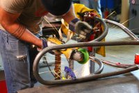
Starting with bristle board, we traced the original tank bottom and created a drawing of the side profile of the tank that we wanted to replace it with. The customer gave us freedom to use our imaginations and come up with a design that we felt would suit the look he was going for. Then we made a bottom plate with MDF and two MDF copies of the side profile drawing of the tank. These would be used as the basis for our MDF buck. The bottom plate of the buck is cut in half and one of each of the side profile MDF copies would be attached at a 90 degree angle to create the center line of the buck. This makes it so that our buck has two halves that can be clamped together to create the overall shape of the gas tank.

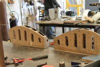
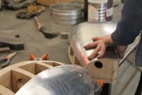
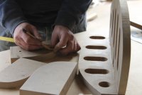
The next step was to create ribs which would define the volume shape of each side. To ensure symmetry, we drew one section at a time and traced it onto two pieces of MDF that had been screwed together so when it was cut, it resulted in two identical pieces. They were cleaned on the belt sander before we separated the two pieces. Next we drilled holes while the two pieces were still together to be able to clamp the metal to the buck and to allow us to look through and see if the sheet metal lined up properly with the contour of the buck behind it. These were glued and screwed in place, and then we moved to the next section. We repeated this process until we had an overall view of what the tank would look like. When choosing where each rib would be located on the buck, we kept in mind where the weld seams in the aluminum would be. For instance, where the shape changes dramatically, there will most likely be a seam in that place. The shape of the tank determines placement of the seams. We placed the ribs at the seams so they would be supported when we tacked the aluminum sheets together.

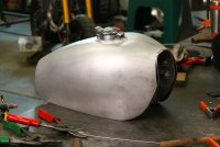
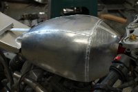
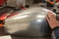
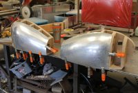
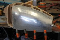
Once the buck was completed, we used bristle board to make detailed templates of each piece of aluminum we were going to use. We tacked on the template pieces to the buck until one side was covered. Then we traced each one twice on the aluminum so we had two pieces of each shape, one for the left and one for the right side of the tank. It’s a good idea to label these and each side of the buck to match to make sure you bend each piece to curve in the right direction. We separate the left and right side of the buck and placed them beside each other with the pieces of aluminum labeled in the appropriate spot beside each buck. When doing this, it is a good idea to go piece by piece, alternating as you go. For example, if you start at the front on the right buck, you probably want to do the left front piece next that corresponds with that on the tank. If it’s a convex or concave part, begin by hitting it with a hammer on a leather bag full of lead shot until it has the right curve, then use the English wheel to smooth out the hammer marks. Each time you do something to the piece, hold it up to the buck to see how it fits and choose the next step to make it fit more precisely. A good example of why you should work on two corresponding pieces at the same time is because if you have to make adjustments to one side, such as shrinking the edge, you can immediately do the same thing to the other side ensuring each one was worked the same way and keeping consistency on both sides. We worked the metal pieces until they fit and covered both sides of the buck, then we clamped each piece on as we finished them. Once they were all the right shape, we tacked them all together. Then we clamped/screwed the buck back together and tacked the two sides of the the aluminum tank together. It is important to make sure you tack all your pieces together before welding any seems because welding causes pieces to warp due to the shrinking of the metal. On that note, weld seams in lengths that correspond with each other on both sides, much like the alternating shaping of the aluminum sheet. Once we welded the whole top on the outside, we took it off the buck and welded the seams from the inside to ensure full penetration and prevent any leaking of gasoline.

Stage 5 - 2/27/15

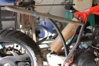
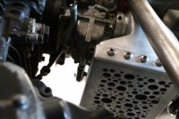
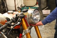
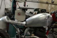
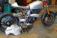
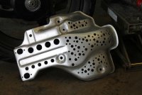
The next step was to make a channel piece that will attach to the frame and go through the tank so the tank can properly fit onto the bike. We gauged where the petcock was going to be a create vents and crossover that will allow gas to move from one side of the tank to the other while the bike is on it’s side kickstand. This was done separately from the tank and will be added on after so we can weld the inside and outside of the tank and all the attachments. After this is finished, we will test fit the tank top on the bike with the channel, tack it together, and weld the seams until we have a completed, enclosed form. This will be a good time to test for leaks using air pressure. Once it’s pressure tested, we begin finishing (filing, sanding, and polishing). Next we are making a box for underneath the seat that will hold the electrical components.

Please view the link to this blog here: http://bedlamwerks.com/blog/83-buildprogress1
 

Attachments

  • ksmith_progress_034.jpg
    ksmith_progress_034.jpg
    506 KB · Views: 282
  • ksmith_progress_032.jpg
    ksmith_progress_032.jpg
    510.1 KB · Views: 315
  • ksmith_progress_014.jpg
    ksmith_progress_014.jpg
    427.6 KB · Views: 284
  • ksmith_progress_033.jpg
    ksmith_progress_033.jpg
    564.9 KB · Views: 269
  • ksmith_progress_025.jpg
    ksmith_progress_025.jpg
    494.7 KB · Views: 288
  • ksmith_progress_024.jpg
    ksmith_progress_024.jpg
    569.5 KB · Views: 266
  • ksmith_progress_022.jpg
    ksmith_progress_022.jpg
    548.9 KB · Views: 312
  • ksmith_progress_020.jpg
    ksmith_progress_020.jpg
    428.5 KB · Views: 287
  • ksmith_progress_019.jpg
    ksmith_progress_019.jpg
    64.4 KB · Views: 254
  • ksmith_progress_015.jpg
    ksmith_progress_015.jpg
    401 KB · Views: 269
Am hooked on this build, great skills and an eye for detail 8) keep the updates comin guys :p
 
yorkie350 said:
Am hooked on this build, great skills and an eye for detail 8) keep the updates comin guys :p
settintrendz said:
Fantastic work guys.
Very well-built bucks as well
Im excited for the this one.
Thanks for all the support guys. Just finished making a skid plate this week. I'll have the new photos up soon. Happy Thursday!
 
Since my last entry, we have made a heat shield for the exhaust, mimicking the hole pattern from the airbox intake screen. We also cleaned up the skid plate and drilled a similar pattern of holes to be consistent with the rest of the design, and Travis machined new footpegs. We also ordered a new custom gauge, complete with our logo. Looking good so far! Check out the photos below. I’ve added a few more of the gas tank as well. Here is the full link to the build bio: http://bedlamwerks.com/blog/83-buildprogress1
 

Attachments

  • kevin_smith_stg6_005.jpg
    kevin_smith_stg6_005.jpg
    370.3 KB · Views: 270
  • kevin_smith_stg6_004.jpg
    kevin_smith_stg6_004.jpg
    225.7 KB · Views: 249
  • kevin_smith_stg6_003.jpg
    kevin_smith_stg6_003.jpg
    295.2 KB · Views: 261
  • kevin_smith_stg6_002.jpg
    kevin_smith_stg6_002.jpg
    221.1 KB · Views: 244
  • kevin_smith_stg6_001.jpg
    kevin_smith_stg6_001.jpg
    222.4 KB · Views: 254
  • kevin_smith_stg6_006.jpg
    kevin_smith_stg6_006.jpg
    221.9 KB · Views: 237
Back
Top Bottom