Either front or rear brake switches activates a connection from the brown wire circuit to the green-yellow circuit (which only goes to the rear brake light - yellow wire). The blue-red wire circuit (tail/aux light) gets power from the brown wire circuit through the right handlebar light switch and the main (keyed) ignition switch. If other lines are being powered from the green-yellow circuit (and they should not be according to your diagram) this might be the circuit to track down. Maybe something shorting in the tail light between the yellow and blue-red wires? Maybe something else somewhere along the green-yellow circuit? If this wiring diagram matches your bike, you should be able to use it and some simple electrical troubleshooting tools (12v light, beeper, multimeter, etc.) to chase down your issues. It just takes time, patience, good illumination, and a large print-off of the wiring diagram. BTW - this is why some have converted their bikes to a "minimalist" wiring harness.
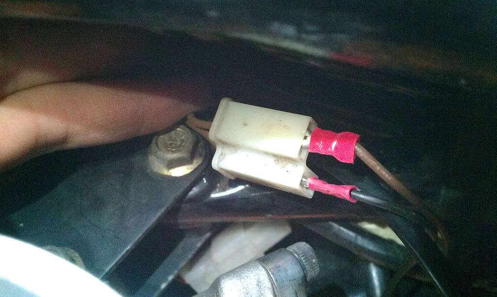
Using your multimeter - you can check out if all the switch positions are making connections to the various wire circuits as shown in the wiring diagram (I'd start with the handlebar light switch first and the ignition switch second). Measure for continuity (0 ohms) between the plug wires as shown in the diagram. Also check to see that ONLY the wire circuits indicated on the diagram are connected together (no continuity where the switch position is not "made" between wires). If you do not find the problem and want to go further, you can unplug harness connectors and check for continuity across each wire color group but I don't think I'd advise it. Most electrical problems are in the areas of mechanical connections and switches (unless you discover cut wires, wire insulation rubbed "raw"/melted and shorting to other wire connections (or ground)) so I'd look there first. Disconnect bullet connectors, clean off the metal (brass brush, spray contact cleaner) and apply a light coating of grease or NoOx before reconnecting. If a switch is found defective, you might be able to disassemble it (carefully), clean it similar to bullet connections, and reassemble.
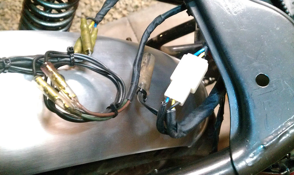
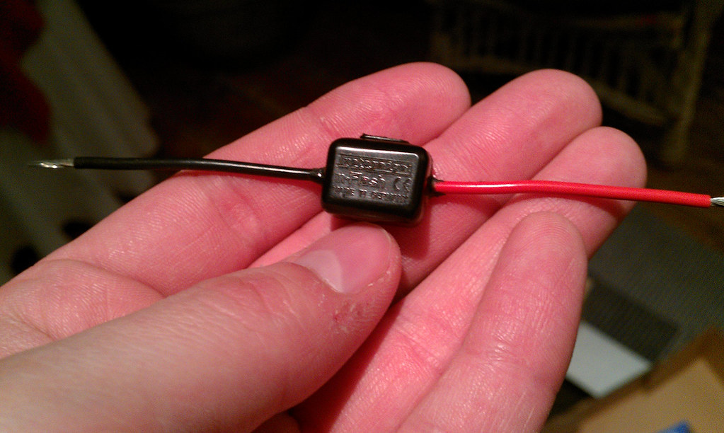
Nothing happened when the black wire touched the horn other than the horn beeped; the signal flashers are not part of this problem either. Speaking of the flashers: 23W bulbs should draw about 2A of current each, so you should have about 4A current flowing through the flasher unit (4A for each side but only one side works at a time).
Using your multimeter - you can check out if all the switch positions are making connections to the various wire circuits as shown in the wiring diagram (I'd start with the handlebar light switch first and the ignition switch second). Measure for continuity (0 ohms) between the plug wires as shown in the diagram. Also check to see that ONLY the wire circuits indicated on the diagram are connected together (no continuity where the switch position is not "made" between wires). If you do not find the problem and want to go further, you can unplug harness connectors and check for continuity across each wire color group but I don't think I'd advise it. Most electrical problems are in the areas of mechanical connections and switches (unless you discover cut wires, wire insulation rubbed "raw"/melted and shorting to other wire connections (or ground)) so I'd look there first. Disconnect bullet connectors, clean off the metal (brass brush, spray contact cleaner) and apply a light coating of grease or NoOx before reconnecting. If a switch is found defective, you might be able to disassemble it (carefully), clean it similar to bullet connections, and reassemble.
Nothing happened when the black wire touched the horn other than the horn beeped; the signal flashers are not part of this problem either. Speaking of the flashers: 23W bulbs should draw about 2A of current each, so you should have about 4A current flowing through the flasher unit (4A for each side but only one side works at a time).
")