
We noticed you are blocking ads. DO THE TON only works with community supporters. Most are active members of the site with small businesses. Please consider disabling your ad blocking tool and checking out the businesses that help keep our site up and free.
You are using an out of date browser. It may not display this or other websites correctly.
You should upgrade or use an alternative browser.
You should upgrade or use an alternative browser.
DIY Electronic Fuel Injection
- Thread starter Sonreir
- Start date
two-smoker
I reject your reality, and substitute my own!
This is a really cool topic. Signed on.
I got some connectors in the mail and finally hooked up the actual throttle bodies to the Arduino unit. I then wrote a quick program to record all the possible values while I actuated the throttle. I found the range of values coming back from the TPS to be between 158 and 834 (Arduino returns analog values on a 5V scale from 0 to 1023). Interestingly, the lower value, 158, occurs when the throttle is wide open and the higher values are recorded at the throttle closes.
I did a quick mapping to change the values into degrees of opening so that WOT is 90 and fully closed is 0. I then adjusted the idle to be open at just over 2°, but I might drop it back down to zero as it appears there are bypass air circuits built into the throttle body anyway. That's an implementation detail I'll worry about later, I suppose...
http://www.youtube.com/watch?v=hB6MDLh0PVo
teazer said:Matt, FYI, TPS is usually expressed in percent from zero to 100% . Mine maps out to 4.6 volts closed and 1.5v open. On teh street get as many map points as possible down in the first 25%
Thank you, sir. Good to know.
At the moment, it really helps to think of it as an angle. I'm doing a bit of trigonometry to calculate the effective open cross-sectional area of the throttle body as a function of the throttle plate angle. Once I know the effective area, I can use the MAP sensor to read the pressure drop and work backwards to CFM (which of course leads me to fueling).
As far as the programming is concerned, any linear range of numbers will do, but it's certainly good to think of it as a percentage as it might make some of the calculations a bit easier down the line.
eyhonda
Coast to Coast
Here is a 3D of the board I designed. I'm still working on the circuit. So, I haven't uploaded the Gerbers to make boards yet. I'm thinking if we commonize the circuit, we can share the PCB's. We get 3 to an order. Right now, I have it inside a 2x2 board ($20 at 4 sq in). With a smaller micro footprint, we can go even smaller.

I'll send a circuit as soon as I put in a few more changes. Let me know what micro you are planning to use. I know we kicked around a few options. I want the circuit to be as flexible as possible. Unused blocks can just be unpopulated or selected with jumbers (0 ohm). Also, this design is using old school axial components. We can go SMT if you want but old school is easier to build and fix. Or maybe, I'm just plain old school. Vintage parts on vintage bikes! Plus bigger parts are a bit more durable. I usually put ICs in sockets cuz I've been known to blow them up and removing them from a PCB is a PIA vs putting them in sockets. Ditto for the output transistors. I may also need to make space for a heatsink on the coil driver. Remember, we can also put the whole shebang on a circular board under the points cover if you plan to use a Hall Effect. I'm not there yet but it could be a version 2 or 3 down the road. Work in progress you know. Let me your thoughts on that.
I'll send a circuit as soon as I put in a few more changes. Let me know what micro you are planning to use. I know we kicked around a few options. I want the circuit to be as flexible as possible. Unused blocks can just be unpopulated or selected with jumbers (0 ohm). Also, this design is using old school axial components. We can go SMT if you want but old school is easier to build and fix. Or maybe, I'm just plain old school. Vintage parts on vintage bikes! Plus bigger parts are a bit more durable. I usually put ICs in sockets cuz I've been known to blow them up and removing them from a PCB is a PIA vs putting them in sockets. Ditto for the output transistors. I may also need to make space for a heatsink on the coil driver. Remember, we can also put the whole shebang on a circular board under the points cover if you plan to use a Hall Effect. I'm not there yet but it could be a version 2 or 3 down the road. Work in progress you know. Let me your thoughts on that.
eyhonda
Coast to Coast
Yes, it's the ignition module. I'll check that micro out.
[edit]
Whaddayaknow - same pinout! I'm using the ATMEGA168 plastic DIP.
basically the same but mine is half the memory:
ATmega168A 16KBytes 512Bytes 1KBytes 2 instruction words/vector
ATmega168PA 16KBytes 512Bytes 1KBytes 2 instruction words/vector
ATmega328 32KBytes 1KBytes 2KBytes 2 instruction words/vector
ATmega328P 32KBytes 1KBytes 2KBytes 2 instruction words/vector
That's awesome. I don't have to change micros or coding for us to coordinate the design.
getindachoppa
Been Around the Block
This sounds really interesting but in my opinion way to complicated with not to much gain out of it besides having a really cool fuel injection system on my bike.
It's an entertaining engineering exercise, but some performance gains are likely to be had. It's simply not possible to tune carbs as well as you can tune EFI. Furthermore, EFI throttle bodies are generally much less restrictive than carbs because they're not entirely dependent upon Bernoulli's principle for the introduction of fuel into the system.
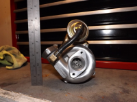
That said, the real gains will probably be had after I add this to the mix...
That said, the real gains will probably be had after I add this to the mix...
Attachments
two-smoker
I reject your reality, and substitute my own!
Touché!
getindachoppa
Been Around the Block
Sounds promising and exciting! I would like to see this on a bike application. When???
getindachoppa said:Sounds promising and exciting! I would like to see this on a bike application. When???
The EFI portion is likely to take me the next few months... currently investigating some options on how to get these throttle bodies to fit the head on my bike. I think I'm going to need to have some manifolds made.
I need to track down some wideband sensors, too.
getindachoppa
Been Around the Block
I have made manifolds before out of aluminum pipe and it is really easier than I thought it would be. Maybe I should do a post on how to do this.
eyhonda
Coast to Coast
I want to throw another feature into this mix, if you're game, Matt. I was just reading the new 899 Panigale review. How about an electronic quickshifter? With a microswitch on the shift pedal, we can delay either the fuel or ignition (don't know what's used) to allow clutchless shifts.


