540cc Honda 360 Engine

Exhaust valves are usually in the 80-85% range (area not diameter) because in theory, exhaust is under much higher pressure, so it can flow a whole lot more gas. In the real world, Mr. H had a habit of creating motors with intake ports that were way too larger and with the wrong geometry combined with exhausts that did not flow enough created a constipated motor.

Flow testing is a great investment and allows you to match the cam lift curve to the port flow characteristics.
 
cyclhed said:
Hi Rex, Thanks for finding my mistake, I listed the pistons as KZ1000, but Pops corrected me today and they are KZ1100 at 72.5mm diameter. Sorry for the confusion. I will correct my original post also. Please stay tuned and keep an eye on me!


So the Honda 350 & 360 have a 17 mm wrist pin?
I have used the CB450 pistons on a stock bore KZ1000 before.(70 mm)
Less expensive than Wiseco but not as durable,I crushed a ring land on one.
 
surffly said:
plan to dyno?

Not at the moment, but that would be great to be able to use a dyno to measure the increases. I suppose after he decides which head to go with, then the baseline should be measured before any port work is done. That's always an issue when doing stuff like this; you need a way to measure the improvements that you are hopefully making. Making the displacement larger is not the difficult part, relatively speaking. Improving the cylinder head breathing to take full advantage of the increase though requires a lot of effort.

I wonder how much effort and money would be needed to build a dyno to measure power? Rear wheel or engine type?
 
Sonreir said:
I agree that where empirical data exists, it should always but used. However, the use of flow benches and dynos for every engine modification can break that bank and so it's necessary to look at many problems and approach them with the knowledge gained from other applications.

For instance, it doesn't seem to be an unreasonable stretch of the imagination to make the assumption that today's head design is an improvement over the technology that was available 40 years ago. With that supposition in mind, we can make comparisons between today's technology and that of yesteryear.

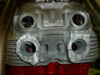
We now notice that port ceilings tend to be higher. Valve placements are a bit off center (to promote swirl). And also, exhaust ports tend to be larger (especially in hemi and tubbed heads).

Stock valve sizes for the CB360 are 34mm and 28mm for intake and exhaust, respectively. This gives us a sizing ratio of 82.3%.

Now looking at some more modern engines we can see the following:
Yamaha FJ1100 - 84%
BMW M5 - 86.3%
Cosworth F1 - 87.5%
Ducati 748R - 83.1%
Honda NS50 - 87.5%
Honda VF1100 - 88.1%

After going through a list of two pages of valve sizes, I was only able to find only a few cases of engines that use a smaller ratio than the Honda 350/360 and with the exception of one Harley, all of the others were purpose built race cars (not bikes).

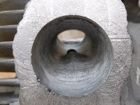
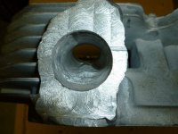
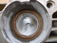
Even with the valve size ratio as it is, you will likely still see gains by reworking the exhaust port. I haven't checked recently, but there may be room to raise the ceilings a little and flatten the floors. The ideal shape would look like a 'D' laid on its flat side. Total exhaust port area should be at least 95% of the area valve, so you're looking for at least 858 square mm. If you do decide to hog out the exhaust ports, don't go crazy. You will want there to be a decent step between the exhaust port and the exhaust pipe as this helps to prevent reversion (especially in the low and mid RPM ranges).

Excellent, thank you for the research and food for thought Sonreir! Some effort is obviously required in this area for further development.
 
teazer said:
Exhaust valves are usually in the 80-85% range (area not diameter) because in theory, exhaust is under much higher pressure, so it can flow a whole lot more gas. In the real world, Mr. H had a habit of creating motors with intake ports that were way too larger and with the wrong geometry combined with exhausts that did not flow enough created a constipated motor.

Flow testing is a great investment and allows you to match the cam lift curve to the port flow characteristics.

Thank you for your comments teazer.
 
And 4 valve motors have more valve area relative to bore than 2 valve heads, but that's taking things to a whole other level. You can do the math. Aim for say 33% intake are:bore area and 82% exhaust area:intake area and work from there. Areas not diameters remember.

Increase stroke and you have more time for each valve event, so that's another variable. That motor has much longer stroke and will run at lower revs. It's not hard to take all of David Vizard or AG Bell's work and create a some simple spreadsheets to work out port geometry. Then get a lift curve for the cam and flow chart so that the head flows well at low lift but hits a flow wall at say 15% of valve diameter. Then the cam you want will be very different to one for a port that keeps on flowing well as lift increases.

That's why I like before and after flow charts for our heads and then I do cam lift curves and see which cam I need to make it all work. That gives a good starting point for development.
 
Nebr_Rex said:
So the Honda 350 & 360 have a 17 mm wrist pin?
I have used the CB450 pistons on a stock bore KZ1000 before.(70 mm)
Less expensive than Wiseco but not as durable,I crushed a ring land on one.

No, 350/360 is 15mm, we are using a 450/500 crank (and rods) which are 17 like KZ.
 
Pics of oil return fitting. Enjoy!

Pop's philosophy on this project:

"This is a (not so) simple "can this be done?" project, not a clean sheet
racing engine. I will use what I have, what is easy to get, and what
I can modify to make work. Nothing is written in stone and changes as
quickly as I think of better ways to do things, that for me is theoy
FUN part, and that's all this is about, me having fun. It is not my
intent to make the highest HP possible, just a decent running engine.
There are many way's to do things and I'm not interested in arguing
which is best. I'm happy to share the way I'm doing it. First hand
experience and info is always appreciated."
 

Attachments

  • P1000055s.JPG
    P1000055s.JPG
    94.6 KB · Views: 313
  • P1000054s.JPG
    P1000054s.JPG
    78.3 KB · Views: 319
cyclhed said:
No, 350/360 is 15mm, we are using a 450/500 crank (and rods) which are 17 like KZ.

Nice to know this for future reference.
15 is also the size for KZs 400,440 twins and 650/750 fours.
17 is for the 900/1000/1100s and 18 for the 83/84 GPZ1100
 
cyclhed said:
Pics of oil return fitting. Enjoy!

Pop's philosophy on this project:

"This is a (not so) simple "can this be done?" project, not a clean sheet
racing engine. I will use what I have, what is easy to get, and what
I can modify to make work. Nothing is written in stone and changes as
quickly as I think of better ways to do things, that for me is theoy
FUN part, and that's all this is about, me having fun. It is not my
intent to make the highest HP possible, just a decent running engine.
There are many way's to do things and I'm not interested in arguing
which is best. I'm happy to share the way I'm doing it. First hand
experience and info is always appreciated."

Agree 100%. Great to see so far.
 
Nebr_Rex said:
So the Honda 350 & 360 have a 17 mm wrist pin?
I have used the CB450 pistons on a stock bore KZ1000 before.(70 mm)
Less expensive than Wiseco but not as durable,I crushed a ring land on one.


15mm pin on 350 (and 250's) 16mm pin on 360.
Interesting modifications, love it. ;D 8)
Going to use stock stroke and 74mm pistons in 360 when I get too it, could probably go to 76mm if I find pistons with small pin, swap rods or something
Intake PORT is correct size for a 400cc motor, exhaust port has too much restriction particularly in bowl area and around guide boss.
Valve size is OK to 400cc, restricts top end a bit.
Thread bookmarked ;)

BTW, why the oil return?
 
Something I've been puzzling over since I saw pics, the 'return' line is tapped into main oil feed, you did a bunch of welding and cutting to do it.
Are you taking feed directly from pump on the right side, feeding to oil cooler/remote filter, cam then back into main gallery? (bypassing centrifugal filter)
 
crazypj said:
Something I've been puzzling over since I saw pics, the 'return' line is tapped into main oil feed, you did a bunch of welding and cutting to do it.
Are you taking feed directly from pump on the right side, feeding to oil cooler/remote filter, cam then back into main gallery? (bypassing centrifugal filter)

You can tell PJ that he is correct, oil out of the right side cover to filter/cooler then back to main gallery. Not sure if left side or right side will be inlet, other end of gallery will feed the head. Unneeded internal passages have been plugged. No welding required.
 
I have GOT to learn to weld aluminium 8)
Could you post some pics of welded up intakes?
 
Here's some pictures of head welding and ports to post. They are not finished yet, need to be cleaned up and carb mounting holes drilled and tapped, finish machine.
 

Attachments

  • P1000113.JPG
    P1000113.JPG
    167.1 KB · Views: 263
  • P1000112.JPG
    P1000112.JPG
    220 KB · Views: 286
  • P1000106.JPG
    P1000106.JPG
    206.7 KB · Views: 285
  • P1000104.JPG
    P1000104.JPG
    198.7 KB · Views: 294
Also some shots of mocked up frame I started. Mostly prototype so far to see if everything fits. Also need to make sure CB500T head fits in frame, as it is bigger.
 

Attachments

  • P1000105.JPG
    P1000105.JPG
    192 KB · Views: 289
  • P1000108.JPG
    P1000108.JPG
    215.8 KB · Views: 306
  • P1000111.JPG
    P1000111.JPG
    105 KB · Views: 297
Back
Top Bottom