1973 CB350G Canadian Noob Build (Gotta start somewhere!)

Saturdays Wrench said:
He took my starting clutch apart and inspected it thoroughly, noting that I would need to replace the rolling pins in the clutch. I inspected them myself and would suggest the replacement if you haven't in awhile. The pins can become warped causing the starting clutch to slip.

Worn roller pins can also cause the starting clutch to STICK. When that happens, you're riding along spinning the starting motor and severely wearing it out. I can hear in an instant if the clutch is stuck, but most people are unfamiliar with what sounds are usual for these bikes and wouldn't particularly pay it any mind. FYI, it sounds like a whirring sound, think of an electric drill being forced around by your engine. Unless you've been there before, again, it can be hard to make out.

Saturdays Wrench said:
Before that though he soaked the new cam chain in motor oil, said it was good practice. I like this guys style. He thoroughly cleaned off the grease that was on it when we took it out of the package. I can't remember what he called it but I think it was something like "packing grease" or something.. Maybe storing grease. I don't know but he wiped that crap off and we soaked the chain while we prepped the rest of the parts for the lower half of the engine.

Packing (or storing) grease doesn't make for a good lubricant. It is intended to be a rust preventative and does a fine job of displacing moisture. Problem is that most are composed of wax! Not easy to clean and not good for lubrication. Wax will not be dissolved by acetone/carb cleaner! You'll find that ordinary vegetable oil or mineral spirits works well. Put it into a tub-full and use a nylon brush to slough the wax off as it dissolves. Then soak the chain in the same type of motor oil you intend to run in the engine. This is the same process for new drive chains. Unfortunately, most are unaware and run them without cleaning. Even professional bike shops here will slap them on and send you out the door.

That crap smells like the cosmoline I used to get on the old WWII rifles I had. Serves its purpose but really must be removed.

On the subject of soaking parts in oil, you'll need to do the same for the friction plates of your clutch. Soak them for at least a few hours. Don't worry about the metal discs, it's the fibrous plates that need to soak the oil in to properly stick and cool.

Take a playing card, lick it, and stick it on your forehead. The wet clutch works in the same way. It won't stick to the plates if it ain't good and wet.

The black case looks mean as. Be prepared to hold your breath every time you crack a bolt off or test for fuel line leaks ;D
 
Redliner said:
On the subject of soaking parts in oil, you'll need to do the same for the friction plates of your clutch. Soak them for at least a few hours. Don't worry about the metal discs, it's the fibrous plates that need to soak the oil in to properly stick and cool.

Take a playing card, lick it, and stick it on your forehead. The wet clutch works in the same way. It won't stick to the plates if it ain't good and wet.

The black case looks mean as. Be prepared to hold your breath every time you crack a bolt off or test for fuel line leaks ;D

Ok thanks man, I was also unaware of the clutch friction plates needing a good soaking.

haha and ya, I hear you man. At least it'll look pretty for a little bit!
 
There is no way you are a WWII Vet, Vietnam yes.
By the way, Cosmoline is still made an that is great stuff for preserving metal parts for storage.
 
Habanero52 said:
There is no way you are a WWII Vet, Vietnam yes.

No bro, I literally beat up Hitler. I still live with that regret every day. He was a pretty güd guy.

Obviously it would be impossible for me to have owned surplus military rifles if this were not true.
 

Attachments

  • compassion-for-animals-quotes-3.jpg
    compassion-for-animals-quotes-3.jpg
    47.1 KB · Views: 1,102
  • chuchill lied.jpg
    chuchill lied.jpg
    101.8 KB · Views: 1,149
Well, I just spent, no, invested an hour to read through your thread and I have to say I'm impressed. At first I thought you'd be like some who have big dreams and very little ambition. You've proved you have staying power and determination to see your project through, well done young man.

Video/editing appear to be pro standard, are you involved in the media in some way?

I'm very much looking forward to seeing the bike come together and will be checking in regularly from now on.

Makes my project seem like a weekender's dicking about haha!

Best wishes from Old Blighty - Colin
 
Some very nice work rebuilding those cases, the transmission, etc. I wish I was able to split and rebuild cases that well. Build is looking good.
 
Redliner said:
No bro, I literally beat up Hitler. I still live with that regret every day. He was a pretty güd guy.

Obviously it would be impossible for me to have owned surplus military rifles if this were not true.

lol
 
NoRiders said:
Well, I just spent, no, invested an hour to read through your thread and I have to say I'm impressed. At first I thought you'd be like some who have big dreams and very little ambition. You've proved you have staying power and determination to see your project through, well done young man.

Video/editing appear to be pro standard, are you involved in the media in some way?

I'm very much looking forward to seeing the bike come together and will be checking in regularly from now on.

Makes my project seem like a weekender's dicking about haha!

Best wishes from Old Blighty - Colin

Thank you for the kinds words. I really appreciate that. This has probably been one of the most challenging and time consuming things I have done in my life and now that I am finally seeing it come together it feels incredible. I will probably tear up when I start the bike up for the first time haha.. Yes I work in the post production industry as a motion graphics designer with a strong background in shooting/editing.

Anyway thanks again Colin and good luck with your project too man!

Luugo86 said:
Some very nice work rebuilding those cases, the transmission, etc. I wish I was able to split and rebuild cases that well. Build is looking good.

Thanks but I owe it all to Jeff Busche, the mechanic who is helping/guiding me through the rebuild. He would not accept anything else but 100% clean! Anyway thanks for the sentiment!
 
Happy Holidays everyone!

Here's the 1st video from a 3 part series of my engine rebuild. There is a lot of excellent info in this one! This is an insightful video and I recommend you watching it if you're thinking of just slapping your engine together. A lot of stuff needs to be inspected and this insightful guide will shed some light on what you need to look for. Obviously common sense to some but not for us rookies. Hope you like it!

https://youtu.be/CKbLNdc_f0I

I'll should be back soon with the bottom end video. We are awaiting on some gaskets to come in from Bore Tech, but since it's the holidays the packages are taking their sweet time!!

Until next time! Happy New Year guys!!
 
Hey guys, just a quick update!

The bottom end is finally assembled and finished. It is looking sweet!! Super clean and ready to roll. I was really excited to see it come together and after watching the mechanic I'm confident I could do another one myself, no problem.

Here is the video of the bottom end assembly:
https://youtu.be/Gme9yClDPJU


The top end is coming along.. slowly but surely. We ran into a number of walls with it but it is to be expected when doing a full engine rebuild. I did not have the proper head gasket for my big bore piston size and was under the impression that it would've come with the gasket kit I purchased at the time when I purchased the big bore piston. So if you ever buy the big bore kit, make sure you buy a larger head gasket that will fit the larger sized pistons. Probably common sense for more experienced builders, but completely went over my head. Once you change one component in the engine it will effect all the other components down the line.

We are at the stage where we have dry assembled the top end completely. We basically mocked up the assembly without the piston rings on the pistons and light weight springs on the valves. We left those components out so that we could turn the engine over easily, allowing us to measure our clearances. I will get into details more when I post the video for that but not for a few weeks since it's not finished yet. I am heading back this Saturday to wrap everything up and then will get to work on editing the video.

I am also planning on building the forks and installing everything into the swing arm so that is all ready to put together. I picked up my wheels from the wheel builder over the holidays and they are all trued up and balanced with the sweet new Avon AM26 rubbers installed.. Looking so damn nice!! Can't wait to show you guys. After the engine is finished up I am hoping to get everything together pretty quickly. I've been hording parts the last month in anticipation for the engine completion and have a good stock pile to get me pretty far in the next few months! I am giving myself a mid March deadline to finish, so the hustle is on!!

I'll be back with the next video and an update soon!
 
IT'S UPDATE O'CLOCK

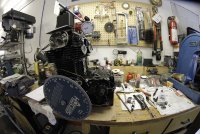
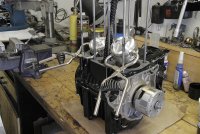
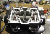
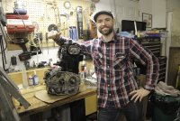
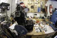
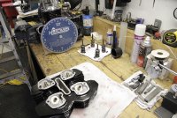
So I can finally sleep at night.. The engine is buttoned up!! Exciting times friends. We finally finished up last weekend and all I have to do now is install the clutch, oil pump and filter and other small items. Rebuilding this engine was quite the process. It took a lot longer than I thought it would as it was a bit distracting having the cameras around and trying to film and explain as we went along. Either way it's done and I have learned a lot in the process! These engines are truly fascinating and I can confidently say I am fully familiar with how the whole thing works and every little part that contributes to its function. It makes me feel good that I will know how to repair or fix any problems that may arise in the future, but hopefully it won't come to that.

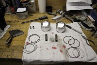
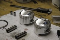
So enjoy a write up and some pictures for now, I should have the video up in the next few weeks! Keep in mind that the process your about to read was particular to my personal situation because I have over sized pistons (67.5mm BoreTech Big Bore Pistons), a cam shaft with larger lobes (#12320-RG Cam) and upgraded Kibblewhite valves and springs.

I'll try to quickly explain what we did and why things took longer than expected as best I can. Firstly, during assembly we figured out that I did not have the correct head gasket. That's a pretty big wall to hit. I had to order one and it took nearly 3 damn weeks to arrive due to the amount of packages the flood the post office over the holidays. While awaiting that, we discovered that a few other parts inside the engine were worn and needed to be replaced. This included the o-rings for the rocker arm pins, the rubber cam chain guide and the 2 little rubber pieces that hold the cam chain tensioner in place at the base of the cylinders.

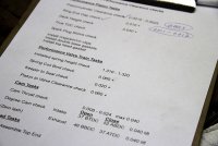
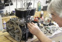
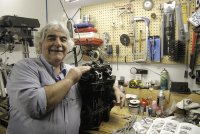
After that hiccup we were off to the races! Jeff Busche, the mechanic that helped me with the rebuild noted that we needed to "dry assemble" the engine in order to complete a list of tasks that needed to be preformed to ensure the engine would operate safely and not blow up as soon as I hit the start button. These tasks included many clearance checks to make sure all of the performance parts would play nicely with each other. It also meant that we would assemble the whole top end without the piston rings and heavy duty valve springs. Without these components, the engine turns over with ease making our work a lot easier. The documentation that came with the high performance parts also indicated and warned us to complete these checks. I can guess that some of you will tell me that we wasted our time or that some of these tasks were unnecessary for everyday riding but as a licensed mechanic, Jeff has a reputation to uphold and it's my money and safety on the line, so I was more than happy to go through the process.


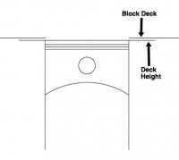
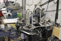
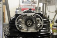
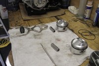
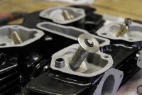
The 1st check we needed to complete was the deck height or piston to head clearance. This is the top of the squish band on the piston to the deck of the cylinder head:


WTF is piston deck height & why does it even matter?! "Piston deck height is a VERY important measurement to consider when designing a combustion chamber. Piston deck height is a major player in determining the squish clearance of an engine. The squish action within a combustion chamber is very important in the combustion process and power making process. Squish clearance is the distance from the edge of the piston, at TDC, to the outer edge of the combustion chamber's squish band. So, one can easily see how the piston deck height effects the squish clearance measurement." Read more here: http://www.2strokeheads.com/tech1.htm

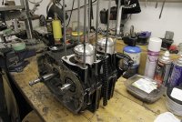
Our minimum recommend clearance was 0.030" and with the base gasket I had, we only had about 0.015”. Our solution was to double up the base gaskets to raise the jugs up, effectively gaining more space between the top of the piston and cylinder deck. After all was said and done we achieved approximately 0.035" of deck height, slightly higher than our recommendation. This satisfied both of us and after some deliberation we decided to move on.

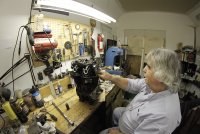
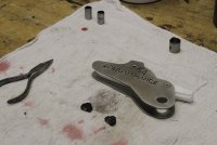
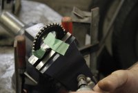
We realized that the cam shaft would not fit into the stock cam sprocket so Jeff took the dremel to the inner cam sprocket window and removed a tiny amount of material so that there was JUST enough clearance to fit the larger lobes through. We practised putting the cam through the sprocket a bunch of times outside of the engine but still had a HECK of a time with it once we got to the point when we needed to install it into the cam box. It seriously took us about 30 minutes or so.. it was stressful but funny. All I can recommend to you is to be as patient as possible. Once we DID get the cam to slide through the sprocket we struggled to fit the side covers onto the cam box like CRAZY! The new cam chain and tensioner were super tight and theres barely any room but we did it eventually. We didn’t torque the top bolts with stacks of washers but did tighten them quite significantly. We probably struggled with this for an hour at least! Jeff used this “lady foot” pry bar to help him lift the cam upwards as we slipped the tach cover on.. it was nuts! I honestly didn’t think it was going to work out and I was scouring the internet for solutions. Found a bunch on here and emailed/called a few experienced 350 builders for advice too! Thanks guys. Either way we did not have to shave any rubber off the sprocket. Once we did get the cam and side tach/points covers in place we rotated the engine a bunch to get the chain to work itself into place and get familiar with everything so that when we did the final assembly it would be easier.

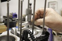
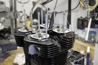
We disassembled my cylinder head and replaced the heavy duty valve springs with light weight springs. The reason for this was to be able to easily measure valve to piston clearance and proper cam to crankshaft relationship. The light weight springs allow easy movement in the valves, yet hold them in the closed position as they normally function during engine operation. Now I FULLY realize that most people simply stick some clay or solder onto the valve pocket in the piston and rotate the engine forcing the valve to squish the material onto the piston head and measure that, but Jeff had his method and who was I to argue. Jeff replaced the springs and we installed the head and measured that when any piston and any valve were at a point when they were the closest they would ever be together inside the engine, they had at least 0.035" to go before they would connect with each other. Basically we rotated the engine and watched the piston and valve through the spark plug hole, when the 2 were at a point in the engine rotation where they were the closest they would ever be to each other we took our measurement from there. Hopefully that is making sense to those who've never done this before. We mounted a dial gauge to the top of the engine and measured from the valve steam head and pushed down until it touched the top of the piston. This was approx 0.095” of travel and our minimum clearance was 0.060". Another successful task completed.

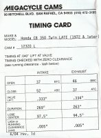
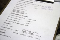
Next we needed to ensure that the relationship between the cam shaft and the crankshaft was correct. On the task list that Jeff wrote out he described this as “Degree cam check”. I will try my best to explain it as I understand it but basically when the crankshaft is at a certain degree of rotation the camshaft should be pushing the valves open or closing them to a specific distance. They provide the distance on the timing card that comes with the camshaft. Here is what mine looks like:


As one example, It states that at exactly 0.040” of lift for the intake valve the crankshaft should be 37 degrees BEFORE top dead center (BTDC). To read exact degrees of rotation we attached a degree wheel onto the end of the crankshaft and set it so that 0 degrees marked top dead centre (TDC) for the left cylinder of the compression stroke. How we did this was by screwing a special stopper into the spark plug hole. It was a long piece of black metal that came to a rounded point and how it works is that you rotate the crankshaft so that the piston is coming up to TDC, then screw in your stopper and continue to rotate the crankshaft slowly until the piston comes up and makes contact with the stopper and stops. Set your degree wheel at something like 30 degrees BEFORE top dead center and fix it to the crankshaft so it moves simultaneously . We also fixed a piece of copper wire onto the engine and used it as a pointer so we could accurately read the degrees. Now, with the degree wheel fixed to the crankshaft, remove the stopper and continue to rotate the crankshaft in the same direction as before so that the piston comes to up to TDC and then continues downward in the cylinder. You will notice that the degree wheel will show that the degrees are counting down towards zero then move past zero and start to count up again, indicating the piston has passed TDC. Once the piston is sufficiently out of the way, put the stopper back in and carefully rotate the crankshaft in the reverse direction this time (back towards 0 on the degree wheel), so that the piston moves back upwards in the cylinder towards TDC and bumps into the stopper. Look at the degree wheel and notice that it will be close to 30 degrees AFTER top dead center (ATDC). What you are looking for is an EXACT number on either side of the ZERO mark on the degree wheel for when the piston bumps into the stopper. I’m using 30 degrees as a jumping off point but in my particular case it was 33.5 degrees on either side exactly. It’s hard to explain without a visual and I hope to make an animation in my next video but the EXACT middle of the 2 values is 0 degrees and that is how you know EXACTLY that your piston is at TDC and your readings are correct as long as your degree wheel doesn’t slip. Once the degree wheel was set up we could find 37 degrees BTDC easily. We moved the crankshaft until the intake valve on cylinder #1 was closed and attached our dial gauge to the top of the valve stem. As we approached 37 degrees BTDC the valve started opening & sure enough when the crankshaft was approximately at 37 degrees BTDC the valve was open 0.040”. It may have been a degree off but we were both pretty satisfied and attested the minuscule discrepancy to human error or set up errors and decided to move on. 1 degree is not the end of the world.


Hopefully you’re still with me here, I’m doing my best to keep it quick while explaining my experience so that it makes sense. We did this check for each valve & also did a valve keeper to seal check and a spring coil bind check to make sure that the camshaft didn’t bind the spring coils before it finished it’s full rotation. We checked end gap for all piston rings and finally the piston to cylinder clearance. All good in the hood! Thorough! We finished ALL these checks, dismantled the top end and began the final assembly.

You can see now why it took us longer than we thought, but I am glad we completed all these checks. We struggled a bunch with getting the piston rings into the cylinders and with sliding the camshaft through the sprocket for some reason. No matter how many times we practiced, it still would slide together easily! The points/tach cover went on a lot easier this time and once we properly lubed everything up and rotated the engine a complete turn to do one last final check we buttoned up the top and torqued everything into place!!

Let me tell you that a huge weight feels like it has been lifted from my shoulders. The engine rebuild seemed like a mountain of a task for me but after watching Jeff work I can confidently say that I could definitely build one myself next time and just may do that for practice and to have a spare on hand. It was really a lot of fun working with Jeff at Busche’s Garage and I learned a lot from the experience. Moving forward I will adopt his techniques and hopefully become better at this stuff.. I already feel like I’m a lot more organized in my approach to the build.

I am looking forward to finishing the engine up and installing everything on the sides and getting it mounted into the frame. I will hopefully be doing that soon and getting started on building up the frame from there! Pretty excited about everything.. Spring is coming! Back to the grind!!

Sorry for the novel & I apologize in advance if I made an errors with explaining this stuff. 8)
 

Attachments

  • _MG_7379.JPG
    _MG_7379.JPG
    548.8 KB · Views: 299
  • Megacycle Cam timing card 12320L.jpg
    Megacycle Cam timing card 12320L.jpg
    130.7 KB · Views: 1,379
  • p110977_image_large.jpg
    p110977_image_large.jpg
    8.5 KB · Views: 1,403
  • _MG_7234.JPG
    _MG_7234.JPG
    433.4 KB · Views: 296
Great job and excellent detailed coverage! And for my money's worth, the time invested in all of those pre-checks will pay back at least 10-fold in time spent riding trouble free with that new powerplant humming away between your legs. Errmmm.... :eek:

Looking forward to the vid.

Cheers!
Kirk
 
I only have this tip based on what I read: do not install the cam chain tensioner until the camshaft is installed and indexed properly...
 
speedmotoco said:
Nice job!
Redliner said:
I only have this tip based on what I read: do not install the cam chain tensioner until the camshaft is installed and indexed properly...
Kcomrie71 said:
Great job and excellent detailed coverage! And for my money's worth, the time invested in all of those pre-checks will pay back at least 10-fold in time spent riding trouble free with that new powerplant humming away between your legs. Errmmm.... :eek:

Looking forward to the vid.

Cheers!
Kirk

Thanks guys! :)
 
I finally finished up the video and posted it this afternoon. I hope those of you who are just learning this stuff like me can get something out of the video.. well I'm sure you will actually. It's a lot longer than my usual stuff but it was a 30+ hr process with checking clearances, running into walls and assembling 2 times.

Either way I hope you enjoy the process video and some pics:
https://www.youtube.com/watch?v=IkQ1KZlf3DM
 

Attachments

  • _MG_7465.jpg
    _MG_7465.jpg
    258 KB · Views: 297
  • _MG_7490.jpg
    _MG_7490.jpg
    274.3 KB · Views: 293
  • _MG_7504.jpg
    _MG_7504.jpg
    275.1 KB · Views: 290
  • _MG_7536.jpg
    _MG_7536.jpg
    224.5 KB · Views: 316
  • _MG_7607.jpg
    _MG_7607.jpg
    242.6 KB · Views: 291
  • _MG_7597.jpg
    _MG_7597.jpg
    189.2 KB · Views: 287
  • _MG_7639.jpg
    _MG_7639.jpg
    285.6 KB · Views: 291
  • _MG_7647.jpg
    _MG_7647.jpg
    292.6 KB · Views: 307
  • _MG_7649.jpg
    _MG_7649.jpg
    289.8 KB · Views: 288
  • _MG_7653.jpg
    _MG_7653.jpg
    285 KB · Views: 290
  • _MG_7657.jpg
    _MG_7657.jpg
    257.7 KB · Views: 306
  • _MG_7415.jpg
    _MG_7415.jpg
    241.3 KB · Views: 283
  • _MG_7378.jpg
    _MG_7378.jpg
    294 KB · Views: 294
  • _MG_6900.jpg
    _MG_6900.jpg
    271.4 KB · Views: 283
  • _MG_6904.jpg
    _MG_6904.jpg
    216.9 KB · Views: 270
  • _MG_6979.jpg
    _MG_6979.jpg
    280.2 KB · Views: 293
  • _MG_6982.jpg
    _MG_6982.jpg
    216.7 KB · Views: 290
  • _MG_7009.jpg
    _MG_7009.jpg
    188.4 KB · Views: 281
  • _MG_7234.jpg
    _MG_7234.jpg
    215.7 KB · Views: 289
  • _MG_7243.jpg
    _MG_7243.jpg
    289.9 KB · Views: 288
  • _MG_7263.jpg
    _MG_7263.jpg
    293.5 KB · Views: 281
  • _MG_7269.jpg
    _MG_7269.jpg
    166.7 KB · Views: 289
  • _MG_7294.jpg
    _MG_7294.jpg
    217.2 KB · Views: 279
  • _MG_7333.jpg
    _MG_7333.jpg
    157.1 KB · Views: 307
  • _MG_7676.jpg
    _MG_7676.jpg
    263.2 KB · Views: 292
Back
Top Bottom