We noticed you are blocking ads. DO THE TON only works with community supporters. Most are active members of the site with small businesses. Please consider disabling your ad blocking tool and checking out the businesses that help keep our site up and free.
You are using an out of date browser. It may not display this or other websites correctly.
You should upgrade or use an alternative browser.
You should upgrade or use an alternative browser.
1976 Puch Maxi - APuchalypse Now
- Thread starter Sonreir
- Start date
Will there be a mount for a crossbow?
Sent from my VS985 4G using Tapatalk
Sent from my VS985 4G using Tapatalk
canyoncarver said:Will there be a mount for a crossbow?
Sent from my VS985 4G using Tapatalk
Seriously debating it.

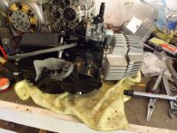
More work done today.
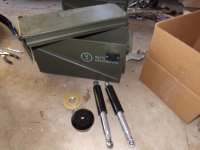
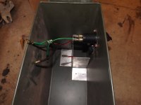
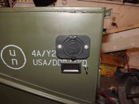
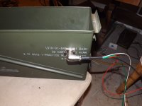
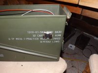
Started prepping the ammo can to use as a panier and electrical box. I have another but I'm still deciding if I want to use both. I'm toying with the idea of putting a jerry can on the opposite side.
Got some paint on the suspension uppers, freewheel, and speedo housing. Plastidip on the fork lowers.
Attachments
iatethepeach
Coast to Coast
Ha ha. Cool panniers. What voltage is the bike, and are you using a buck converter for your USB charger? I dig the DRO.
stroker crazy
crazy as a fox
Sonreir said:a Puch Maxi for an extra $6 … Not going to go too crazy on this one …
Sonreir said:Guess I'll have to buy a mill.
There's nothing quite like a cheap build to empty the wallet!
Crazy
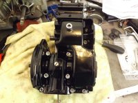
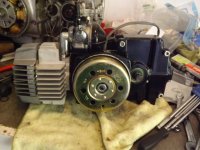
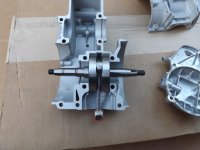
More parts arrived today and I got my cases back from the machinist (I had them cleaned and bead blasted).
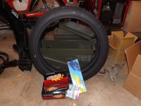
New tires, tubes, chains, crankshafts, and a CDI stator.
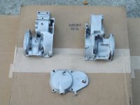
I tested fitted the new crank that arrived and then laid down some color on the cases.
New crank has a roller bearing in the small end, which is both nice and unexpected.
New tires, tubes, chains, crankshafts, and a CDI stator.
I tested fitted the new crank that arrived and then laid down some color on the cases.
New crank has a roller bearing in the small end, which is both nice and unexpected.
Attachments
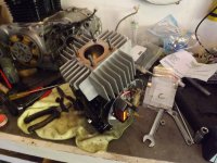
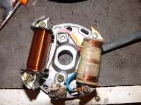
Getting the CDI stator and rotor in was a real treat because I finally got to see if this thing would be convertible to DC.
And it can be.
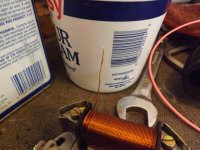
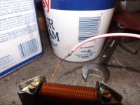
First step was the float the ground on the lighting coil. In an AC setup, one end of the coil is grounded while the other is the wire that leads out of the stator. To convert to DC, we need to unground the unwired end of the coil and then use a multimeter to verify that the coil wires are no longer grounded.
After confirmation, we can solder another wire onto the now ungrounded section of the coil wire. The solder is not likely to look good because of the enamel coating on the wire prevents good contact in some places. After the solder job is complete, insulate the connection to prevent it from grounding out again. Break out the multimeter and test again. Ensure the coil remains ungrounded and that you have a low resistance value between your two stator wires.
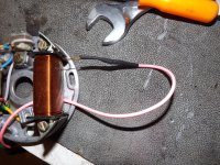
If everything checks out, route the new wire out of the stator along with the others and then perform one final check to ensure no continuity to ground and that the circuit between the two ends of the coil is complete.
The two wires can now be run to a single phase rectifier (and regulator, if desired) and the bike is now DC instead of AC.
My other coil remains AC to power the CDI system, which requires it.
And it can be.
First step was the float the ground on the lighting coil. In an AC setup, one end of the coil is grounded while the other is the wire that leads out of the stator. To convert to DC, we need to unground the unwired end of the coil and then use a multimeter to verify that the coil wires are no longer grounded.
After confirmation, we can solder another wire onto the now ungrounded section of the coil wire. The solder is not likely to look good because of the enamel coating on the wire prevents good contact in some places. After the solder job is complete, insulate the connection to prevent it from grounding out again. Break out the multimeter and test again. Ensure the coil remains ungrounded and that you have a low resistance value between your two stator wires.
If everything checks out, route the new wire out of the stator along with the others and then perform one final check to ensure no continuity to ground and that the circuit between the two ends of the coil is complete.
The two wires can now be run to a single phase rectifier (and regulator, if desired) and the bike is now DC instead of AC.
My other coil remains AC to power the CDI system, which requires it.
Attachments
OK. Back from a business trip in Seattle and came back to a truck load of new parts to play with.
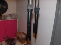
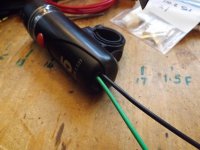
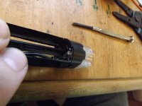
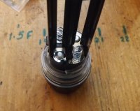
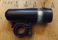
I decided to start with the bicycle lights I ordered.
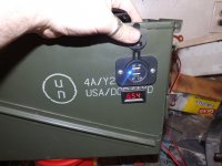
When I bought them, I saw that they used 4 AA batteries. Batteries are generally 1.5V each, so 1.5 x 4 = 6V. What I was hoping is that the four batteries were arranged in series and not parallel. If they were setup in parallel then it would be a 3V system with twice as much battery life.
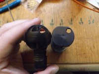
I was in luck. By looking at the power plates up against the light, we can see that the positive and negative plates on one side are the same piece of metal and so the circuit is definitely in series.
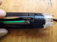
My drill press was employed to drill a hole through the back of the the each light assembly and pulled out all of the redundant battery plates.
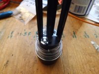
A bit of soldering to hardwire them and everything fits together quite nicely again.
I now have two 6V bicycle lights that will run off of the bike's power.
I decided to start with the bicycle lights I ordered.
When I bought them, I saw that they used 4 AA batteries. Batteries are generally 1.5V each, so 1.5 x 4 = 6V. What I was hoping is that the four batteries were arranged in series and not parallel. If they were setup in parallel then it would be a 3V system with twice as much battery life.
I was in luck. By looking at the power plates up against the light, we can see that the positive and negative plates on one side are the same piece of metal and so the circuit is definitely in series.
My drill press was employed to drill a hole through the back of the the each light assembly and pulled out all of the redundant battery plates.
A bit of soldering to hardwire them and everything fits together quite nicely again.
I now have two 6V bicycle lights that will run off of the bike's power.
Attachments
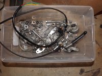
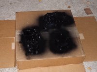
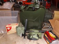
Attached is a pic of some of the items I got in.
Jerry can, trench tool (has saw, spade, and hatches), first aid kit, "survival" shovel, 4-in-1 hatchet and pry bar, and a canteen.
I also started the wiring for the pannier to the rest of the bike. I've enlisted the help of a three pin XLR microphone jack so that the pannier can be disconnected from the rest of the bike.
Attachments
JustinLonghorn
No Purple Hearts, No Blue Ribbons
It still needs a crossbow mount.
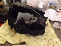
I got the crank back from the machinist (had new bearings pressed on) and so it was time for everything on the engine to go back together.
I'm loving how simple this thing is. No valves and only one gear.
I'm loving how simple this thing is. No valves and only one gear.