
We noticed you are blocking ads. DO THE TON only works with community supporters. Most are active members of the site with small businesses. Please consider disabling your ad blocking tool and checking out the businesses that help keep our site up and free.
You are using an out of date browser. It may not display this or other websites correctly.
You should upgrade or use an alternative browser.
You should upgrade or use an alternative browser.
'82 Moto Guzzi v50 Rebuild/Redesign
- Thread starter zachattach
- Start date
zachattach
Project Doldrums
So, the project has a new home. While it may only be a temporary one, it's time to role up my sleeves and get to work.
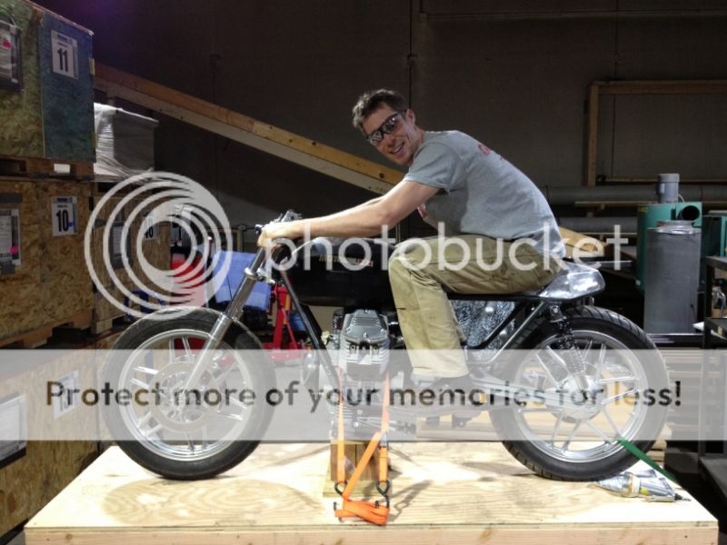
I am loving the look with the clip-on bars, and they are here to stay. These bars dramatically change the riding position, however, and it is going to necessitate changing the position of the foot pegs and foot controls to allow you to drop down into an aggressive riding position. While my frame and monkey arms wrapped around this little bike are going to make any and every riding position look awkward, here I sitting knees to chest demonstrating the stock position:
My idea is to bring the foot pegs and foot controls as far back as possible, and fortunately, the shift linkage will work ever bit as well with the throw arm actuated by the foot lever simply flipped around 180 degrees. It should make this mod relatively straightforward instead of the nightmare I was anticipating. Repositioning the foot operated brake control should be even easier since it is now cable driven.
Here is where I think I can push the controls and peg back to:
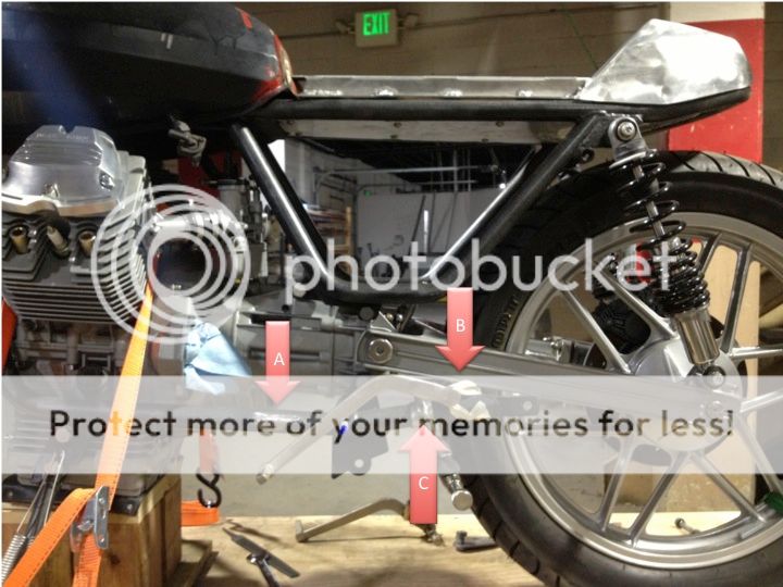
Arrow A = the original foot peg location
Arrow B = the new pivot point for the foot shift control (could possibly go below frame rail too)
Arrow C = the locking pliers that clipped on to try out the new foot peg position
The result is a lot more comfortable with the new bars, and with a smaller-framed rider on the bike the modified position looks great (unfortunately I don't have a pic).
Committed to the mod, I chopped off the old foot pegs and their brackets and cut out the pivots for the foot controls. The holes the latter left in the lower frame rails certainly left me second guessing myself:
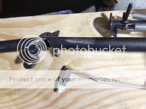
Once I am done filling them, though, you'll never notice. It is just going to result in a lot of work. I suspect this is also going to result in a lot of custom exhaust work too.
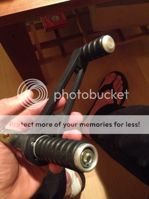
If any one has any recs regarding new, good-looking foot pegs to replace the old clunk rubber ones with I am all ears, especially if I can buy the appropriate frame brackets for them. Something clean, aluminum, and unpretentious would be nice.
Happy to be at it again!
I am loving the look with the clip-on bars, and they are here to stay. These bars dramatically change the riding position, however, and it is going to necessitate changing the position of the foot pegs and foot controls to allow you to drop down into an aggressive riding position. While my frame and monkey arms wrapped around this little bike are going to make any and every riding position look awkward, here I sitting knees to chest demonstrating the stock position:
My idea is to bring the foot pegs and foot controls as far back as possible, and fortunately, the shift linkage will work ever bit as well with the throw arm actuated by the foot lever simply flipped around 180 degrees. It should make this mod relatively straightforward instead of the nightmare I was anticipating. Repositioning the foot operated brake control should be even easier since it is now cable driven.
Here is where I think I can push the controls and peg back to:
Arrow A = the original foot peg location
Arrow B = the new pivot point for the foot shift control (could possibly go below frame rail too)
Arrow C = the locking pliers that clipped on to try out the new foot peg position
The result is a lot more comfortable with the new bars, and with a smaller-framed rider on the bike the modified position looks great (unfortunately I don't have a pic).
Committed to the mod, I chopped off the old foot pegs and their brackets and cut out the pivots for the foot controls. The holes the latter left in the lower frame rails certainly left me second guessing myself:
Once I am done filling them, though, you'll never notice. It is just going to result in a lot of work. I suspect this is also going to result in a lot of custom exhaust work too.
If any one has any recs regarding new, good-looking foot pegs to replace the old clunk rubber ones with I am all ears, especially if I can buy the appropriate frame brackets for them. Something clean, aluminum, and unpretentious would be nice.
Happy to be at it again!
50gary
Under the Limelight
Perhaps you could have removed the original foot pegs by only grinding off the welds and not cutting into the frame tube? A small angle grinder can do some nice work if you're patient. I also use a chisel and big hammer to remove some tabs and brackets. Mild steel is easy to cut. Just a thought for next time. Your bike is going to be great when finished. Guzzi are a special brand for me and those wheels are very nice.
Cheers, 50gary
Cheers, 50gary


zachattach
Project Doldrums
Hey Remfanuk (Nigel?)
Those are some pretty sharp looking rear sets. A few weeks ago I stumbled upon Tarozzi and their rear sets. Recently picked up a pair and the originals are not an after thought.
Regarding coating the Brembo's: I opened them up, removed all plastic pieces, did some careful masking so as not to disturb precision machined elements, and then sand blasted them. The original finish came off quite easily. With that stripped I then powder coated them. Did the same for the rear master. If you specifically like the color or finish on them LMK and I will get the exact name of the powder I used.
zachattach
Project Doldrums
*and the originals are not going back on.
zachattach
Project Doldrums
This is all a bit of old news, but this week is going to be a busy one for the project. Might as well get caught up.
So, discovered and then bought a pair of these babies:
And the well the Tarozzi's have simplified a great many things for me, they have also made this painstaking work unnecessary:
and the final product (on one side)
As you'll see in the last photo the right left frame rail is now patched. The right is still open. Unfortunately, with my plans for how I am going to set up the Tarozzi's I will need the left side back open in the exact same spot I just patched, and the right side still needs to be patched.
If the tubing and bearing I ordered to set up the shifting linkage on the left side arrives today I will be boring the left frame rail back out today and getting the right side patched up in the same manner depicted here.
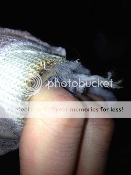
One more fun detail. In one of the pictures above you will notice what looks like a cast on my hand. It is. I did this while skiing some gnarly chutes in the Steamboat Springs, CO back country this winter:

While I was grinding down the above frame rail patch the sparks got into the cotton liner of the cast and caused it to briefly catch fire. Whoops...
So, discovered and then bought a pair of these babies:
And the well the Tarozzi's have simplified a great many things for me, they have also made this painstaking work unnecessary:
and the final product (on one side)
As you'll see in the last photo the right left frame rail is now patched. The right is still open. Unfortunately, with my plans for how I am going to set up the Tarozzi's I will need the left side back open in the exact same spot I just patched, and the right side still needs to be patched.
If the tubing and bearing I ordered to set up the shifting linkage on the left side arrives today I will be boring the left frame rail back out today and getting the right side patched up in the same manner depicted here.
One more fun detail. In one of the pictures above you will notice what looks like a cast on my hand. It is. I did this while skiing some gnarly chutes in the Steamboat Springs, CO back country this winter:
While I was grinding down the above frame rail patch the sparks got into the cotton liner of the cast and caused it to briefly catch fire. Whoops...
zachattach
Project Doldrums
So, the follow on from hell week. I put 50 or 60 hrs into the project a few weeks back to take advantage of the last week of shop access I had. During the week my projects were as follows:
-rear set shift linkage bearing assembly
-rear master brake cylinder re-relocation mounts
-rear set lower frame rail mounts.
Rear shift linkage fab:
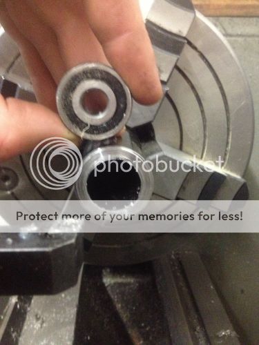
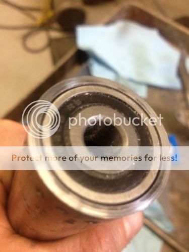
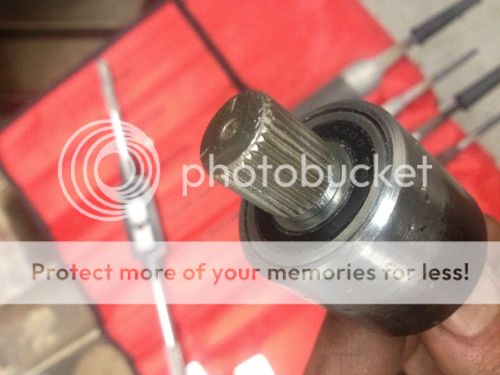
1. I ordered a number of different bearings before finding the right one for my rear shift linkage plan. The one I identified has an OD of 25mm, and ID of 10mm, and has internal two ball bearing races that provide great lateral stability. The marker points at the winner.
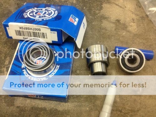
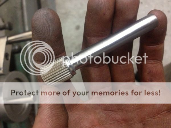
2. With this identified. I ordered up some chrome alloy tubing (due to the structural significance) to machine the bearing journal from. Here is the machining process. Chrome Alloy machines beautifully btw, provided you have carbide tooling to work with.
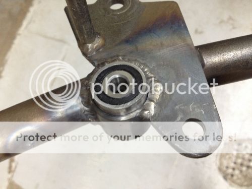
3. I then re-cut a recess out of the lower frame rail for the bearing assembly
4. And welded the assembly in.
5. Following this I separated the press fit on the original shift foot control.
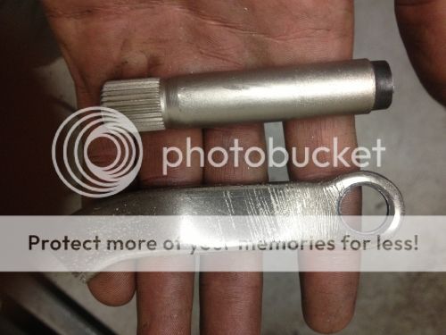
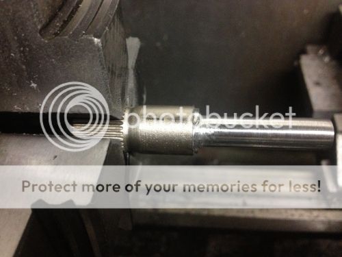
6. and machined down the spindle to be compatible with my bearing's ID. This was slightly disconcerting.
7. End Result (kind of)
Rear Master Cylinder Re-Relocation:
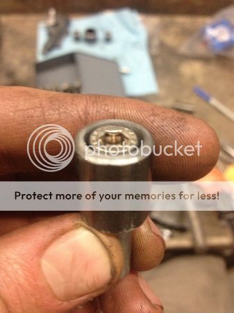
1. Bungs fabed from mild steel solid bar stock (center four objects)
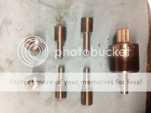
2. The bungs recess the bolts such that they will provide a very clean finished look that matches the lower frame rail joint design.
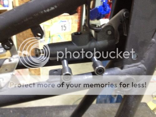
3.Approximate new location
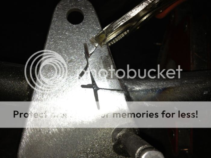
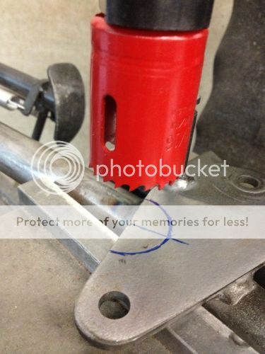
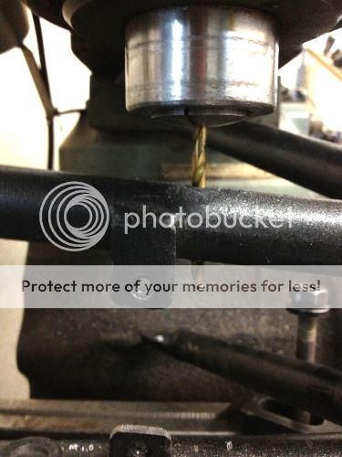
4. To ensure everything was properly aligned I used a mill to drill the holes in the frame:
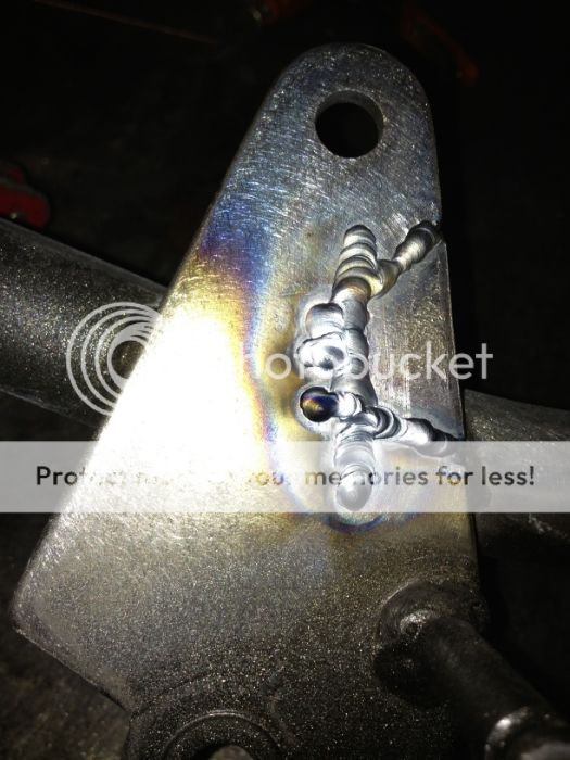
5. Dropped the bungs in, welded them in place, and ground off the welds to achieve the finished look I was envisioning.
Rear set mounts.
1. I machined the bungs (also of Chrome Alloy. I ordered the fixed position Tarozzi's. If someone drops the bikes I don't want the bung threads to be the failure point).
2. Dropped $40 on a step drill because I made a mess of enlarging the master cylinder holes due to having improper equipment.
3. Drilled the holes in the subframe.
4. Tacked the bungs in place, and carefully ensured they were straight.
I believe I started working on the project at about 9 AM Monday morning. And finally called it a week at 10 PM on Friday. In between I did little besides eat, sleep, think about motorcycles, and work on motorcycles. For the subsequent two weeks I didn't even want to look at the project. There is still some finishing to do on all of this, but overall I think I am pretty happy with the results (still haven't looked at the project much). I guestimated the foot peg location based on looks and trying out the feel with the pegs mounted a bit further back on the original muffler/passenger peg mounts. I am not sure I guess right, but we will find out. I can always redo these pretty easily if need be. I really need to find a smaller rider that can help me sort out the right rider position, since I have concluded that this bike will be for some uber-luck girlfriend.
-rear set shift linkage bearing assembly
-rear master brake cylinder re-relocation mounts
-rear set lower frame rail mounts.
Rear shift linkage fab:
1. I ordered a number of different bearings before finding the right one for my rear shift linkage plan. The one I identified has an OD of 25mm, and ID of 10mm, and has internal two ball bearing races that provide great lateral stability. The marker points at the winner.
2. With this identified. I ordered up some chrome alloy tubing (due to the structural significance) to machine the bearing journal from. Here is the machining process. Chrome Alloy machines beautifully btw, provided you have carbide tooling to work with.
3. I then re-cut a recess out of the lower frame rail for the bearing assembly
4. And welded the assembly in.
5. Following this I separated the press fit on the original shift foot control.
6. and machined down the spindle to be compatible with my bearing's ID. This was slightly disconcerting.
7. End Result (kind of)
Rear Master Cylinder Re-Relocation:
1. Bungs fabed from mild steel solid bar stock (center four objects)
2. The bungs recess the bolts such that they will provide a very clean finished look that matches the lower frame rail joint design.
3.Approximate new location
4. To ensure everything was properly aligned I used a mill to drill the holes in the frame:
5. Dropped the bungs in, welded them in place, and ground off the welds to achieve the finished look I was envisioning.
Rear set mounts.
1. I machined the bungs (also of Chrome Alloy. I ordered the fixed position Tarozzi's. If someone drops the bikes I don't want the bung threads to be the failure point).
2. Dropped $40 on a step drill because I made a mess of enlarging the master cylinder holes due to having improper equipment.
3. Drilled the holes in the subframe.
4. Tacked the bungs in place, and carefully ensured they were straight.
I believe I started working on the project at about 9 AM Monday morning. And finally called it a week at 10 PM on Friday. In between I did little besides eat, sleep, think about motorcycles, and work on motorcycles. For the subsequent two weeks I didn't even want to look at the project. There is still some finishing to do on all of this, but overall I think I am pretty happy with the results (still haven't looked at the project much). I guestimated the foot peg location based on looks and trying out the feel with the pegs mounted a bit further back on the original muffler/passenger peg mounts. I am not sure I guess right, but we will find out. I can always redo these pretty easily if need be. I really need to find a smaller rider that can help me sort out the right rider position, since I have concluded that this bike will be for some uber-luck girlfriend.
Earlysport
New Member
Some very nice work and I'm very jealous of what seems like a very well equipped workshop! Laser/water jet cutter? I wish! Regardless it's nice to see such quality work put into details that the less informed wouldn't even notice. Looking forward to seeing the final result ")
Earlysport
Earlysport
Macbethpoe
Ride safe
Just read your whole thread, awesome work man, this gave me some serious motivation to get going on mine, thanks.
zachattach
Project Doldrums
Yes, I had amazing shop resources and amazing people to teach me how to take advantage of those resources. For that I am happy to drop a plug for this company: http://techshop.ws/
If you are lucky enough to live in one of the cities where they are active you can have the same...for a price of course.
Back to cafe racer builds!
If you are lucky enough to live in one of the cities where they are active you can have the same...for a price of course.
Back to cafe racer builds!
zachattach
Project Doldrums
So I really don't want to put this back on:
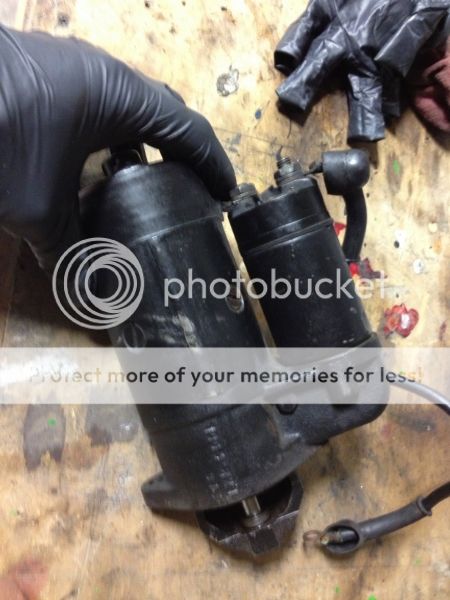
It seems like complete overkill. I bet it could turn over my car. I know kickstart kits were made for the v50, which could be one alternative, but I really do want a starter. Just not one that weighs 30lbs.
Anyone have any recommendations on a good replacement starter-solenoid package that I could retrofit in place of the original behemoth? And any thoughts on what this might all involve?
Macbethpoe
Ride safe
Come on go kick only!
zachattach
Project Doldrums
Ha ha. Good heckling. Tracking down one of the kickstart kits isn't going to be easy.
zachattach
Project Doldrums
Don't know what that is, but it sounds like a great idea. I will begin researching.
Many thanks.
Many thanks.
all the modern cars and motorcycle use a gear reduction starter
this allows a much smaller starter motor and battery
there are still some starter generator alternator rebuilding shops around i used to work in one they will have racks and racks of cores...... time to make some friends
this allows a much smaller starter motor and battery
there are still some starter generator alternator rebuilding shops around i used to work in one they will have racks and racks of cores...... time to make some friends
Speedfreak
New Member
zachattach said:So I really don't want to put this back on:
Hi Zachattach,
I have a Mitsubishi starter motor on My 850 Guzzi Café Racer weight is 50% less than original. I bought it from a member of the Dutch Moto Guzzi forum, he bought it on the internet from a guy in Germany who special designed a gear reduction drive for the Mitsubishi starter motor.
so maybe you can find one at the WWW by searching for Mitsubishi starter motor for Moto Guzzi
Grtz Frank,
The only kick-starter V50 Guzzi's were special made for the army models witch they call NATO's over here in Europe, gear ratio is smaller (more revs, less speed) then stock V50 its more like V35.
zachattach
Project Doldrums
Well, this project is turning into a road show, and I doubt it is over yet. Current project road map:
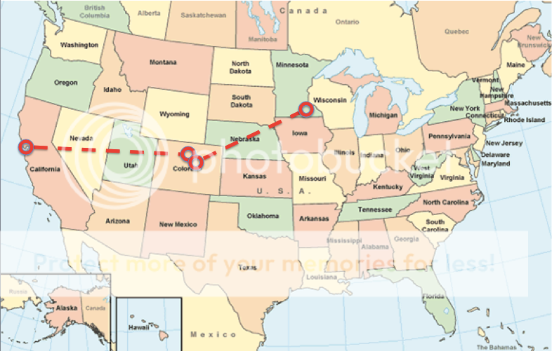
Yes, the project and basically I now reside in my parents' garage in Rochester, MN. With functional workspace, ample free time, a small pile of cash (bye bye BMW), a cat for company, and a beer fridge, I have been making headway, despite one minor impediment:

Yes, the bone I broke last winter didn't heal quite right, and thanks to a recent surgery I am now the proud owner of some titanium bits and pieces...and an temporarily immobilized lefthand...
So, what have I been up to?
Well, I realized that I am getting to a point where decisions are going to effect the riding experience, and I want to get this dialed before I dig further into cosmetics. this realization in mind, my sights are set on making this the v50 run. Once I can drive it, I am then going to tune the riding experience. As I said in one of the very first posts in this write up, I used to race mountain bikes, and through this, I have decent sense of how to find, tailor, and perfect the riding experience. With that dialed I will then return to the final finishing. This seems correct right? A paint job needs to reflect the soul of a bike, and I won't be able to fully get to know the little Guzzi's soul riding it.
Towards those strategic ends:
The first task I targeted upon getting the project moving again was to replaced the starter with a gear redux unit. Thank you to all who chimed in with advice on that topic. It proved a cheap, weight saving, direct bolt on solution.
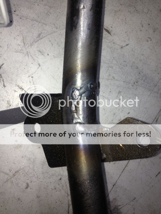
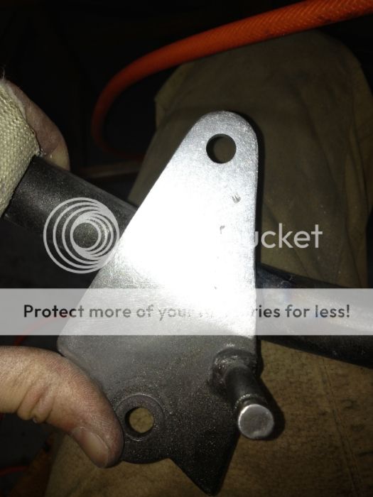
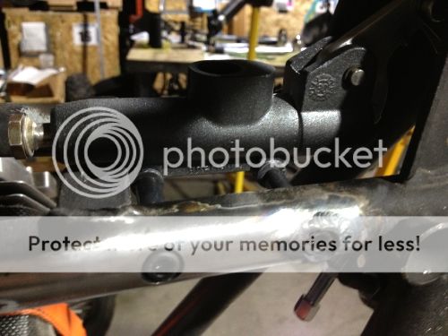
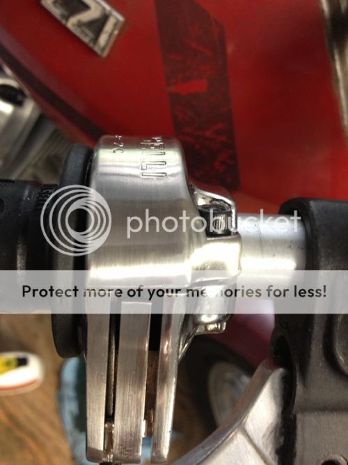
Next, I set to work cleaning up some of the work I did earlier this year on the shift linkage solution I had devised to support the rear sets. The tubing I had welded into the lower frame rail to hold the linkage bearing need to be trimmed back. It started at this length:
And with a dremel tool and a file I slowly trimmed it back and cleaned things up:
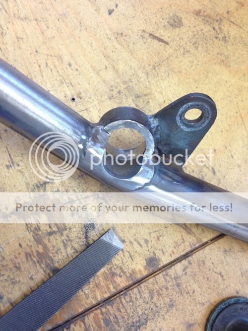
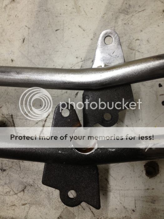
To this:
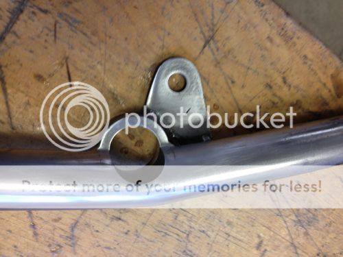
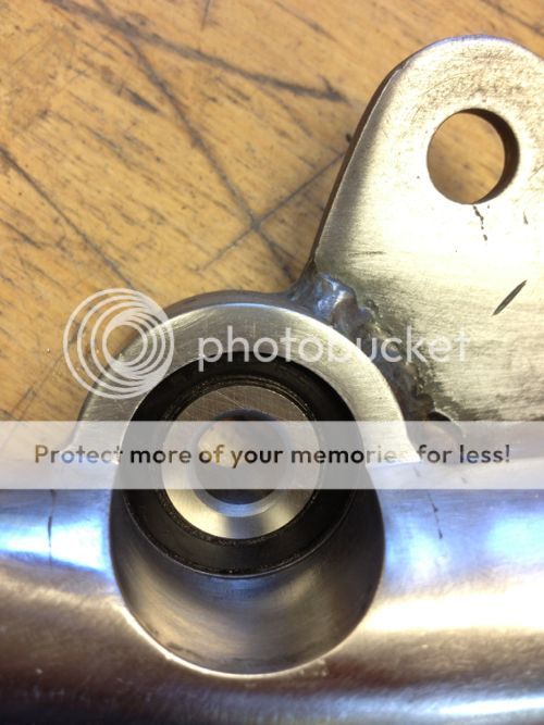
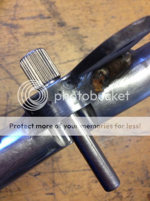
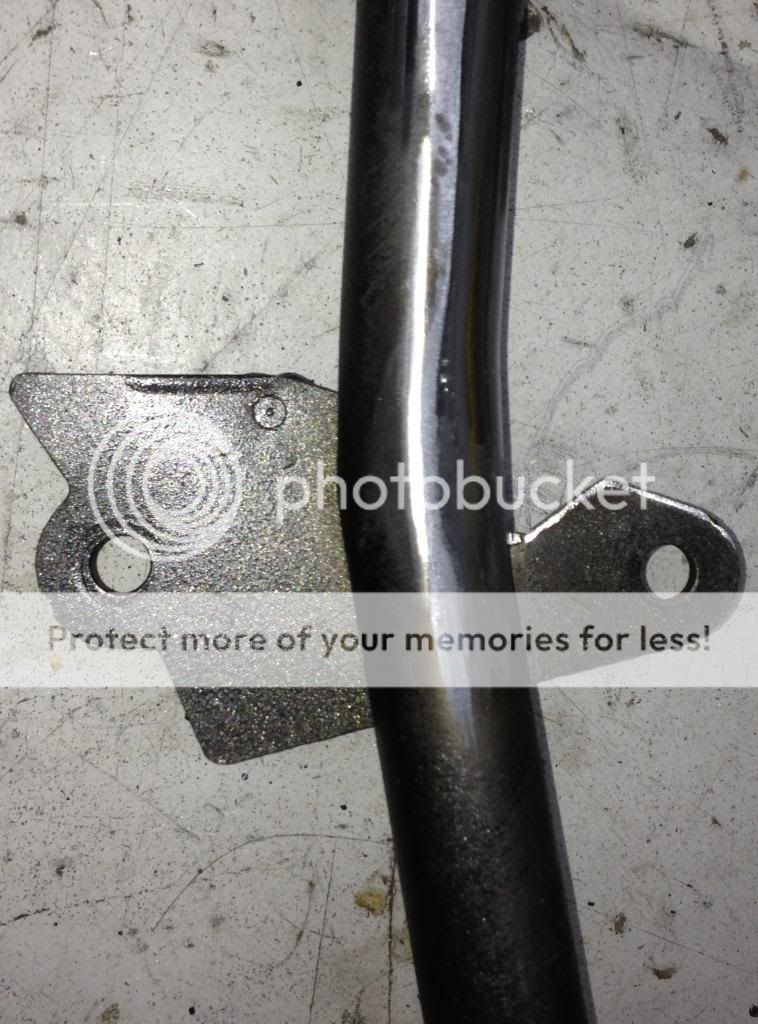
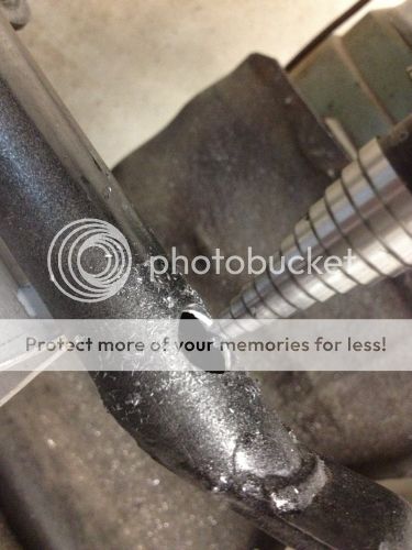
A linkage arm, which I have friend machining for me, will ultimately sit in the recess the trimming created on the far side of the frame rail from the arm seem in the following pic:
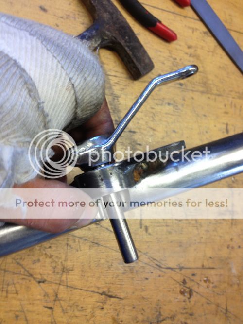
Should be a pretty sexy setup once all is done and said.
With that done and the shift arm on order, I turned my attention to the hand controls. I since I saw dale do it in his post I have been dying to remove up the bar clap mounts from the upper triple tree for years, and despite disavowing cosmetic work, I allowed myself this.
From this:
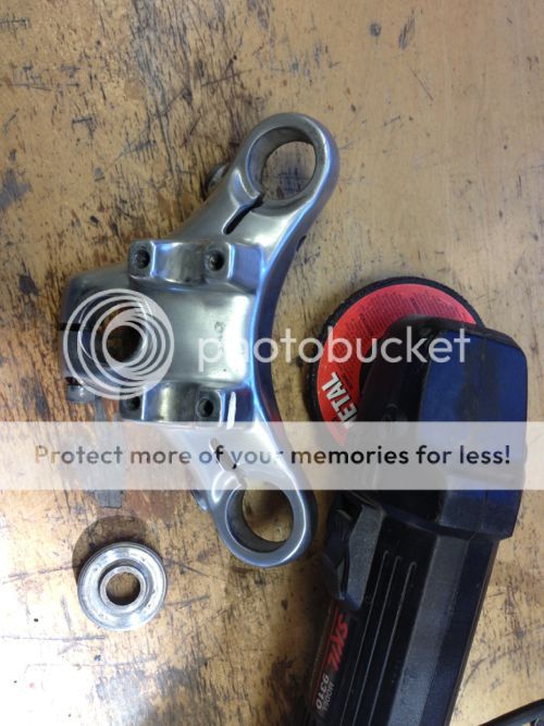
to this
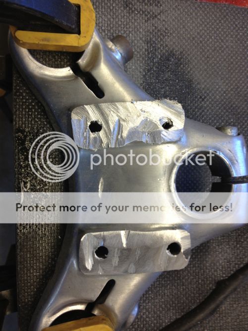
to this
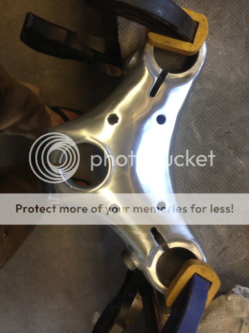
This was absurdly satisfying. I am planning to fill the holes partially, and to take advantage of the threads remaining on the bottom side to attach a gauge bracket that reaches out and up from below the tripple tree. More on that in upcoming weeks.
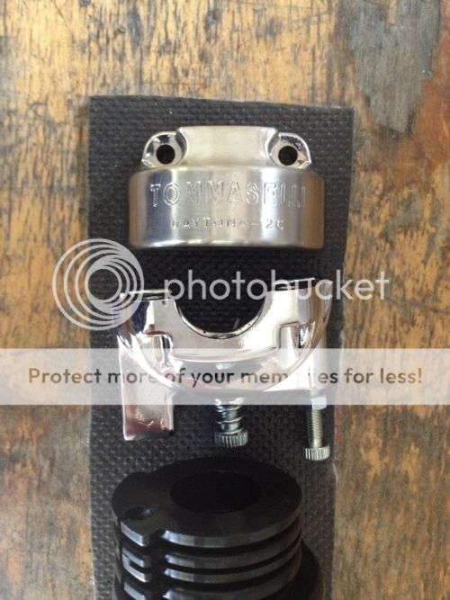
I also picked up a Tommaselli and immediately put a brushed finish on it:
Without electronics the handle bar controls cant be finished, so I set my sites on the electronics next.
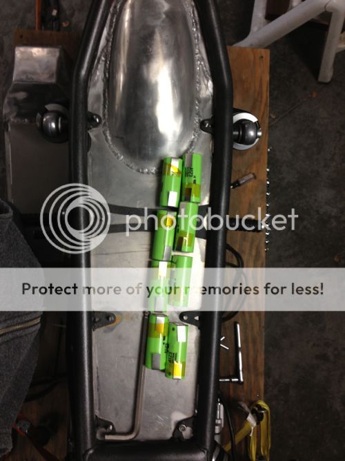
Here is the under seat layout I am planning for the electronics:
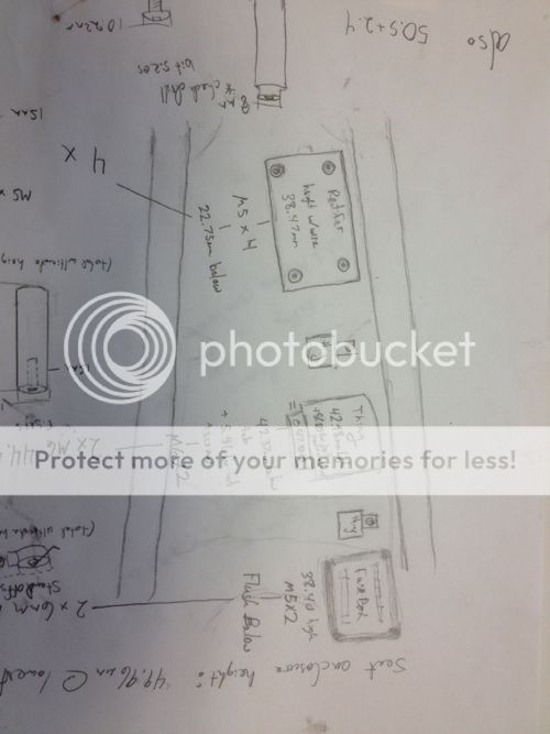
Of the electronics will be elevated up off of the seat pan with aluminum spacers another friend is turning for me. Adjacent to the row of electronics will be a Li battery composed of these:
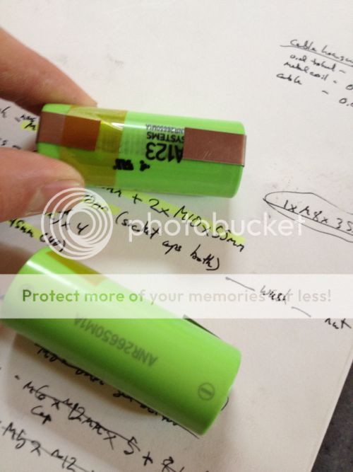
I love that they are neon green.
Everything should tuck under the seat there nicely:
Now it is wiring harness time....
I thoroughly enjoy making sense out of chaos and this:
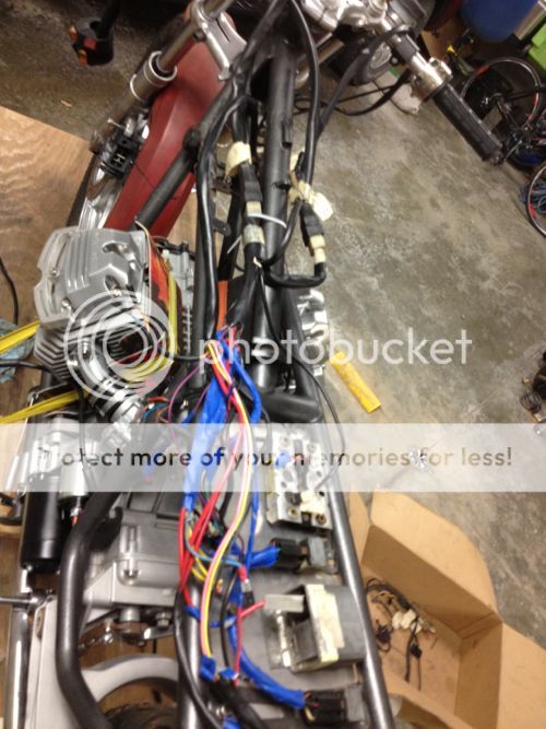
will provide ample opportunity for that.
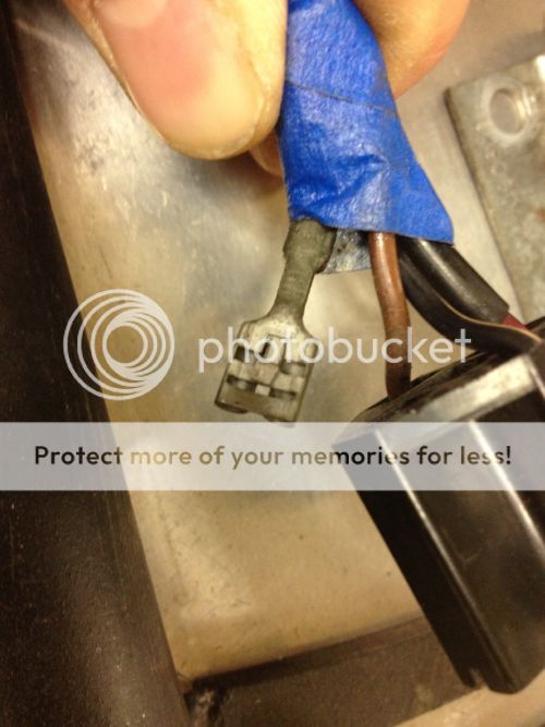
From now until my next post I will be sorting the electronics. If you are reading this and you have suggestions on where to buy the wire I will need and the connectors I will need I could use some direction. I am especially worried about finding the blade connectors that work with the plastic housings of the factory wiring harness. These guys (note the little tab to secure it in the plastic plug is bent in the wrong direction):
Yes, the project and basically I now reside in my parents' garage in Rochester, MN. With functional workspace, ample free time, a small pile of cash (bye bye BMW), a cat for company, and a beer fridge, I have been making headway, despite one minor impediment:
Yes, the bone I broke last winter didn't heal quite right, and thanks to a recent surgery I am now the proud owner of some titanium bits and pieces...and an temporarily immobilized lefthand...
So, what have I been up to?
Well, I realized that I am getting to a point where decisions are going to effect the riding experience, and I want to get this dialed before I dig further into cosmetics. this realization in mind, my sights are set on making this the v50 run. Once I can drive it, I am then going to tune the riding experience. As I said in one of the very first posts in this write up, I used to race mountain bikes, and through this, I have decent sense of how to find, tailor, and perfect the riding experience. With that dialed I will then return to the final finishing. This seems correct right? A paint job needs to reflect the soul of a bike, and I won't be able to fully get to know the little Guzzi's soul riding it.
Towards those strategic ends:
The first task I targeted upon getting the project moving again was to replaced the starter with a gear redux unit. Thank you to all who chimed in with advice on that topic. It proved a cheap, weight saving, direct bolt on solution.
Next, I set to work cleaning up some of the work I did earlier this year on the shift linkage solution I had devised to support the rear sets. The tubing I had welded into the lower frame rail to hold the linkage bearing need to be trimmed back. It started at this length:
And with a dremel tool and a file I slowly trimmed it back and cleaned things up:
To this:
A linkage arm, which I have friend machining for me, will ultimately sit in the recess the trimming created on the far side of the frame rail from the arm seem in the following pic:
Should be a pretty sexy setup once all is done and said.
With that done and the shift arm on order, I turned my attention to the hand controls. I since I saw dale do it in his post I have been dying to remove up the bar clap mounts from the upper triple tree for years, and despite disavowing cosmetic work, I allowed myself this.
From this:
to this
to this
This was absurdly satisfying. I am planning to fill the holes partially, and to take advantage of the threads remaining on the bottom side to attach a gauge bracket that reaches out and up from below the tripple tree. More on that in upcoming weeks.
I also picked up a Tommaselli and immediately put a brushed finish on it:
Without electronics the handle bar controls cant be finished, so I set my sites on the electronics next.
Here is the under seat layout I am planning for the electronics:
Of the electronics will be elevated up off of the seat pan with aluminum spacers another friend is turning for me. Adjacent to the row of electronics will be a Li battery composed of these:
I love that they are neon green.
Everything should tuck under the seat there nicely:
Now it is wiring harness time....
I thoroughly enjoy making sense out of chaos and this:
will provide ample opportunity for that.
From now until my next post I will be sorting the electronics. If you are reading this and you have suggestions on where to buy the wire I will need and the connectors I will need I could use some direction. I am especially worried about finding the blade connectors that work with the plastic housings of the factory wiring harness. These guys (note the little tab to secure it in the plastic plug is bent in the wrong direction):


