Ton up SR250: 100mph, 100kg, 30hp

teazer said:
That would work. Might be better if the linkage were machined in a stepped shape to allow the actuating rod to be straight.


Exactly. I figure if I am going to be drawing up a custom linkage for the rearset (to create mounting points for the return spring and the brake light switch on the underside), I may as well include some smart geometry to reduce the offset in the z axis.
 
Over the weekend I managed to find some stainless threaded rod at a local hardware store, plus some stainless tube that fits it exactly - a little bit like the kits you can get from DCC or Lowbrow customs - except they come with alloy tube.

I think this will do the trick - should be well strong enough. Also, in the last pic, you see the linkage bracket that I will redesign to include some of the required offset plus a spring connection on the underside.
 

Attachments

  • RearsetLinkages1.JPG
    RearsetLinkages1.JPG
    415.8 KB · Views: 212
  • RearsetLinkages6.JPG
    RearsetLinkages6.JPG
    220.4 KB · Views: 210
  • RearsetLinkages5.JPG
    RearsetLinkages5.JPG
    141.9 KB · Views: 201
  • RearsetLinkages4.JPG
    RearsetLinkages4.JPG
    142.6 KB · Views: 198
  • RearsetLinkages3.JPG
    RearsetLinkages3.JPG
    155.7 KB · Views: 204
  • RearsetLinkages2.JPG
    RearsetLinkages2.JPG
    449 KB · Views: 234
out of curiosity, why go with stainless tube if you're concerned with weight, I imagine it's almost 3x as heavy even if it's not much. also - I used carbon fiber tube on my brake actuation rod for my bike, it's stronger than the alloy - nearly impossible to bend and took quite a bit to break in the harbor freight press.
 
MiniatureNinja said:
out of curiosity, why go with stainless tube if you're concerned with weight, I imagine it's almost 3x as heavy even if it's not much. also - I used carbon fiber tube on my brake actuation rod for my bike, it's stronger than the alloy - nearly impossible to bend and took quite a bit to break in the harbor freight press.

Carbon fiber would only work if the rod could be completely straight - I need two bends in this case. Unless you laid up the carbon yourself to the shape/bends you wanted?

The stainless is heavier yes, but by very little - it has a 1mm wall thickness as opposed to the aluminium tubes 1.5mm wall - which evens out the weight diff a lot. I figure I want this linkage to be strong and because this rod will save at least 500g over the original linkage idea (with two rods plus a linkage arm, plus a pivot axle).
 
LOL, Carbon fiber is too expensive for me but I would love to use it if I had enough cash. I used stainless link rod on mine as I had some stainless bar and it's way stronger than 6061. A 6061 link is pretty ugly in a size that doesn't flex too much but for a torque arm isn't too bad in tension. I'm finally in the process of completely re-doing 360 (378) Chassis weight is only a disadvantage for acceleration or up hill, SR isn't going to be too worried about a few extra pounds cornering (unless it's in a top box way high and way out back)
Sorry to burst your bubble but a more realistic number for an SR250 motor is going to be 20bhp until you spend mega money and even then 25bhp will probably be 'top' number' It's great fun to learn tuning on a single but even buying just one of everything gets expensive when you start breaking stuff. You will need a 'race' cam, probably modified rockers, oversize valves, lot of flow bench time (couple of spare heads needed) forged piston and probably a connecting rod upgrade unless you can get forged pistonway lighter than stock.You'll also need some math to do inertia and stress comparisons (cheaper than breaking stuff) It cost around $3,000 to get 24bhp from a Honda XR200 (about 7bhp over claimed output, nearer 11bhp in reality), 'flash dyno reading and then rod snapped. The 200 was 'quite reliable' at 22bhp, the extra 2bhp needed just a few too many rpm. I think I could have removed enough weight from piston and gudgeon pin but development stopped at 22 with some reliability and 'bolt on parts' that didn't require extra machine work.
 
Thanks for your input crazy. You might be right about the power, but we'll see how things go with the mods I have done - many of which are ones you mention and are already done.

Also true about the weight reduction. A lot of the small stuff I do now won't help with top speed or handling really. But I must admit it has become a bit of an obsession so I may as well run with it until I run out of energy or funds or time, whichever comes first. It's challenging and fun.

Just as a side not, the intake and exhaust system I designed for these engines gives a 20% power boost - this is verified on two different dynos, different days, different operators. So to get 50% more power with a lot (a lot) of work just may be possible. Heres to trying ;)
 
I decided to buy in the needed electrical stuff to complete the project - so I can start planning the wiring as well. There were a bunch of speedo's I looked into but the Velona 80 from Daytona has a rev counter and idiot lights as well - no need for any extra dash items, nice.

The blinkers I have used on another couple of bikes and really like them - they are super bright and small and only cost 30Euro a set. They are exactly the same as other ones online for 70Euro a set, just that these are bought in bulk by Biltema so can be sold at this price point.

The tail light I am not so sure about but it is growing on me. I like the size and the fact that the underside shines clear onto the license plate.

Hopefully get some time in the workshop over the coming weekend!
 

Attachments

  • SR250_ElectricComponents.JPG
    SR250_ElectricComponents.JPG
    433.2 KB · Views: 252
Cool stuff designing exhaust system. OEM is always compromised by rules and regulations plus having something that will fit. In my experience a design that gives a power boost always acts as an amplifier at working rpm. Quieting it down doesn't automatically mean a lot less power though
 
Did a bunch of stuff over the weekend (last weekend) and just posting now. I tried making my own slide hammer to pull the tank dent - by gluing the end to the dent and hammering. Failed miserably. Lots of things wrong with it. Anyway, decided to order a dent puller kit from ebay for 8gbp, be interesting to see if it works.

I also prototyped the rearset linkage bracket a couple times and think it will work good. Managed to get in all the details it will need plus a nice 25mm offset so the linkage rod doesn't have to be bent so much.
 

Attachments

  • IMG_0140.JPG
    IMG_0140.JPG
    336.6 KB · Views: 223
  • IMG_0139.JPG
    IMG_0139.JPG
    458.1 KB · Views: 206
  • IMG_0138.JPG
    IMG_0138.JPG
    467.1 KB · Views: 216
  • IMG_0137.JPG
    IMG_0137.JPG
    293.9 KB · Views: 209
  • IMG_0136.JPG
    IMG_0136.JPG
    287.1 KB · Views: 193
  • IMG_0135.JPG
    IMG_0135.JPG
    345.2 KB · Views: 206
  • TankDent2.JPG
    TankDent2.JPG
    344 KB · Views: 198
  • TankDent1.JPG
    TankDent1.JPG
    290.1 KB · Views: 209
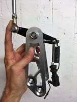
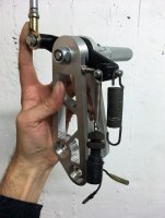
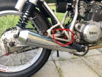
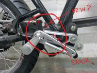
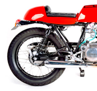
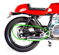
Having plowed a fair bit of this ground myself, I have a couple of observations. There is a lot to be said for a linkage system, but there is a requirement that is often so difficult to meet that a cable starts looking very appealing. The issue is a result of the suspension motion. In order for the action of the pull rod to be constant while the suspension moves, the pivot point where the crank arm connects to the pull (or push) rod must be coincident with the swing arm pivot. Any other location introduces undesirable motion into the braking system as the suspension moves. Obviously this is impossible to achieve, as the pivot is not stationary, and can only be ideal at one brake pedal location. Fortunately, the problem is a matter of degree, so as long as the problem is small enough so as to be (mostly) unnoticeable, it is not a problem. Unfortunately, there is a quite limited range of locations for this pivot where this problem is, well, not a problem. The stock location is pretty much the only good place. On virtually all bikes, you will find this location as close to the swing arm pivot as practical, and very close to or on, a line drawn between the swing arm pivot and the rear axle. Even very small deviations from this location will create obvious problems with the brake actuation as the suspension moves, though the seriousness of the problem often depends on who you ask. Moving this pivot point fore and aft along the center to center line is fairly benign. Moving it up or down off of this line is not. Your location is high enough to be very noticeable to your foot if you apply the brake and have substantial suspension motion at the same time. Opinions vary. On a street bike it might only be an annoyance, but it would be intolerable on a road race bike. The farther away from the center to center line, the worse this will be, and if far enough away combined with sufficient suspension travel, it is even possible to lock the brake even with zero pedal on a hard enough bump.
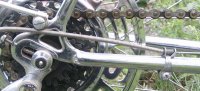
You can see how this works by taking off your shocks and while observing your brake pedal, moving your suspension up and down. You will have to first adjust your brake to be off of its return stop to see the motion. In operation, with the brake applied, you will feel the mechanism "pumping" as you travel over bumps. This phenomenon is present in ALL similar mechanisms, even stock configurations, but it is small enough that it is unimportant.
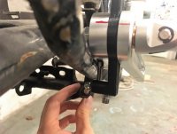
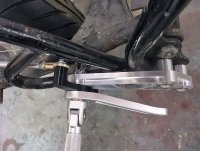
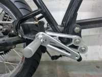
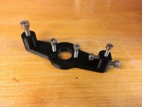
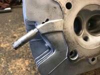
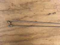
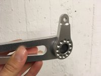
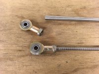
From the pics, it looks like you can lower this pivot to fall along the center to center line, in which case the issue will become insignificant. When I put a bike together, I determine where the pegs need to be and that is where they stay. If you are committed to the current peg location, keep in mind that the brake pedal axle need not be part of the peg. And if you have not already given consideration, the lever ratios are very important. It is very useful to measure the stock brake pedal length, along with the length of the lever that connects to the pull rod. You will need to keep this ratio, as well as the ratio between the lengths of arms at both ends of the pull rod in your new system if you want similar power required at the pedal for operating the brake. Just because this system is very simple, it does not mean there is not a lot to figure out if you want it to function well, and the fact that all stock systems are so very identical is worth considering. There is in fact very little deviation possible without real consequences, which is why cable or hydraulic systems are often the "go to" solution despite their increased complexity and expense.
 
Thanks for the input mobius. You managed to explain what I have discovered/realized with this linkage during this process. A mechanical linkage, no matter how 'optimal' will always be 'sub-optimal' in this particular application. And I agree, a cable set up would be much better. I think I'll weld a cable holder to the swingarm before powder coating it - just in case I need to redesign the rear set linkage and go down this route - I will try the mechanical linkage first. Besides, as you mention 'On a street bike it might only be an annoyance, but it would be intolerable on a road race bike' - absolutely true. A road racer would be using the rear brake a lot more eloquently than myself and would be annoyed by the weird feedback through the foot peg from the swingarm action. But I don't (hope) think I will notice it too much. Having the backup plan for a cable system already welded on place will give me piece of mind.

Check out the attached images for comparison of stock position for the brake link rod and the new position plus a forward moved suggestion position - which with the brake arm lever flipped upside down, would be a similar/comparable position to stock.
 

Attachments

  • SrBrake_Stock.jpg
    SrBrake_Stock.jpg
    2 MB · Views: 216
  • SrBrake_New.jpg
    SrBrake_New.jpg
    1.5 MB · Views: 208
Maybe I need need to weld on a 'cable stop' as they are called. Looks like there is a bunch of either bolt on (drill and tap holes) or clamp on solutions available...
 

Attachments

  • Stops in Place.jpg
    Stops in Place.jpg
    37.8 KB · Views: 203
  • MySekineSHT_CableClampChainStay.jpg
    MySekineSHT_CableClampChainStay.jpg
    94.5 KB · Views: 210
  • GDjxC.jpg
    GDjxC.jpg
    13.9 KB · Views: 510
  • 24826.jpg
    24826.jpg
    41.9 KB · Views: 564
On a very different note, I got a couple of update messages from Chris this week. He said the exhaust thread detail in the head was too risky to weld up - too much heat distorting the head and too thin aluminium there. So instead he turned up an insert and threaded that in place (and added epoxy) then re-tapped that. It looks good!

Plus he has installed custom bronze valve guides and turned up the custom Ti valves 8) 8) 8)

So happy there are pros that do this kind of specialised stuff, it is way out of my league.
 

Attachments

  • SR_TitaniumValves.jpg
    SR_TitaniumValves.jpg
    46.7 KB · Views: 605
  • SR250_BronzeGuidesHead.jpg
    SR250_BronzeGuidesHead.jpg
    61.5 KB · Views: 593
  • SR_BronzeValveGuides.jpg
    SR_BronzeValveGuides.jpg
    100.6 KB · Views: 598
  • SR_ExhuastThread3.jpg
    SR_ExhuastThread3.jpg
    55.2 KB · Views: 581
  • SR_ExhuastThread2.jpg
    SR_ExhuastThread2.jpg
    55.3 KB · Views: 590
  • SR_ExhuastThread1.jpg
    SR_ExhuastThread1.jpg
    59.1 KB · Views: 566
I’m watching this build with interest. I built an SR250 cafe racer (which Rex Havoc finished off) and always wanted to do more to the engine. I just didn’t have the resources at the time.

Great methodical work!
 
lunacy said:
I’m watching this build with interest. I built an SR250 cafe racer (which Rex Havoc finished off) and always wanted to do more to the engine. I just didn’t have the resources at the time.

Great methodical work!

Whoa, things really have come full circle! One of the main reasons I ever got interested in and started working on SR250's was because of your build thread back in 2008! So I have a lot to thank you for sir. And now you're commenting on my build thread, priceless.

I remember being almost heartbroken when you declared that you wouldn't be able to finish the bike yourself and that you had to sell it on. It was cool to see it get finished and featured on Pipeburn though.

Yes, I am doing quite a few interesting engine mods for this build so I am really curious to see how it all pans out :D
 
And while I've got you here... I notice on your bike you had a similar brake linkage set up! I guess the bike was long out of your hands by the time it was being ridden and therefore cannot comment on its action/feel/performance? The brake specifically I mean.
 

Attachments

  • Brake.PNG
    Brake.PNG
    777.6 KB · Views: 515
  • InkedBrake_LI.jpg
    InkedBrake_LI.jpg
    717.2 KB · Views: 531
Personally I've never been a fan of reversing the operating lever like that or having rod pivot point too far from swing arm pivot. Always found it made brake 'grabby' (putting main pressure on leading shoe instead of trailing shoe) and the suspension operation was very noticeable
 
Back
Top Bottom