
We noticed you are blocking ads. DO THE TON only works with community supporters. Most are active members of the site with small businesses. Please consider disabling your ad blocking tool and checking out the businesses that help keep our site up and free.
You are using an out of date browser. It may not display this or other websites correctly.
You should upgrade or use an alternative browser.
You should upgrade or use an alternative browser.
1974 CB360 - first bike/build
- Thread starter huck_finn
- Start date
huck_finn
Been Around the Block
Got the capacitors in, but I also just found out that my wife decided to get me an m-unit & m-button for my birthday. Yeah, I was pretty surprised & excited. So I am going to hold off on the capacitors until I get everything wired up through the m-unit.
I am glad she didn't get me the one with bluetooth...I don't want to deal with that crap.
I am glad she didn't get me the one with bluetooth...I don't want to deal with that crap.
huck_finn
Been Around the Block
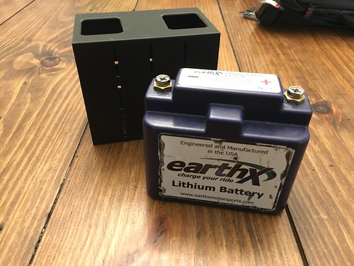
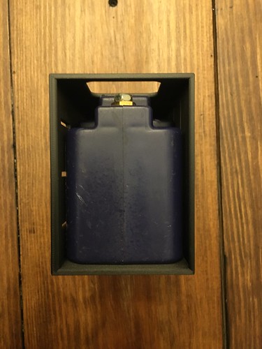
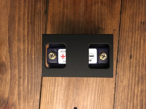
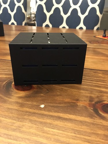
The electronics tray warped when it was printed - so they didn't charge me for it. I took it home to see how I did with my measurements, and I found out that I have some more room to play with (width, depth, and length). The tech in the lab is going to try and setup the larger printer to use some the onyx filament to hopefully get a better print. I will probably bring the tray down to the bottom of the stock air box mount tab.
I am going to have to make some modifications to the rear inner fender - or just make a new one - in order to get the battery box all the way to the back of the tray. Does the wheel travel in far enough to need the curve in the fender, or can I just use a flat piece of steel?
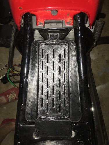
I am going to have to make some modifications to the rear inner fender - or just make a new one - in order to get the battery box all the way to the back of the tray. Does the wheel travel in far enough to need the curve in the fender, or can I just use a flat piece of steel?
I don't think the wheel could come up so far that a flat peice would contact - even with my bike as low as it is, it could never hit something flat on the inside of the frame
huck_finn
Been Around the Block
MiniatureNinja said:I don't think the wheel could come up so far that a flat peice would contact - even with my bike as low as it is, it could never hit something flat on the inside of the frame
Awesome! I have a sheet sitting in my garage that will be perfect.
crazypj
Split personality, I fake being smart
You can't use a flat piece across the 'diagonals. Take shocks off and lift wheel to see where it's going to end up (or use a bar drilled at 9-1/2" centers) You need a minimum of 3/8" clearance at 'full bump' to allow for various things flexing (they will)
crazypj
Split personality, I fake being smart
I cut a small section out of front lower plastic piece as I mounted battery to the tool box mounting brackets. Wasn't too concerned as steel battery box would need a substantial 'smack' to damage battery but I have had things 'go round with the wheel' in the past and get stuck on swing arm
huck_finn said:Okay - that makes sense. I also didn't think about how fender sits between the swing arm until I got home tonight to take a look.
a small curve in the sheet shouldn't be hard to make, and will make certain no contact occurs. I don't see how it could contact, like I said - my bike can't contact a sheet there. but I realize now thinking about it that I have a longer swingarm, so that may be why
crazypj
Split personality, I fake being smart
Brendon used a flat sheet with curve on his 360, wheel gets close but doesn't touch.
I think we drilled a couple of 5~6mm holes in original side mounts, the curve plus only 2 bolts stops things moving around or vibrating too much
It gave him somewhere to put various stickers ;D
Reply 714 just after we finished putting it together
http://www.dotheton.com/forum/index.php?topic=11736.700
huck_finn
Been Around the Block
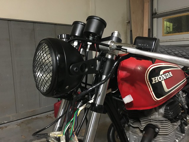
Slow going as of late. My m-unit came in (v2, no bluetooth), along with an m-button. But I haven't had time to do much with it. I went through two more versions of my headlight brackets, they were too long...just like PJ mentioned. My headlight bucket just didn't fill up the space like I had hoped. I shortened them, and got the headlight tucked back as far as I could get it without putting pressure on any of my cables. The first image makes it look like there is about a mile's worth of space that I could have gotten rid of, but you can tell from the second photo that it is pretty snug.
huck_finn
Been Around the Block
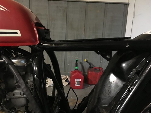
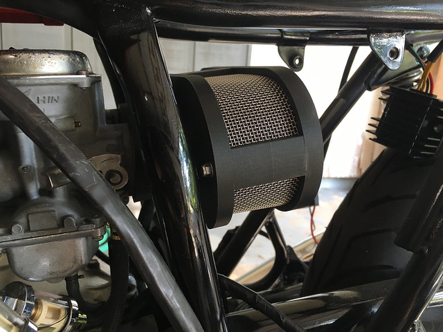
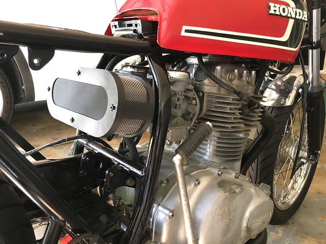
Been a while - despite what most folks believe, summers are way more busy in higher-ed than other semesters. About the only thing I have been able to work on is a first run at my air box and a new seat.
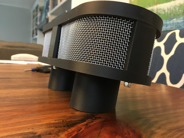
I learned a lot designing the filter - a lot of things weren't apparent until I had something in hand. First thing is that I my next attempt will be built around an off the shelf filter to keep me from having to beat my head against the wall while trying to keep the foam out of the carbs. I also need to figure out a way to run supports from the front plate to the front mount of the battery box to prevent carb sag.
I haven't run the bike with the filter on there - this was really a true test fit. It looks good though.
huck_finn
Been Around the Block
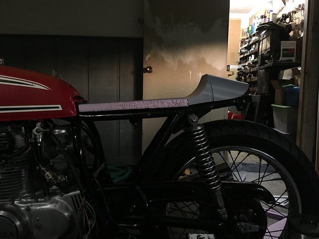
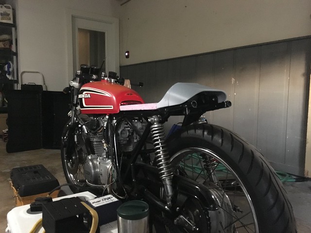
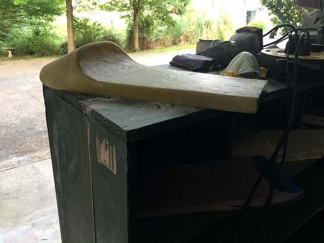
I printed the rear cowl using PLA instead of anything more substantial - since it was just going to serve as a mold. I want to try and keep from cutting too much off the rear of the frame, while keeping the stock rear fender mount in place. The curve in the cowl sits just in front of the rear fender mounts.
I am going to mount the seat on rail that goes across the bike just before the fender rises up, but I need to have another mounting point up front. I am going to use some rubber stops to give me the height and angle I want.
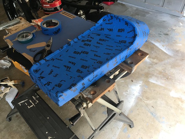
I doubled the foam thickness for my mold, knowing that I would trim any excess off once I started fitting it on the bike. I used some tubing to make the rim of the seat, but it gave me headaches trying to keep everything smooth.
This first attempt isn't going on the bike. After sanding I realized that the air around the tubing caused too many thin/weak spots - and the side rails turned in at the bottom.I would end up having to bondo the crap out of it to make it somewhat close to paintable. I am going to glass the mold again without the tubing tonight and see if I can't get some better lines, because this one looks like garbage.
[/size][/font]
I am going to mount the seat on rail that goes across the bike just before the fender rises up, but I need to have another mounting point up front. I am going to use some rubber stops to give me the height and angle I want.
I doubled the foam thickness for my mold, knowing that I would trim any excess off once I started fitting it on the bike. I used some tubing to make the rim of the seat, but it gave me headaches trying to keep everything smooth.
This first attempt isn't going on the bike. After sanding I realized that the air around the tubing caused too many thin/weak spots - and the side rails turned in at the bottom.I would end up having to bondo the crap out of it to make it somewhat close to paintable. I am going to glass the mold again without the tubing tonight and see if I can't get some better lines, because this one looks like garbage.
[/size][/font]
I made a little stainless bracket that bolts onto the engine mount bracket. Kinda stole the design from Trek and 3D printed a little piece that slips on the end and fits snugly into the castings on the carb. Works great to prevent sag. A few more pics on the second to last page on the build thread.

By the way, that airbox is trick. Nice work.
huck_finn
Been Around the Block
advCo said:I made a little stainless bracket that bolts onto the engine mount bracket. Kinda stole the design from Trek and 3D printed a little piece that slips on the end and fits snugly into the castings on the carb. Works great to prevent sag. A few more pics on the second to last page on the build thread.
Thanks for the compliment, but I am sure I will be chasing my tail with jetting to get it to run close to normal.
Have you had any issues with that bracket you made? Not too much vibration?
huck_finn said:Thanks for the compliment, but I am sure I will be chasing my tail with jetting to get it to run close to normal.
Have you had any issues with that bracket you made? Not too much vibration?
Nope. It hasn't moved a bit. I put a lock washer behind the engine mount bolt and a bit of loctite on it. The carbs feel like they should with a stock airbox on there.
huck_finn
Been Around the Block
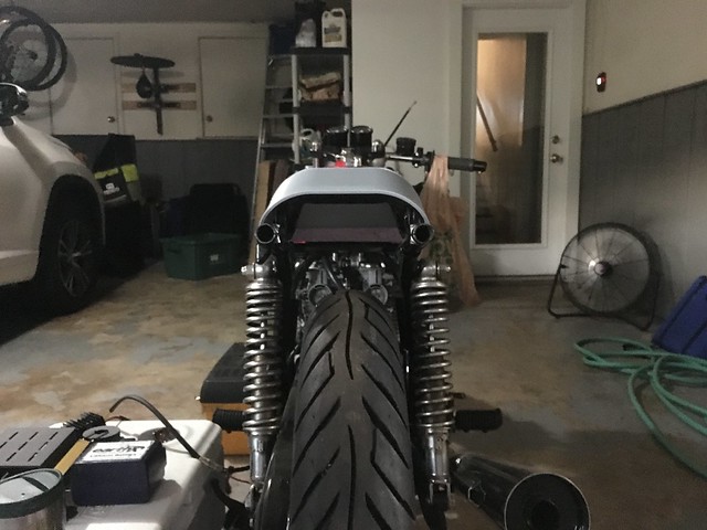
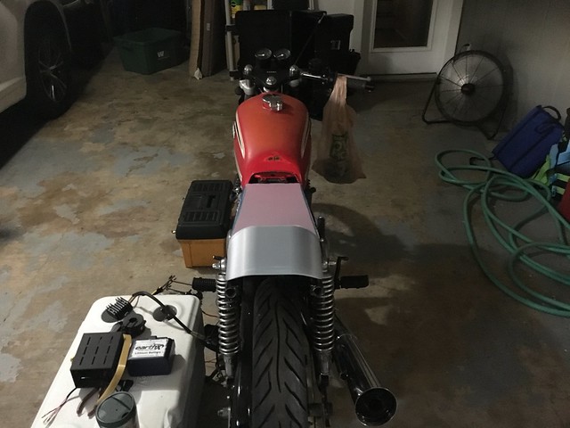
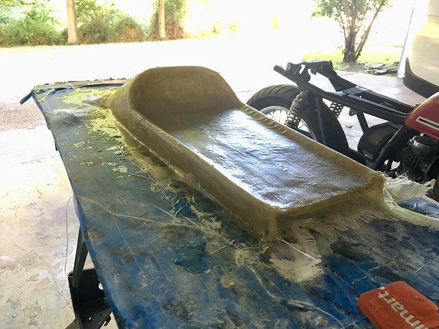
My second seat turned out much better - I removed the lip around the edge of the mold, which made things easier. It still needs a good bit of work - but I pleased with how it turned out strength-wise. I can put my full standing weight on it and it doesn't even blink.
huck_finn
Been Around the Block
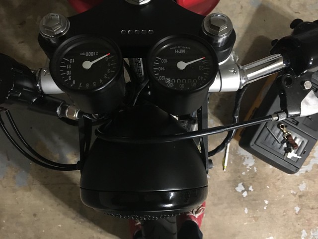
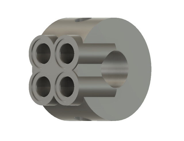
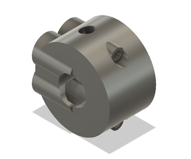
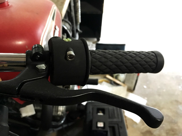
I was also able to go though a few test prints for my handle bar controls. What I have now is the design I will end up having milled out of aluminum at some point in the future. The barrel nuts are in there because I didn't want to risk the bolts pulling out - it is functional, but not the prettiest. When it is milled, they will be removed and I will just use a threaded channel going from front to back.
I am using a four-button setup with my mUnit. There is an m-button stuffed into the handlebar, and the switches I found are from Amazon: https://www.amazon.com/gp/product/B01FKXRYT6/ref=oh_aui_search_detailpage?ie=UTF8&psc=1
And ignore all the fiberglass/resin dust on it - I haven't had the chance to wipe anything down.
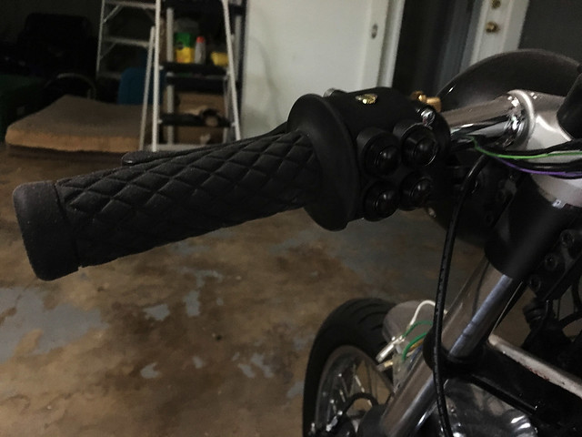
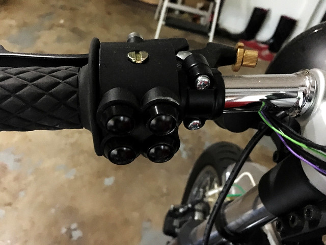


