
We noticed you are blocking ads. DO THE TON only works with community supporters. Most are active members of the site with small businesses. Please consider disabling your ad blocking tool and checking out the businesses that help keep our site up and free.
You are using an out of date browser. It may not display this or other websites correctly.
You should upgrade or use an alternative browser.
You should upgrade or use an alternative browser.
CB360 Airbox design
- Thread starter Bucky685
- Start date
johngofast
Over 1,000 Posts
Will be watching. Very cool.
intrigued!
Bucky685
Been Around the Block
Thanks fellas! I'm excited to see how this runs!!
I'll see what I can do as far as dyno. See how much it would cost to run it on the dyno.
I'm not sure i would be able to compare it to stock. Since i don't think the stock air boxes would fit my frame. (haven't tested the fitment yet. Just guessing)
But testing between pods and this intake could be possible. Hopefully I'll have something final mock up in the next few weeks.
gijoe13844
Coast to Coast
You can adjust length of intake to tune your curves but there are certain intervals you have to hit...you can't just pick any length. Ill see if I can't find the formula for it. I also believe it has to be a straight intake from the carb mouth otherwise you get air going different speeds around bend radii and waste the benefit of the velocity stacks.
Again....not shitting on your idea...i actually really like it but there are things you have to consider to make it work right. the first thing i would measure is the distance from the engine intake port to the end of the factory rubber stack inside the airbox. That will give you the interval that was hit initially.
Again....not shitting on your idea...i actually really like it but there are things you have to consider to make it work right. the first thing i would measure is the distance from the engine intake port to the end of the factory rubber stack inside the airbox. That will give you the interval that was hit initially.
gijoe13844
Coast to Coast
I found this from sonrier....its written for CV carbs but the math still applies to Slides
""""As many of you may already know, CV carbs don't respond well to changes in the intake system that introduce turbulance. Turbulance, mostly, is due to pod filters and other "high flowing" intake systems. The solutions to this problem are numerous and include construction of air boxes to provide "still" air, introduction of air correction systems within the intake itself, and even sticking with the stock air box and making no intake changes whatsoever. For those whose minds are set on a solution that will provide better airflow while still allowing the use of their stock CV carbs (as opposed to a switch to Mikuni VMs or the like) a velocity stack offers itself as a good option. A velocity stack serves a number of purposes. First and foremost, it smooths air flow entering into the intake. Smooth airflow means MORE airflow. Because the air molecules are all heading in the same direction and not fighting among themselves, you can make more air and more fuel into your cylinders. More air and more fuel means more power!
Additionally, in reference to our CV carbs, smooth air means we can tune them more reliably and not be forced to a switch to VMs. The secondary reason to use a velocity stack is to increase the (you guessed it) velocity of the intake charge. This is a good thing because the intake valve is still open when the piston begins its compression stroke (this is especially true for high duration cams). What this means is that if the intake charge is moving too slowing, it won't have enough interia to overcome the increasing pressure in the cylinder caused by the rising compressing piston and the fuel/air mixture will be forced back out of the intake, costing us power due to poorer cylinder filling. Finally, the tertiatary purpose of a velocity stack is to change the length of your intakes. This allows you to create an intake length that will resonate at a certain frequency (RPM). This resonance creates pulses or waves of higher pressures within the intake and the object is to time one of these pulses to hit the intake valve just before it closes. A well designed velocity stack with full taper will accomplish its primary and secondary purposes with little left over for you to worry about and so we will focus the remainder of this document on the resonance effect (also called pulse tuning or ram induction).
Much like small waves lapping up against the edge of a pool and then heading back toward their origin, these resonance pulses will rebound and travel back and forth along the intake tract. The number of bounces the pulse incurs before being utilized by our tuning determines how we address the pulse and also the amount of pressure the pulse creates. For instance, the third time the wave bounces back and forth is called the (funnily enough) third wave or third pulse. Just like any other wave that bounces between objects, much of its energy is spent during the reflection process and so each each higher numbered wave will have much less power than the lowered number wave before it. "Easy!", you say. "I want the most power and so I will tune for the first wave!" Well, that's exactly what we want, in theory, but this is often quite difficult to do in practice. The speed at which these pulses travel is variable depending on your intake conditions, but is roughly the speed of sound (1125 feet per second) minus a bit for any bends or restrictions.
Now lets examine your intake system a bit more closely so we can figure out how to best capture that rebound. Before we begin with the math, decide which range in the RPM you wish to the effect to take place. As with nearly evertything in engine performance, you have to choose a "best" and in order to make the most of your machine you're better off stacking all of these "best" points at exactly the same spot. For argument's sake I will choose 8000 RPM. For the following calculations, I will also assume the stock duration for a Honda 360 which is 221°.
1.) A 4-stoke engine rotates twice for every opening of the intake valve, and so we use 720° as a starting point.
2.) To determine how long our intake valve remains closed, we take 720° and subtract the duration of our cam at 221°. The answer is that the intake is closed for 499° of the crankshaft's rotation.
3.) Now we need to figure out the number of rotations per second by taking our 8000RPM figure and dividing by 60. We have 133.33 RPS.
4.) Now convert this number to degrees per second by multiplying by 360°. We have 48000°/sec.
5.) Next, take the number of degrees the intake valve is closed and divide that by the number of degrees of rotation per second and we have .010395 seconds.
6.) Finally, we take the number of feet per second which the pulse is travelling and multiply that by the number of seconds we calculated at step 5. The answer is 11.695 feet. Now divide this number by two because the pulse which we are measuring is, first, traveling away from the closed intake port and rebounding back to it. This gives us an ideal intake length of 5.848 feet in order to catch the first pulse.
Obviously a six foot intake is going to be longer than many of our bikes and so capturing the first pulse is rarely, if ever, feasible. Even targeting the second pulse can be difficult and NASCAR builders usually aim for third pulse. Depending on your application you should try to get fourth pulse but can settle for as low as sixth. Knowing the necessary intake length for each pulse you capture is as simple as dividing the number we got from step six by the pulse number. For intance, to capture the fourth pulse, we divide 5.848 by 4 and get 1.462 feet, or 17.5 inches. Doable, but still long. Going down to fifth wave gets us 14.0352 inches, so we'll give that a try.
Because this is the total length of the intake and not just the length of the velocity stack, we need to first subtract the existing intake length before we can determine the length of the velocity stacks. The intake length from intake valve to carb venturi opening for a Honda 360 is 214mm. A quick metric conversion from 14.0352 inches minus 214 mm gives us 142.5 mm. So for our particular application, we're looking for velocity stacks that are 142.55 mm in length. Simple, no?""""
Patmanbbe
Been Around the Block
Bucky685 said:From my understanding changing runner length will effect the hp/torque curve. My runners will prob. be about 3-4" longer than stock.
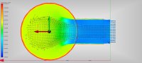
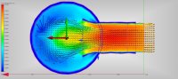
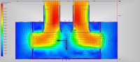
Images show another idea I have for the air box. I feel this would allow the motor to breath much better, than my previous design. While still allowing for the air to "settle" in the plenum before being sucked up into the carbs.
My elbows will be 45 degree eblows vs 90 degree elbows. This would allow less pressure drop over the 90 degree elbow vs 45 degree elbow.
I love the latest design! Its very industrial looking and dig it bro! Looking forward to your outcomes!
Any one have any thoughts on how this design would do on an inline 4 cylinder bike?
Bucky685
Been Around the Block
PatmanBBE said:I love the latest design! Its very industrial looking and dig it bro! Looking forward to your outcomes!
Any one have any thoughts on how this design would do on an inline 4 cylinder bike?
Thank you! I'm guessing because I design industrial gas compression equiptment, might of influenced my design.
mydlyfkryzis
当有疑问时踢你的敌人在生殖器上,你可以道歉后
Bucky685 said:From my understanding changing runner length will effect the hp/torque curve. My runners will prob. be about 3-4" longer than stock.
Images show another idea I have for the air box. I feel this would allow the motor to breath much better, than my previous design. While still allowing for the air to "settle" in the plenum before being sucked up into the carbs.
My elbows will be 45 degree eblows vs 90 degree elbows. This would allow less pressure drop over the 90 degree elbow vs 45 degree elbow.
I like the style, but you realize, the design is very close to the sock airbox in configuration. that is not bad, but actually good....
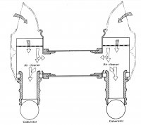
Here's the intake schematic from the CB360 FSM:
Attachments
Bucky685
Been Around the Block
mydlyfkryzis said:I like the style, but you realize, the design is very close to the sock airbox in configuration. that is not bad, but actually good....
Here's the intake schematic from the CB360 FSM:
When I designed it, I was trying to Mimic the stock air box. But fit my build and look better.
I'm hoping it will work as good as stock.
Sent from my iPhone using Tapatalk
there should be an "innovation" branch in this forum.i would definitely move this right there.
mydlyfkryzis
当有疑问时踢你的敌人在生殖器上,你可以道歉后
Bucky685 said:When I designed it, I was trying to Mimic the stock air box. But fit my build and look better.
I'm hoping it will work as good as stock.
Sent from my iPhone using Tapatalk
You should really keep good notes....it wouldn't be high Volume, but that design of yours is a lot cooler then pods, and I am sure you could sell it to quite a few CB360 owners....If I was going cafe (real cafe: faster, better handling,, etc, not a poser) I would consider that air intake....Definitely looks cool...
Bucky685
Been Around the Block
Thank you everyone!! If it works as good as I feel it will. I think it is something I could make/sell for other members. I'll keep everyone updated one progress I make in the building/testing.mydlyfkryzis said:You should really keep good notes....it wouldn't be high Volume, but that design of yours is a lot cooler then pods, and I am sure you could sell it to quite a few CB360 owners....If I was going cafe (real cafe: faster, better handling,, etc, not a poser) I would consider that air intake....Definitely looks cool...
Sent from my iPhone using Tapatalk
Bucky685
Been Around the Block
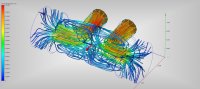
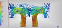
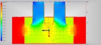
I ran a flow simulation on the air box. Senero, is CB360 @ 9,000 rpm, pulling 26 scfm per cylinder. It appears it is getting some scavanging between cylinders. Also has a good decrease in pressure in the air box before the velocity stacks.
Attachments


It's science bitches! Seriously, I dig the work you are putting into the airbox design.


