I know a few of you have been following my DIY Electronic Ignition thread over here, and so I figured I'd get a thread going on my other electronics project, a DIY Fuel Injection System.
I've collected most of the parts I'll need and I'm starting some basic code to get everything running.
Initial goal is multi-port injection (one injector per port), but non-sequential. The injectors will fire once per rotation of the engine, but will not be "correctly" timed to coincide with the opening of the intake valves. I'll save that for version two, perhaps.
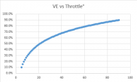
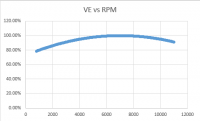
The method for fuel metering, to begin with, will be based purely on the engine RPMs and the position of the throttle (more on this in a bit). This is called an N-Alpha system. Based on the engine's current speed and the angle of the throttle plate, we can make reasonable a assumption about how much fuel is needed by the engine. The benefits to this approach are simplicity of programming, but you lose the ability to adapt as the fueling maps (more on this later, too) are fairly static and will need to be recreated for all performance modifications. N-Alpha is usually a poor choice for forced induction, as well.
So... where to start...
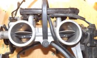
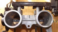
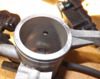
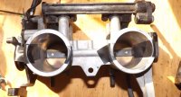
I decided to start with the hardware. I've picked up a set of EX650 (Kawasaki Ninja) fuel injected throttle bodies (TBs), a fuel pressure regulator, and a fuel pump. Fuel injectors rely on fuel whose pressure is 15 times (or more) than used by carbs. So in order to make the switch to EFI, we need a fuel pump capable of those pressures and a regulator to ensure the pressure remains steady. If pressures change while the bike is running then the fueling maps will no longer. Steady fuel pressure is a must.
The reason for the choice of the EX650 TBs is as follows:
*Same OD of the body on the exterior side - Air filters from my 360 are a perfect match to the EX650 bodies
*Injectors from the EX650 are good for 160cc/min of fuel (that's good enough to run my bike up to about 16,000 RPM before hitting 85% duty cycle on the injectors)
*The EX650 comes with a throttle position sensor as well as a MAP (manifold absolute pressure) sensor
*Not too many parallel twins these days, so I kind of had a limited selection
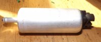
The fuel pump is a Delpha FE0088. It's a 12V electric pump that come on the Nissan Pulsar from '83 through to '86. I plan to run it at 40 PSI, but it's good for about twice that. It was originally meant to be run in-tank, but I'll be running it inline. Current draw at my required flow rate and PSI should be just under four amps.
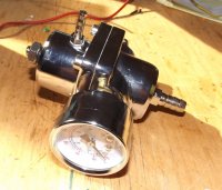
The fuel pressure regulator was an eBay China special. Hopefully it doesn't start spraying fuel all over my legs before going up in flames. It's meant to be a fit for most late model Honda cars, but as long as it holds a steady 40 PSI it can come from a lawn mower.
Now that the hardware is in place, it's time to work on the control system. I'll be using my trusty Arduino to read the sensors as well as control the fuel injection. As for the sensors, I'm primarily concerned with the Throttle Position Sensor (TPS) and the current speed of the engine. However, for tuning purposes, I'll also need to monitor the oxygen (O2) and MAP sensors.
Most of these sensors are analog, meaning an implementation in purely digital code can get a bit cumbersome. Luckily, the Arduino code library has some tricks in order to deal with this. I'll talk about those in a future post. In the mean time, the following voltage outputs can be expected from each of the sensors along with the meaning of those outputs:
(Wideband) O2 Sensor - Voltage differs depending on make and model of the sensor and so I'll be getting back to this in more detail in a future post
TPS - Voltages range for .2V and fully closed to 4.8V at fully open. The range is linear, so 2.5V is 50% throttle.
MAP - MAP sensors come in one bar, two bar, and three bar variants. I'll be using a two bar and the voltage range is from 0V at 1.3 PSI and 5V at 30.2 PSI. This sensor also operates linearly.
RPMS - This is our only digital sensor. I get one pulse every time the cam rotates and so we only need to count the the pulses and multiply by two in order to derive engine RPMs.
In order to get things up and going, the first order of business is to create a basic fueling map which will get the bike running. While I will be aiming at doing fueling with just the RPMs and throttle position, the MAP and O2 sensors will be needed for tuning. I'll be recording and constantly re-tuning the fueling maps based on sensor data. We can record readings from all of our sensors over time and after enough data has been gathered, we change the fueling map to account. Eventually, after we have filled in enough blanks, we can remove the O2 and MAP sensors and run with just the RPM sensor (which is needed for the ignition anyway) and the TPS. There is a pretty decent correlation between throttle position and pressure differential across the throttle body and the O2 sensor will fill in the rest.
I've collected most of the parts I'll need and I'm starting some basic code to get everything running.
Initial goal is multi-port injection (one injector per port), but non-sequential. The injectors will fire once per rotation of the engine, but will not be "correctly" timed to coincide with the opening of the intake valves. I'll save that for version two, perhaps.
The method for fuel metering, to begin with, will be based purely on the engine RPMs and the position of the throttle (more on this in a bit). This is called an N-Alpha system. Based on the engine's current speed and the angle of the throttle plate, we can make reasonable a assumption about how much fuel is needed by the engine. The benefits to this approach are simplicity of programming, but you lose the ability to adapt as the fueling maps (more on this later, too) are fairly static and will need to be recreated for all performance modifications. N-Alpha is usually a poor choice for forced induction, as well.
So... where to start...
I decided to start with the hardware. I've picked up a set of EX650 (Kawasaki Ninja) fuel injected throttle bodies (TBs), a fuel pressure regulator, and a fuel pump. Fuel injectors rely on fuel whose pressure is 15 times (or more) than used by carbs. So in order to make the switch to EFI, we need a fuel pump capable of those pressures and a regulator to ensure the pressure remains steady. If pressures change while the bike is running then the fueling maps will no longer. Steady fuel pressure is a must.
The reason for the choice of the EX650 TBs is as follows:
*Same OD of the body on the exterior side - Air filters from my 360 are a perfect match to the EX650 bodies
*Injectors from the EX650 are good for 160cc/min of fuel (that's good enough to run my bike up to about 16,000 RPM before hitting 85% duty cycle on the injectors)
*The EX650 comes with a throttle position sensor as well as a MAP (manifold absolute pressure) sensor
*Not too many parallel twins these days, so I kind of had a limited selection
The fuel pump is a Delpha FE0088. It's a 12V electric pump that come on the Nissan Pulsar from '83 through to '86. I plan to run it at 40 PSI, but it's good for about twice that. It was originally meant to be run in-tank, but I'll be running it inline. Current draw at my required flow rate and PSI should be just under four amps.
The fuel pressure regulator was an eBay China special. Hopefully it doesn't start spraying fuel all over my legs before going up in flames. It's meant to be a fit for most late model Honda cars, but as long as it holds a steady 40 PSI it can come from a lawn mower.
Now that the hardware is in place, it's time to work on the control system. I'll be using my trusty Arduino to read the sensors as well as control the fuel injection. As for the sensors, I'm primarily concerned with the Throttle Position Sensor (TPS) and the current speed of the engine. However, for tuning purposes, I'll also need to monitor the oxygen (O2) and MAP sensors.
Most of these sensors are analog, meaning an implementation in purely digital code can get a bit cumbersome. Luckily, the Arduino code library has some tricks in order to deal with this. I'll talk about those in a future post. In the mean time, the following voltage outputs can be expected from each of the sensors along with the meaning of those outputs:
(Wideband) O2 Sensor - Voltage differs depending on make and model of the sensor and so I'll be getting back to this in more detail in a future post
TPS - Voltages range for .2V and fully closed to 4.8V at fully open. The range is linear, so 2.5V is 50% throttle.
MAP - MAP sensors come in one bar, two bar, and three bar variants. I'll be using a two bar and the voltage range is from 0V at 1.3 PSI and 5V at 30.2 PSI. This sensor also operates linearly.
RPMS - This is our only digital sensor. I get one pulse every time the cam rotates and so we only need to count the the pulses and multiply by two in order to derive engine RPMs.
In order to get things up and going, the first order of business is to create a basic fueling map which will get the bike running. While I will be aiming at doing fueling with just the RPMs and throttle position, the MAP and O2 sensors will be needed for tuning. I'll be recording and constantly re-tuning the fueling maps based on sensor data. We can record readings from all of our sensors over time and after enough data has been gathered, we change the fueling map to account. Eventually, after we have filled in enough blanks, we can remove the O2 and MAP sensors and run with just the RPM sensor (which is needed for the ignition anyway) and the TPS. There is a pretty decent correlation between throttle position and pressure differential across the throttle body and the O2 sensor will fill in the rest.