Down under, an idiot and a 400F

You can get the vintage style crimped connectors through MCS:

http://www.mcsonline.com.au/

Although when I say "you", I mean you have to get them through a dealer as they only wholesale (most bike shops will have an MCS catalogue in their spares department).

The connectors are in Electrical (chapter 12).....but they only sell them in 100's.

You can download the catalogue online.
 
neevo said:
teazer those relays are 4 pin, do I need 5 pin to switch between 2 outputs?

Eg 2 pins for signal. 1 input, 2 outputs,

Correct. EB only show N.O. 4 contact types. You need one with an 87a terminal as well as 87. Those are very small relays and are smaller than the usual cubes.

If someone needs a picture, I have a couple of spare relays I can shoot a picture of with a ruler in the picture to scale it.
 
Very pleased with myself this evening. 1st draft of my wiring diagram is complete. A bit messy for a first draft and not even bothered with colours just yet but its all there:

55090A68-253B-4B7C-9E35-0166C2EDE0CC-1181-0000009A8143ADC4.jpg


Second draft will get the wiring lines tidied up (it's amazing how quickly you run out of space), place the components in their right spots relative to where they will be on the bike so that I can place earths in more appropriate places (they are a bit scattered at the moment), place connector blocks, wire in the illuminated ignition cutoff switch and colour the wires. Last piece to check is the wiring up of the instrument, going with an Acewell 4553 and think I've done it correctly, just need to make sure.

I do have a couple of questions though. My LED turn signals have 3 wires, what's going on there. Currently I've wired them up as if they had 2 but need to do them properly. And I assume I need another 5 pin relay to switch between rear light and brake light?

Any help is appreciated.
 
Jeeeez, looks very good! I've just found this thread and have been reading through every page since I too am working on a 1976 Honda Four and live in Sydney as well. So much of the information in your project thread can be translated to what I have to tackle in the future. Seeing your electrical diagram draft scares the living shit out of me (pardon the language), I hope I have what it takes when I get to this stage :p
 
I never try to do it all in one tidy diagram. I just have one for each circuit and leave it at that. Earth leads I work out when the wires and switches etc are all in place because then it's obvious. For example if say the tail light assembly is rubber mounted, I may choose to insert a long earth lead to take it back to the middle of the frame and I can't tell that from a diagram.

Check those LED lights. They may also include a running light.
 
findyourexit said:
Jeeeez, looks very good! I've just found this thread and have been reading through every page since I too am working on a 1976 Honda Four and live in Sydney as well.

Jesus! Good luck with ploughing your way through it ;)

There is a link to my blog in my signature that simplifies the thread down into the actions so you don't have to read all the chat too:

http://idiotsguidetocustom400f.blogspot.com.au

teazer said:
I never try to do it all in one tidy diagram. I just have one for each circuit and leave it at that. Earth leads I work out when the wires and switches etc are all in place because then it's obvious. For example if say the tail light assembly is rubber mounted, I may choose to insert a long earth lead to take it back to the middle of the frame and I can't tell that from a diagram.

Check those LED lights. They may also include a running light.

Cheers teazer as always. I became obvious which circuits were separate last night. I may have another go and separate 2 more for simplicity and run another live feed down the bike.

Good point re the earths too.

Did you see my question about needing another relay to switch the tail light? I assume I do to separate the running and brake light.

Will also put the LED turn signals onto the tester and battery to work out why the 3 wires.
 
Also what's the best solution for splicing wires together? On the original loom there are bullets with a 4 way female connector. I've got a main power feed with about 5-6 other feeds off it. May strip it down to 2 feeds however still need the ability to branch out a single wire into multiple wires.
 
neevo said:
Also what's the best solution for splicing wires together? On the original loom there are bullets with a 4 way female connector. I've got a main power feed with about 5-6 other feeds off it. May strip it down to 2 feeds however still need the ability to branch out a single wire into multiple wires.

You've probably noticed inside Jap wiring looms they use a simple non-insulated crimp connector. This is more than likely for speed on a production line, but also solder joins can fatigue over time with vibration (unlikely....but that would suck as a warranty recall....).

I've only ever needed to solder wires together - if they are taped inside a loom they are generally isolated and safe from separating.

Get one of those "3rd hand" stand things from Jaycar or Dick Smith. They've got 2 alligator clips so you can hold your wires together and have both hands free to solder. Strip the ends of the wires about 8mm, flow solder into each end, then put the ends together side by side and flow each end's solder together.

If you are doing a bunch of wires in a loom (or say...extending the wires on a switchblock / hardwiring an Acewell), stagger the joins so they are all at different points in the loom. That way your loom doesn't look like a snake that's swallowed a golf ball......and you won't need to use heatshrink on the individual joins because they will only be next to insulated wires ;)
 
neevo said:
There is a link to my blog in my signature that simplifies the thread down into the actions so you don't have to read all the chat too:
http://idiotsguidetocustom400f.blogspot.com.au

Hahaa cheers for the blog link mate, can't believe I missed it :eek:! Sub'd to thread anywho - too much good info to miss ;)
 
Lots of good points there Hillsy.

No relay for the tail light needed. If you use a PC8, take one large wire from battery to PC8 and that has a bus that allows for 8 individual powered & fused circuits.

Where you need to splice inside a loom, I twist and solder and wrap with tape. If you need to splice in say power to a gauge and power to say a switch, wrap the tiny one in the larger one and crimp them together into a connector. You can always use a touch of colder in necessary.

Another trick that is not recommended, but sometimes is necessary is to solder a small gauge wire to the outside of a connector pin and then push it back into the housing.
 
Is the PC8 a big thing? Had a look on ebay and couldn't pull up anything.

I'm happy to put a relay in, those 5 pins aren't huge.
 
I think I posted pictures on mine in a small cover on your other thread.

http://www.dotheton.com/forum/index.php?topic=44917.20

I made small aluminium cover to take the fuse panel, main switch and relays and painted it black so that it looks just like a frame brace/gusset. It's hidden in plain sight!

Or you may have enough space in the tunnel of the fuel tank to mount those parts.
 
Wiring diagram is complete! Including the Acewell and also taillight relay. Might fix some of the colours as I've got a bunch of live feeds in yellow which might be hard to trace at the front of the bike if anything goes wrong, but Honda runs a 5 way split of live black wires, so maybe its not a problem.

Still don't know how I'm going to get a single wire split into say 4 or more separate wires, but maybe something will come to me later down the track. The rear of the bike as a bulk negative post, but that should be easy as I can use loops and bolt multiple loops to the frame. Can't do that with live wires though unfortunately.

Ive got a PDF if anyone wants to double check it for me.

Thanks to everyone for their help, made a huge difference. Also thanks for making me go down this path, its not complete yet (still got to wire the bloody thing) but I'm feeling confident I can do that part and it will be easier running wires rather than finding space on a piece of paper ;)
 

Attachments

  • Custom Wiring Diagram CB400F.pdf
    115.8 KB · Views: 184
First of all - that looks good.


You need to ground the -ve from the battery to the engine and frame (that way you can also get a -ve anywhere on the bike by simply grounding). Not sure if you were going to do that.


Also, I don't think you need the relay to the brake lights or the clutch switch. And if you ground the horn switch through the bars you can get away with one wire there instead of two.
 
It's less wiring to use frame as ground but it's more efficient to run ground leads
Ed, how close are you to the fires?
I'm watching BBC World News, New South Wales seems to be having a real rough time, 40 degrees centigrade :eek: (about 106f, but, lots of trees, not desert)
 
crazypj said:
I'm watching BBC World News, New South Wales seems to be having a real rough time, 40 degrees centigrade :eek: (about 106f, but, lots of trees, not desert)

I live in Sydney, NSW and if it's any indication of how ridiculous it must be inland... it is 33 degrees celsius here... and it's 1:30am.... the peak I saw was 45 during the day...
 
Brake lights don't need a relay. They don't draw much power. What is the clutch lever switch and rectifier doing? I'd clean that out of there too. On the Fizzer it connects through a diode pack to the ECU to cut out the starter if it's in gear and the clutch is not pulled in. We don't need no stinkin diode pack and clutch switches.
 
hillsy
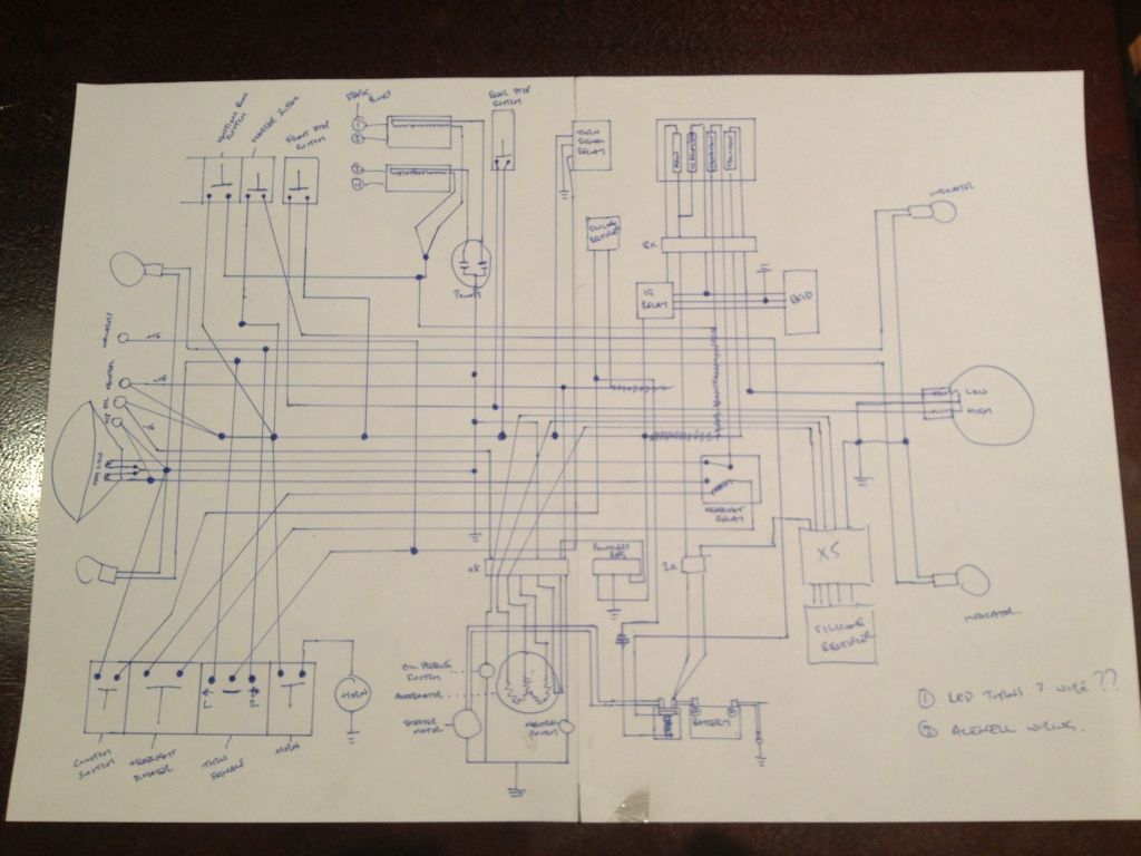
Thanks buddy, appreciate all your inputs! The -ve on the battery is grounded to the frame, its that long black wire, i tried to place things a bit where they would be on the bike so I could know where they would be wired a bit easier. That way I can have a ground point up front too and also where the coils are. I thought that would save on running -ve wires through the bike a bit.

Can you explain why I don't need a relay on the rear light / brake light? I was worried about burning it out (as it was quite an expensive LED cluster from Custom Dynamics). Previously I had the rear light wired into the ignition, so it came on whenever the ignition was live, and the brake light fed from the brake switches, but this meant it would have 2 live feeds into it when the brake light was activated. Hence why I used the relay to switch the power into the light.

crazypj
Using grounds via the frame for the most part. 1 at the rear, 1 at the coils and 1 up front in the headlight bucket (which actually grounds through the coils). Does that sound ok? I thought about running wires but thought I would try and keep it simple.

NSW is pretty damn hot at the moment, but luckily we've got 2 cooler days before it hits 42 degrees again! Im out western sydney which usually is a few degrees warmer than the city :eek: however yesterday the city got the worst of it. Damn weird having it 33 degress in the middle of the night though!

Fingers crossed they can get on top of the fires in the next couple of days!

teazer
See my comments on the relay for the brake light above in the hillsy response. I'm sure it wil work with a relay (and I've ordered 2 anyway), however if you think its redundant just let me know and I will simplify the wiring for the rear light. Just don't want to burn out the rear LED cluster.

The clutch lever is doing exactly what the original CB400F does. That rectifier is a diode pack I think (its got the arrow in it). Not sure how it works to cut out the starter motor if the bike is in gear and the clutch is not pulled in, but I left it there to be safe. Are they required for roadworthy? If so I will leave it in, if not I'm happy to get rid of the whole lot as I pull the clutch before hitting the starter button as a habit.
 
Back
Top Bottom