We noticed you are blocking ads. DO THE TON only works with community supporters. Most are active members of the site with small businesses. Please consider disabling your ad blocking tool and checking out the businesses that help keep our site up and free.
You are using an out of date browser. It may not display this or other websites correctly.
You should upgrade or use an alternative browser.
You should upgrade or use an alternative browser.
Yamaha SR250 - A clean standard build
- Thread starter JadusMotorcycleParts
- Start date
stroker crazy said:While there is a fad for extremely short pipes, a longer pipe works better overall.
People will follow fashion with short pipes and suffer mid-range power loss with (theoretical) stratospheric top-end revs, but some will prefer function over fad and go longer. Manufacturers usually have a reason behind the lengths they design for the bike.
Crazy
Thanks crazy, yeah that's the thing I guess If I'm going to try and sell these - do I follow a trend or the function? My original exhaust calculations for the SR engine, based on bore, stroke, cam specs, carb specs and a peak performance at 7000rpm (rather than the 9000rpm redline) actually gave a really nice midrange - starting to give good power from 3000 to 7000rpm. The calculations spat out an internal pipe diameter of 32mm (meaning using 35mm/ 1-3/8'' tube) and a total length of 28''. I had these estimations backed up by Pam from Powroll - his knowledge and suggestion was based on his experience with modifying the xt and tt250 (roughly the same engine) back in the late 80's for performance. He even actually suggested a total pipe length of 31''!
I think it would be best to stick with the original design, then people can choose to cut there pipe down themselves if they like
")
Knuckles said:Where do I sign up for the "tank drop" kit??? Yes please......
Cool! I will launching a webshop very shortly where you can place an order
JadusMotorcycleParts said:I rent a big space - its actually a converted laundry basement. Yeah, I had a really hard time finding a space too - especially in Malmö. Thats why I ended up in Arlöv haha. Nice you have a place now. Is your bike functional? It would be cool to meet up for a ride sometime
Hahaha, well as long as it's warm and has power and water it's awesome. A toilet isn't bad to have either
 My bike hasn't been on the road since 2008. Long story short, it broke down and I got pissed at it. I'm aiming at having it done by next summer before I move back home to Lund. Would be awesome to do some riding with another "small CC" bike!
Sent from my iPhone using Tapatalk
Eleganten said:Would be awesome to do some riding with another "small CC" bike!
Definitely man! Get in touch when you get down here. Haha 'small CC'. Its all relative I guess. When my Dad was riding bikes, a 250 was a medium to big size bike, in many countries it still is. Something with the Swedes - they just love BIG bikes!
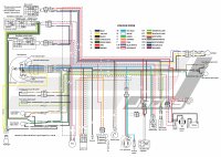
Re: Yamaha SR250 - High Quality, Detailed Colour Wire Diagram
I have been starting to modify some of the wiring harness to re-locate some things (horn, ignition, etc) plus installing the new speedo and a moto-Gadget M-Flash digital blinker relay (love these things!). In doing this, I decided I didn't like any of the wire diagrams I found available on the net and I didn't like looking at the one in the manual without colours. So I made my own. I actually started making this when I built my first SR a few years ago but ran out of time cos its so damn boring and time consuming. But today I finished it and it is all vectors so I can export it to whatever quality I like. Attached is a .jpeg and .pdf.
Free for all to download and use! 8) ;D
Attachments
JadusMotorcycleParts said:Definitely man! Get in touch when you get down here. Haha 'small CC'. Its all relative I guess. When my Dad was riding bikes, a 250 was a medium to big size bike, in many countries it still is. Something with the Swedes - they just love BIG bikes!
Yeah, we swedes seem to have a fondness for big bikes. I've always loved smaller bikes. Maybe because I was brought up on an Enfield India 500 with 22 HP. I lived in Australia a couple of years back and worked at a wrecking yard/Yamaha dealer and I really got fond of the small L-plate bikes like the zxr250, cbr250 and the 400cc equivalents. We got shitty bikes here in Sweden due to old insurance rules
 but we do have really good rules regarding customization of bikes.
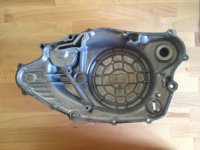
Do you know the measurements of the oil filter cover yet? Thought maybe Yamaha used the same for the sr4/500. In that case I have an idea to develop!
Sent from my iPhone using Tapatalk
Eleganten said:Yeah, we swedes seem to have a fondness for big bikes. I've always loved smaller bikes. Maybe because I was brought up on an Enfield India 500 with 22 HP. I lived in Australia a couple of years back and worked at a wrecking yard/Yamaha dealer and I really got fond of the small L-plate bikes like the zxr250, cbr250 and the 400cc equivalents. We got shitty bikes here in Sweden due to old insurance rulesbut we do have really good rules regarding customization of bikes.
Do you know the measurements of the oil filter cover yet? Thought maybe Yamaha used the same for the sr4/500. In that case I have an idea to develop!
Sounds like a cool experience you had in Australia. Yeah, I wondered why there are none (or very few) of the typical 1970s classic Japanese bikes here - like where are all the RD350s and RD400s (before the YPVS models) and where are all the CB350 twins and XS650 twins? They only come up once in a blue moon it seems.
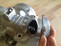
I have actually prototyped an oil cover already and it will fit SR400s, SR500s, XT500s, TT500s and the SRX600. I will get an aluminium prototype machined up and do some proper testing before I do anything further with that project
Something else I have put together that helps a lot when working on this bike and putting stuff back together. And even ordering replacement parts. Its a .pdf document with all the the exploded parts pictures and part numbers from www.boats.net Pretty good site to order a lot of original parts from.
Attachments
cosworth
Coast to Coast
Also if you look on the head, there is a Philips/JIS bolt that masks where the oil feed for the cam is. Oil under pressure rides up a cylinder head bolt hole the diverts near this drilled feed to the cam. The cam is then filled with oil and bleeds out to the intake and exhaust tappets. One more than the other with the flawed stock cam.
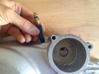
You can put a pressure sender or temp sensor where this bolt is if you are savvy. Safely tucked away from the grime and exposure under the sump.
You can put a pressure sender or temp sensor where this bolt is if you are savvy. Safely tucked away from the grime and exposure under the sump.
Thanks for the tip. I was aware of that check bolt but I dont really want to run the risk of messing anything up with the head. I have a spare clutch side engine cover anyways so I have decided to drill and tap into the oil passage there. Then I also get a more direct reading after the oil has passed through the filter - like, right after it.
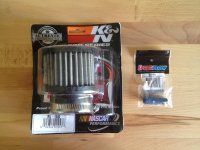
I got some mail today - an NPT fitting extension so I can run the standard sensors, plus a cool looking K&N filter. I am pretty over the whole 'pod' filter look and wanted a decent filter so decided it was worth it to fork out for this one rather than the no-brand/emgo junk (which I have used in the past myself btw!). So I got this more round style look and avoided any filter with chrome on it - for me, its not the place to try and be 'blingy'. So I chose the one with a rubber end instead
I got some mail today - an NPT fitting extension so I can run the standard sensors, plus a cool looking K&N filter. I am pretty over the whole 'pod' filter look and wanted a decent filter so decided it was worth it to fork out for this one rather than the no-brand/emgo junk (which I have used in the past myself btw!). So I got this more round style look and avoided any filter with chrome on it - for me, its not the place to try and be 'blingy'. So I chose the one with a rubber end instead
Attachments
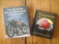
I have also really enjoyed reading these two books the past few weeks. I have gained a lot of inspiration from both of them. I felt a bit obliged to read the Husqvarna one because of living in Sweden and its a great story. The strange thing is, not that many Swedes even know Husqvarna made world famous motorcycles! For most of them Husqvarna means a small town and washing machines/appliances!
Attachments
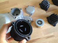
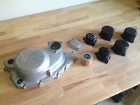
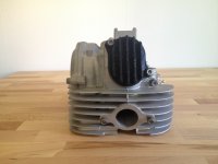
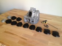
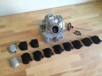
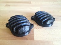
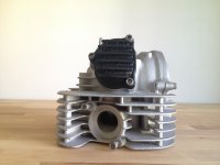
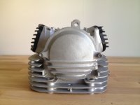
Been a bit quiet the past few days because I have been designing some concept valve covers and oil filter cover. If I was running this build as a project manager this would be getting waaaay off track. This was not at all on the cards in the beginning but I now see it as a fun product opportunity. I am not going to pretend I am an engineer in thermal dynamics or anything, but I have hopes that these might actually have a cooling effect. I have played with various fin heights, layouts, configurations etc. The latest oil filter cover concept holds an extra 100cc/mL of oil and has an increase of surface area of 300% over stock, so I hope it does something. Like I have said, everything will be tested properly. I just need to finalise a design and get some metal prototypes made
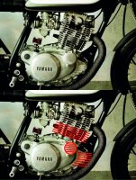
I have had some interesting design challenges when trying to integrate these covers into the design of the engine. I want them to look somewhat harmonious with the design - rather than some hack bolt on part. Trying to line up fins and match lines is not easy - see the red line diagram for example - do you line up the fins with the ones already on the crankcase cover? Or do you line them up with the cylinder fins? In the end I decided either way would be a compromise and that radial fins would not only avoid this visual clash, they actually offer greater surface area/cooling ability and might be easier to CNC.
I have had some interesting design challenges when trying to integrate these covers into the design of the engine. I want them to look somewhat harmonious with the design - rather than some hack bolt on part. Trying to line up fins and match lines is not easy - see the red line diagram for example - do you line up the fins with the ones already on the crankcase cover? Or do you line them up with the cylinder fins? In the end I decided either way would be a compromise and that radial fins would not only avoid this visual clash, they actually offer greater surface area/cooling ability and might be easier to CNC.
Attachments
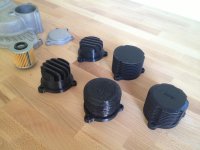
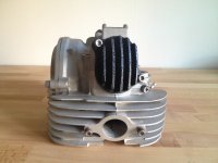
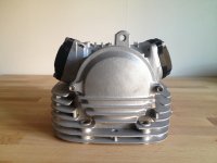
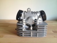
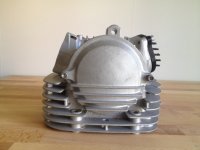
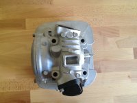
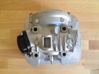
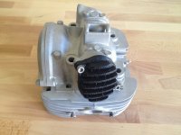
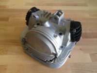
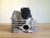
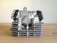
And here come some valve cover shots. First I had to get the dimensions exactly right - my digital vernier skills are only as good as my one squinted eye can handle. So I printed some basic patterns to them be able to make small adjustments in the 3D file to make them a perfect match. Then it was trying all sorts of fin angles and arrangements 8) Still haven't decided, but I am starting to think along the lines of the oil filter cover - don't try to match the existing lines, but rather make them vertical and in this way they don't clash but instead create their own visual element. This way you also end up with a Ducati-front-cyclinder-head-ish look haha One thing i did find/decide, was that fins over 10mm long just look goofy!
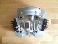
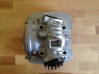
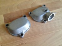
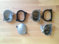
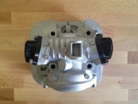
One thing that has been bothering me is the design of the exhaust valve cover. Why is it so different to the intake valve cover in terms of form? Ignoring the hole pattern of coarse. I cannot see any useful purpose for it to stick out like it does... My one and only theory is that the engineers at Yamaha tried to reduce 3D modeling time and tooling costs by making an insert exchange tool - where for the non-compression release valve covers, that insert is blanked off and you get a smooth surface, yet the same shape. Then when they wanted to run the tool to make the compression release version (for the XT and TT kick start versions), they put that insert in the tool and made that version. Thoughts?
One thing that has been bothering me is the design of the exhaust valve cover. Why is it so different to the intake valve cover in terms of form? Ignoring the hole pattern of coarse. I cannot see any useful purpose for it to stick out like it does... My one and only theory is that the engineers at Yamaha tried to reduce 3D modeling time and tooling costs by making an insert exchange tool - where for the non-compression release valve covers, that insert is blanked off and you get a smooth surface, yet the same shape. Then when they wanted to run the tool to make the compression release version (for the XT and TT kick start versions), they put that insert in the tool and made that version. Thoughts?
Attachments
-
 IMG_7375.JPG2.3 MB · Views: 380
 -
 IMG_7379.JPG2.2 MB · Views: 370
 -
 IMG_7371.JPG2.1 MB · Views: 370
 -
 IMG_7368.JPG2.1 MB · Views: 350
 -
 IMG_7366.JPG2.4 MB · Views: 364
 -
 IMG_7364.JPG2.6 MB · Views: 380
 -
 IMG_7361.JPG2.4 MB · Views: 364
 -
 IMG_7359.JPG2.2 MB · Views: 376
 -
 IMG_7358.JPG2.4 MB · Views: 367
 -
 IMG_7357.JPG2.5 MB · Views: 370
 -
 IMG_7352.JPG2.4 MB · Views: 372
 -
 IMG_7351.JPG2.4 MB · Views: 364
 -
 IMG_7350.jpg3.1 MB · Views: 351
FerousBastard
Active Member
Wow you have been busy! That printer is definitely getting put to good use. Personally I'd go with the oil filter cover design to the far right but just as a cover without the height of the cooling fins, that thing looks rad! Just a thought; Any cooling ability of the added surface area of the other designs would be negligible to the effort put into machining the part. Adding ports for an external oil cooler, now that's a different story.
For the valve covers I'd do something similar to the rad looking filter cover. The engine casings themselves have a lot of fins going on on their own, flowing all over the place as you've pointed out.
You said you are in Malmö right? I'm in Kolding, Danmark and am working on redesigning a LS650 savage; http://www.dotheton.com/forum/index.php?topic=66958 still working out the details though, but could be cool to exchange ideas sometime.
No idea of functionality (for that you would need to prototype and compare cylinder head temps) but I like the look of the horizontal valve covers! If the TT/XT exhaust valve covers fit the SR it might be a better manufacturing/sales plan to just make 1 exhaust cover and have a silicone plug for the SR use. As far as long fins vs short - if they were painted silver to match the engine, there would probably not be any visual difference between them, but (again) testing would tell if one was more effective than the other.
FerousBastard said:Wow you have been busy! That printer is definitely getting put to good use. Personally I'd go with the oil filter cover design to the far right but just as a cover without the height of the cooling fins, that thing looks rad! Just a thought; Any cooling ability of the added surface area of the other designs would be negligible to the effort put into machining the part. Adding ports for an external oil cooler, now that's a different story.
For the valve covers I'd do something similar to the rad looking filter cover. The engine casings themselves have a lot of fins going on on their own, flowing all over the place as you've pointed out.
You said you are in Malmö right? I'm in Kolding, Danmark and am working on redesigning a LS650 savage; http://www.dotheton.com/forum/index.php?topic=66958 still working out the details though, but could be cool to exchange ideas sometime.
Thanks man. Yeah, that printer is the best investment I ever made. After working as an industrial/product design engineer for 7 years i know that seeing physical prototypes is the best way to understand your design and the best way to make design/form decisions. I am definitely in agreement with you about the engine covers. I'll show you the valve covers I printed last night that I think I will go with - at least get them made in aluminium and test them anyway.
Yeah I'm in Malmö. Kolding ay, just checked it on the map. You studying there or commuting somewhere else? I actually saw your LS650 thread and really like what you're doing. I followed the Ryca dudes right from the beginning - way back when they were first written about in The Kneeslider in 2010 http://thekneeslider.com/ryca-cs-1-suzuki-s40-cafe-conversion/ But I feel your direction will offer something new. That first shot on your thread is so awesome! Do you know much about that particular bike?
Would be great to bounce some ideas man! I could also print some small stuff for you if/when you come to that. Congrats on the bike purchase btw, now your project can really get started!
zap2504 said:No idea of functionality (for that you would need to prototype and compare cylinder head temps) but I like the look of the horizontal valve covers! If the TT/XT exhaust valve covers fit the SR it might be a better manufacturing/sales plan to just make 1 exhaust cover and have a silicone plug for the SR use. As far as long fins vs short - if they were painted silver to match the engine, there would probably not be any visual difference between them, but (again) testing would tell if one was more effective than the other.
Thats an interesting idea with the exhaust valve cover! Do you have any idea why the SR one has the bulge in it? It doesnt look like a clearance issue for the tappet or rocker...
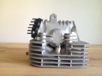
So you think the longer fins would be better?
Heres the vertical fins concept together on the head. I really do like the look of this but the horizontal fins, when angles correctly, look pretty nifty too. Thoughts?