Yamaha SR250 - A clean standard build

JadusMotorcycleParts said:
Got another one of them stuck crankcase bolts! Even with the impact driver it stripped the philips socket. But this time my standard solution worked - cut a slot in the head of the bolt with the die grinder using a thin cutting off disc. Then just use the big flat blade bit on the impact driver. Yus!

Also started installing the covers with new gaskets :D

Are you using a JIS phillips driver? you only get partial engagement with a standard phillips driver in a JIS screw.
 

Attachments

  • images.duckduckgo.com.jpg
    images.duckduckgo.com.jpg
    110.3 KB · Views: 987
doc_rot said:
Are you using a JIS phillips driver? you only get partial engagement with a standard phillips driver in a JIS screw.

Good Post, thanks.
 
doc_rot said:
Are you using a JIS phillips driver? you only get partial engagement with a standard phillips driver in a JIS screw.

Yeah awesome post! I didn't know about that at all. Just thought there were deep/pointy philips and shallower/fatter philips! But yeah, in that case, been using the JIS bit with the impact driver set. It seemed to fill the whole head screw head well. Despite this, it still seems that the heads of some of these screws are really soft - and haven't been touched for 30 something years ;)
 
Unless you specifically bought a JIS driver for your impact i would be surprised if it was JIS, it likely is a #3 standard phillips. Thats what my impact driver came with anyway. I didn't realize the Japanese had their own screw standard until a couple years ago after 15+ years of stripping screws on cars and bikes. They really do make a big difference. positive engagement. I had to special order a set of drivers because nobody sold them locally. They are not only shorter, but their footprint(?) is different. but the yeah the stock screws suck anyway, it just makes replacing them a lot easier with the right tool. The standard phillips is designed to cam out when overtightened.
 

Attachments

  • Philips-vs-JIS.jpg
    Philips-vs-JIS.jpg
    29 KB · Views: 989
doc_rot said:
Unless you specifically bought a JIS driver for your impact i would be surprised if it was JIS, it likely is a #3 standard phillips. Thats what my impact driver came with anyway. I didn't realize the Japanese had their own screw standard until a couple years ago after 15+ years of stripping screws on cars and bikes. They really do make a big difference. positive engagement. I had to special order a set of drivers because nobody sold them locally. They are not only shorter, but their footprint(?) is different. but the yeah the stock screws suck anyway, it just makes replacing them a lot easier with the right tool. The standard phillips is designed to cam out when overtightened.

You were right again. I just alternate between the No2 and No3 bits (as shown in the pic) depending on the size of the screw head. Although, looking at the stock screws, would you say they are JIS?
 

Attachments

  • IMG_8681.jpg
    IMG_8681.jpg
    1.2 MB · Views: 288
I decided to install the nipple for the oil temp/oil pressure sensor on the engine I am working on. This will save me having to swap between crankcase covers when doing the testing (cos I did this to the spare I had a swell). Once the testing phase is over, I will just blank it off with an NPT blanking plug - I have seen some nice ones on ebay :)

I was real careful when removing the aluminium plug and when drilling and tapping the hole not to get any filings into the oil galley. I stuffed a piece of aluminium covered in a clean rag into the slot as a stop for the bits. Seems to work well. Then vacuumed everything out with the shop vac and cleaned everywhere else with clean rags on the ends of spokes. Came up good enough. Anyone know if plumbers tape can be/is supposed to be use with oil line fittings? I presume so to form a seal, but does it hold up to the temps? Personally I have only used it to seal airlines in the past...
 

Attachments

  • IMG_8686.jpg
    IMG_8686.jpg
    1.1 MB · Views: 286
  • IMG_8685.jpg
    IMG_8685.jpg
    1.4 MB · Views: 271
  • IMG_8688.jpg
    IMG_8688.jpg
    1.3 MB · Views: 313
  • IMG_8684.jpg
    IMG_8684.jpg
    1.8 MB · Views: 272
  • IMG_8683.jpg
    IMG_8683.jpg
    1,018.4 KB · Views: 313
JadusMotorcycleParts said:
You were right again. I just alternate between the No2 and No3 bits (as shown in the pic) depending on the size of the screw head. Although, looking at the stock screws, would you say they are JIS?

Hmmm well they do appear to be rounded on the corners like a regular phillips but if they are stock screws they most certainly are JIS as any screw made in Japan will be. One way to identify a JIS screw is a little dimple on the head. Although this is not always present, just like how grade 8 bolts are not always marked correctly.
 

Attachments

  • images.duckduckgo.com.jpg
    images.duckduckgo.com.jpg
    70 KB · Views: 1,129
Grind 1/16th of an inch off of the tip of any #2 or #3 phillips. There's your JIS drivers.

I've used a standard #3 phillips approximately 247,961 times on the fasteners shown above and only the worst of the worst, bolts that should be replaced anyway, have ever given me issues.
 
DohcBikes said:
Grind 1/16th of an inch off of the tip of any #2 or #3 phillips. There's your JIS drivers.
+1 . . . not perfect, but gets you most of the way there, not so much on the #3 though - couple of taps with a hammer and you have a pretty good fit usually. One thing a lot of people don't seem to realize is that the most important part of working with these things is the capability of the operator. Simplistic as it sounds, when you use any screwdriver type tool, you have to split your effort into three separate areas. Pushing the driver towards the fastener to keep the bit engaged and rotating it to drive it in or take it out. More importantly, you have to grip the handle to accomplish both. And that is where the trouble is. When you have to put maximum effort into removing a screw, you divide up what strength you have among the three tasks. The tighter the screw, the tighter you have to grip the driver leaving less power available to turn and push in. Fix the grip problem with a piece of sticky back sandpaper like body shops use on a dual action sander. Wrap a piece around your driver handle and the high traction the sandpaper gives to your hand enables you to put greatly increased effort to pushing and turning. This is an old trick, and may sound lame, but it is unbelievably effective!

These guyshttp://www.vesseltools.com/hand-tools/screwdrivers/screwdriver-sets/view-all-products.html make pretty nice JIS drivers, and they have impact bits as well.
 
Lately I have relied on the newer Milwaukee M12 drill driver: with adjustable clutch and a jiz tip... If you start out at a lower setting unable to damage the fastener and just rattle it a while, then turn up the heat they seem to come loose almost effortlessly.

I do keep the cordless Dremel loaded up whith a cutting wheel to make a slot when the time comes though.

milwaukee-m12-drill.jpg
 
That's not bad - $10.16 for a set of replacement JIS impact driver bits from Vessel Tools!
Another trick (instead of the sand paper) is to use grip tape used for baseball bats or tennis rackets.
The Milwaukee M12 1/4" impact driver would be a better tool in this case than the drill/driver due to the higher instantaneous torque. FWIW most construction pros have switched to an impact driver to drive wood screws too, for the same reasons. I also have a (very well abused) M12 drill/driver and it has been VERY impressive in its operation - no floppy chuck bearings or loose motor brake.
 
I have the 1/4 impact also and use it even more, just not on stubborn JIS metrics, that "little" impact will suck the grippers right out of those soft screws in a jiffy ;)
 
doc_rot said:
Hmmm well they do appear to be rounded on the corners like a regular phillips but if they are stock screws they most certainly are JIS as any screw made in Japan will be. One way to identify a JIS screw is a little dimple on the head. Although this is not always present, just like how grade 8 bolts are not always marked correctly.

Aha, always wondered what the dot stamped on the heads of the screws meant! Just thought it was an OEM thing. The more you know!

DohcBikes said:
Grind 1/16th of an inch off of the tip of any #2 or #3 phillips. There's your JIS drivers.

Yep, done that too and it worked well enough. Although I will be looking for a set of JIS bits if I am going to be doing more work on these engines which is a hopefully ;)

jpmobius said:
One thing a lot of people don't seem to realize is that the most important part of working with these things is the capability of the operator.

Technique goes a long way yes. For me, it is one thing to be taught something and it is another to try, fail and learn yourself - the best way for your particular capabilities/dexterity haha

Tune-A-Fish said:
Lately I have relied on the newer Milwaukee M12 drill driver: with adjustable clutch and a jiz tip... If you start out at a lower setting unable to damage the fastener and just rattle it a while, then turn up the heat they seem to come loose almost effortlessly.

I do keep the cordless Dremel loaded up with a cutting wheel to make a slot when the time comes though.

milwaukee-m12-drill.jpg

Awesome tip. I need to invest in one of those. It will be especially useful for getting those stubborn fork/damper rod retaining bolts at the bottom of the fork legs!

Yep, the slot in the screw head has saved me many times!
 
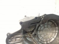
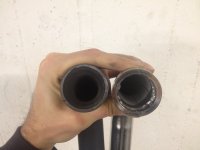
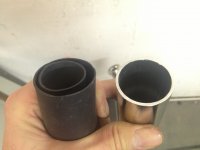
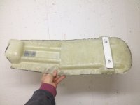
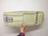
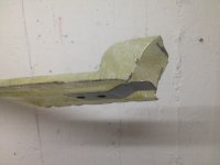
Snapped a couple of pics comparing the stock header to the header I designed. As you can see, a large difference.

A couple notes about the header... I ran 3 different exhaust header calculators to some up with the dimensions I went with. There was only one compromise, and that was the diameter. The internal diameter of the header is 31.4mm which puts peak power at 7500rpm with an ideal length of 590mm. To bring the power lower in the rpm range (say to 5000 - perhaps better for the street), the internal diameter would ideally be between 29-30mm with a length of 686mm. This would mean using 32mm/1-1/4'' (outside diameter) tubing. To me, this size tubing looks pathetic - just look at the stock Honda Transalp xl600v header. Looks lame (to me ;) ). So I decided to go up one size in tubing to 34mm/1-3/8'' tubing (outside diameter) for better looks and made the pipe longer (800mm) to compensate (longer for more torgue) - bringing the power back down to around 6000rpm. Of coarse the chosen silencer will play a role as well but these calculations were done with consideration to the header alone.

So, final dimension comparison:

Stock internal diameter: 26mm
Jadus internal diameter: 31.4mm

Stock length: 670mm
Jadus length: 800mm

There is also the idea that customers can cut down the size of the header pipe depending on their tastes and chosen silencer. The header comes with a split tube reducer to go over the end of the header and bring the diameter up to 38mm allowing the fitment of a wider range of silencers (using the usual reducers that come with them).

One more thing... Using tubing any thicker/larger in diameter would be for looks only (according to the calculations) - which would include any attempt to cut out the internal pipe on the stock header and just run the outer. This would be fruitless, unless you wanted the power to be strong from 9000 - 10000rpm, just outside of the SRs redline/capabilities.

Just to get a second opinion I contacted the guys at Poweroll and they backed up my ideas - they suggested that for a 250cc engine putting out 20-25hp, a header pipe with 1-3/8'' tubing and a length of 31'' would be ideal - which is 34mm outside diameter and 787mm length - not far off the pipe I designed ;D

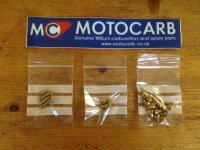
All this information could of coarse be completely useless unless properly backed up!!! Haha. When the bike is done, I will get some prices from a couple local shops with dynos and do some proper testing. I just ordered 20 genuine Mikuni jets for the carb for this testing purpose as I hope to give customers/anyone with an SR a good jetting baseline for a few different airfilter and header combinations. While at the dyno, I will do the temperature tests with the valve covers and the oil filter cover too.

Btw, anyone ever dynoed an SR250 or heard of anyone doing it? Plenty of videos on youtube of SR400s and 500s on dynoes but no 250s. Guess its never been worth it to anyone haha. I suspect the claimed 17-20hp (different models) would have been from the engine and not the wheel, meaning maybe 12-15hp at the rear wheel... We'll see ;D
 

Attachments

  • IMG_8656.JPG
    IMG_8656.JPG
    2 MB · Views: 270
  • IMG_8657.jpg
    IMG_8657.jpg
    1.8 MB · Views: 264
I found it! I thought I saw it somewhere... In one of the many articles I scanned I found a tester that actually put it on the dyno. It was tested by Stewart Car Company in Miranda, Sydney with Sun dynamometers (dont know if that is a company or a brand of dyno?) in 1981. The atmospheric correction factor was plus 0.9%. The max peak rear wheel power was 9.8kW - which is a tad over 13hp. So there you have it! See attached for yourself ;D Anyone else though? Thinking it might be a stretch to get the claimed 20hp now!
 

Attachments

  • SR250_1981DynoResults.pdf
    1.1 MB · Views: 200
Been experimenting with the seat base prototype tooling a bit but have moved onto the real tooling to get better results. The prototype tooling proved out the concept anyway. Now I have made one 'prototype' seat base to send to a customer in Thailand. He insisted he would sort the foam and the cover and I dont doubt it - imagine the tailor talent there. Looking forward to seeing what he does with it :D

The metal parts for mounting were made by hand and included M6 riv-nuts in the plate at the rear. In production these parts will be laser cut and bent up on a proper press brake in a proper machine shop haha. I think I will specify ally weld nuts too instead of rivnuts or pem nuts.
 

Attachments

  • IMG_8697.jpg
    IMG_8697.jpg
    1.3 MB · Views: 262
  • IMG_8698.jpg
    IMG_8698.jpg
    1.3 MB · Views: 248
  • IMG_8699.jpg
    IMG_8699.jpg
    1.3 MB · Views: 247
  • IMG_8700.jpg
    IMG_8700.jpg
    1.3 MB · Views: 272
  • IMG_8701.jpg
    IMG_8701.jpg
    1.1 MB · Views: 253
Just got sent some rad photos from a customer in Belgium - legend for sharing them with me. He was actually first out the gate to purchase a header 8) His freshly rebuilt and painted engine looks amazing. Then the header looks pretty clean too! Imho
 

Attachments

  • SR250_Exhaust.jpg
    SR250_Exhaust.jpg
    808.1 KB · Views: 253
  • SR250_Header.jpg
    SR250_Header.jpg
    860.1 KB · Views: 248
Go these in the mail today! Nice selection of genuine Mikuni jets for testing :) There are main jets, pilots and air jets.

I searched high and low to find a couple different variations of the needle jet and the jet needle as well but had no luck. Seems like with a lot of these factory standard Mikuni carbs, these jets were made especially. So what I am hoping is that the mid range will have enough adjustment in it on the spacing of the needle alone - raising it slightly each time to get the setting right. The needle on these carbs is a constant (single) taper anyway, so it would make sense that the more you raise or lower it, the more of less fuel you get. Would make things harder if it was a dual or triple taper needle!

Also, from all the searching I did, I found these guys (motocarb.co.uk) in the UK were the easiest to deal with, had the easiest to understand, extensive catalogue and pretty reasonable prices. I am sure there are good dealers like this on other continents too but this was good shipping for me and nice to be able to order in English rather than Swedish ;)
 

Attachments

  • SR250_CarbJets.jpeg
    SR250_CarbJets.jpeg
    472.4 KB · Views: 264
Postman came again :)

Love ordering parts from boats.net

Always have the parts, easy to follow explodeds and good shipping.
 

Attachments

  • IMG_8729.jpg
    IMG_8729.jpg
    2.9 MB · Views: 264
Slow progress with the engine... I started trying to mask everything up to be able to spray paint the barrel/jug but quickly realised how much of a nightmare it would be to get at all the surfaces. I would end up with such an uneven coat of paint - with build up on the edges of the fins and no paint between them almost. So I decided to buy some artist paint brushes and hand paint it! Two coats later...
 

Attachments

  • IMG_8728.JPG
    IMG_8728.JPG
    2.6 MB · Views: 267
Back
Top Bottom