Slow day here at work, so I'm currently theory-crafting on making my own voltage regulators for the KZ650B models. If you're unfamiliar with this bike, it uses a three phase electromagnetic alternator not dissimilar to that ones used in the four cylinder Hondas and the XS650. It does differ in one important way, however: It has no return path for the circuit for the exciter field coil. The Hondas and the XS use two wires, one out from the regulator and one back.
This is important because a lot of the combined units coming out of China (where 99% of these parts are made) are faulty. They're not setup to work in the same way as the stock units. In the original setup, the regulator controls your bike's voltage by controlling the power going to the electromagnet. Less power out of the regulator means a weaker electromagnet and less power being generated by your alternator. Many of the units coming from China are functional, but they don't work that same way. The units from China work more like the later DOHC Honda regulators: They always send full power to the electromagnet, but they vary the resistance on the return line. Higher resistance in a circuit means less power flowing through it, and the same goal is achieved by different means.
Anyway, going back to our poor Kawi. Because it has no return line, none of the modern regulator/rectifiers coming out of China are likely to work. There are a few small time businesses that can make these units and I know that Rick's still carries working R/Rs, but both are expensive and sometimes unavailable. So, why not make our own?
Up first, we need to break down the process of voltage regulation into discrete portions that we can handle somehow. Each portion then becomes it's own problem, which can be solved more easily, and the solution is then made up of those independent things, reassembled.
Here's the parts that I'm thinking of right now:
As with many electronic problems, my go to tool for this is my trusty Arduino.
Voltage Detection
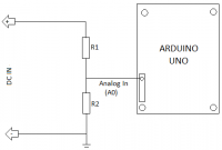
This particular problem is a fairly easy one. Arduino code has a built-in function called "analogRead()". This function returns a value from 0 to 1023, where 0 represents zero volts and 1023 is five volts. If anything more than five volts goes into the Arduino then all of the magic smoke escapes. So already we have a sub-problem to solve. Luckily this is a fairly common problem to have in the world of electronics and we can solve it using a couple of resistors to create what is known as a Voltage Divider.
A Voltage Divider does exactly what it sounds like. It takes an input voltage and divides it by a set amount into an output voltage. The formula for the Voltage Divider is Vout = Vin x (R2 / (R1 + R2)). So if R1 is 100,000Ω and R2 is 10,000Ω and our Vin is 15V, Vout is 1.36V. Definitely well within our allowable maximum of 5V. See first attached image for the schematic.
So every time we call the analogRead() function, we should now have a value for the current system voltage on the motorcycle that won't fry our electronics. Unfortunately, it's a bit difficult for us humans to translate that 0 to 1023 value into something meaningful, so a bit of math comes in handy. The actual voltage as detected by the Arduino can be calculated with the following bit of code:
int value = analogRead(analogPin);
float vOut = (value * 5.0) / 1024.0; //5.0 is the analogRead max and 1024.0 is the total range of possible values
float vIn = vout / (R2/(R1+R2));
At this point in the code, the variable, "vIn", is now equal to the system voltage of your bike at any given time. Voltage Detection is now a solved problem.
Field Coil Power
This problem is a bit trickier than the first, and it also has a series of sub-problems to solve. First, we need to figure out how to control power flow to the field coil. We can't run it directly through the Arduino because we come across the same problems we had in our first step: Too much voltage and too much current.
Fortunately, this is also a common occurrence when working with electronics and isn't too difficult to overcome. Your bike uses a low current button on the handlebars to activate a higher current solenoid for your starter motor and we can do a similar thing in electronics. Instead of being called a relay or solenoid, the device we're going to use is called a transistor. Specifically the Fairchild TIP125. The TIP125 was selected because it can handle up to 5 Amps at 60 Volts and it's also pretty darn cheap. Additionally, the TIP125 is a PNP resistor, used for high-side switching (as opposed to an NPN transitor which is used for low-side switching). The TIP125 comes in a TO-220 format (second attached picture) which means it has three pins in a set order and can (and should) be mounted to an appropriate heat sink. If we wanted to get fancy, we could have also used a MOSFET transistor such as IRF510 or IRF520.
The Base, Collector, and Emitter pins on the TIP125 all serve different purposes and we'll need all three. In this case, the collector is power from the bike, the emitter is the output to the field coil, and the base is how we turn our switch on and off. In this case, because we're using a PNP transistor, the switch is activated when the base pin is grounded and the switch is opened (turned off) when the base pin is not grounded.
Unfortunately, activating a transistor isn't as easy as it sounds. Transistors are activated when their base pin becomes "saturated". Despite how we often think of electronics as a binary system of zeros and ones, a zero or a one is actually a little fuzzy. For instance, in the digital world of five volt signalling systems, anything from zero volts all the way up to about 1.5V is still considered a zero and anything above three voltage is considered a one. But that's just for input voltages. Output voltages have their own scale of what's acceptable. But I digress... The point I'm getting to is that in order to activate the base pin and ground it out, we can't go through the Arduino because we run into voltage problems again. The Arduino can't handle the necessary power needed to actually saturate the transistor gate and then activate the switching property we're after.
Additionally, a PNP transistor needs a resistor on the base pin to avoid pulling the full power of the source through the base and still cooking whatever you're using for the triggering process. To calculate the required resistance, we need to know three values: The nominal voltage we expect from our application, the maximum current we're going to allow through the transistor, and the DC Current Gain of the transistor (usually abbreviated as HFE and listed on the database for the transistor).
The formula for calculating the value of R1 is: Supply Voltage / (Maximum Current / (HFE * 1.3)). In this case we have R1 = 12 / (5 / (1000 * 1.3)) or 3120 Ohms. 3300Ω would be a good match. An optional second resistor is also used in this circuit to ensure that some voltage is always flowing and proving a minimum signal. A voltage level of zero can sometimes go negative and cause weird happenings so we toss in another resistor to allow just a trickle of power through. As we discussed earlier, just a little power is still considered to be "off", so we're good. R2 can just be 10 times the value of R1.
Anyway... back to the process of switching our PNP transistor. Because the Arduino isn't up to the task of handling the current and power flowing through the base pin of the PNP transistor, we're back to using second transistor to active the first transistor. In this case, we're going to be using the low-side switching property of an NPN transistor. The reason for the use of an NPN transistor is that it takes very little power to activate it. In this case, it's a transistor we can trigger directly from the Arduino. I'm going to stick with the TIP family because I have a few laying around, but just about any NPN transistor would work for this application. TIP120 here we come.
For this setup, the collector is going to be connected to the output base pin from the TIP125. The emitter on our TIP120 goes to ground, and the base pin goes to the Arduino. Unlike the TIP125, the TIP20 is switched when it received power on the base pin, rather than when the base pin is grounded. When the Arduino send the signal to the base pin on the TIP120, the circuit between the 120's collector and emitter is completed, allowing a pathway to ground from the base pin on the 125. With the base pin on the 125 effectively grounded, the (nominal) 12V power source from the bike can flow through the 125's collector pin, out the emitter pin, and to our field coil.
So to wrap things up, we use the Arduino to control an NPN transistor because these types of transistors are very forgiving when it comes to direct control from a digital source. The NPN is used for low side switching though, which won't work for us because we want the current to flow to the field coil and we don't want to throttle things on the return trip, we want to control the output to the field coil. Additionally, we can't hook up a PNP transistor directly to the Arduino for the amount of current we want to switch, so the PNP gets controlled by the NPN. This is like using a very small switch to control a relay, which in turn, controls another relay, which controls the actual source of power.
Problem solved.
Field Coil Power Modulation
Now comes the fun part. Simply sending full power through to the field coil all of the time will not result in any level of voltage regulation. We need to send just the right amount of power through to the field coil so that the alternator is producing the correct amount of power for any given situation.
One of the interesting points of digital electronics it is entirely possible to simulate an analog value by turning a switch on and off at a high enough frequency. For instance, if we take a 12V power source and switch it on and off several thousand times per second (in equal on/off intervals), your voltmeter will read it as 6V. W're going to do the same thing with our field coil.
On the Arduino, several of the output pins support what is known as Pulse Width Modulation. PWM is used to simulate analog outputs such as brightness of lights or the speed of a motor. And just like we have an analogRead() function available to us with the Arduino, we also have an analogWrite() function. The difference is that instead of 0 to 1023 value range, analogWrite() uses 0 to 254. As before, 0 is fully off and 254 is fully on. The values in between are "partly on". See attached image for the expected output.
Code Complete
OK... so lets make it all happen. Time to write some code.
const int PIN_VIN = A0; //pin A0 is the same as pin 14 for input
const int PIN_PWM = 3; //using pin three for PWM control
const float R1 = 100000.0; //value of resistor one, make it a float for easier math
const float R2 = 10000.0; //value of resistor two, make it a float for easier math
const int MS_DELAY = 10; //how long to wait, in milliseconds, between readings
const float TARGET_VOLTAGE = 14.2; //target input voltage
const int MAX_INDEX = 254; //maximum allowable value for the PWM index
int pwmIndex = MAX_INDEX; //setup the index value for the PWM to start at the max value
//runs once on startup
void setup() {
pinMode(PIN_PWM, OUTPUT); //setup the PWM pin for output mode, no need to setup input pins
}
//runs continuously
void loop() {
int value = analogRead(analogPin); //read the current value of the input pin
float vOut = (value * 5.0) / 1024.0; //5.0 is the analogRead max and 1024.0 is the total range of possible values
float vIn = vOut / (R2/(R1+R2)); //calculate the actual system voltage
if(vIn < TARGET_VOLTAGE && pwmIndex < MAX_INDEX) //if current voltage is less than the target voltage and we're not yet running at 100% output, turn it up
{
pwmIndex++; //pwm index + 1
}
else if (vIn > TARGET_VOLTAGE && pwmIndex > 0) //if current voltage is greater than the target voltage and we're not yet running at 0% output, turn it down
{
pwmIndex--; //pwm index -1
}
analogWrite(PIN_PWM, pwmIndex); //set the PWM value
delay(MS_DELAY); //wait a for a bit for the real world to catch up, then start over
}
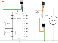
The Full Schematic
The final hardware diagram would look something like the last image attached to this post. Note the addition of the LM7805 voltage regulator to ensure the Arduino is seeing a steady 5V as it's input power, instead of the fluctuating and nominal 12V of the bike's system.
Conclusion
So yeah... I haven't actually tried any of this stuff yet, so use at your own risk. I'll probably cobble something together in the next year or so and see how things pan out. As always, real world examples beat out clever words on paper.
As a corollary and as a fun experiment, I'm willing to offer up a free LED headlight to anyone who can adapt this schematic and code to work for a permanent magnet alternator. I've done my version already, but I'd be interested to see what anyone else comes up with. Hint: PM regulators work by either limiting the voltage and current entering the system (Series type regulator) or bleeding off the excess voltage and current to ground (Shunt type regulator). Good luck.")
This is important because a lot of the combined units coming out of China (where 99% of these parts are made) are faulty. They're not setup to work in the same way as the stock units. In the original setup, the regulator controls your bike's voltage by controlling the power going to the electromagnet. Less power out of the regulator means a weaker electromagnet and less power being generated by your alternator. Many of the units coming from China are functional, but they don't work that same way. The units from China work more like the later DOHC Honda regulators: They always send full power to the electromagnet, but they vary the resistance on the return line. Higher resistance in a circuit means less power flowing through it, and the same goal is achieved by different means.
Anyway, going back to our poor Kawi. Because it has no return line, none of the modern regulator/rectifiers coming out of China are likely to work. There are a few small time businesses that can make these units and I know that Rick's still carries working R/Rs, but both are expensive and sometimes unavailable. So, why not make our own?
Up first, we need to break down the process of voltage regulation into discrete portions that we can handle somehow. Each portion then becomes it's own problem, which can be solved more easily, and the solution is then made up of those independent things, reassembled.
Here's the parts that I'm thinking of right now:
- Voltage Detection - We need to know the current voltage in the system at any given time
- Field Coil Power - We need to turn power on and off to the field coil
- Field Coil Power Modulation - Power to the field coil needs to be turned on and off at an appropriate rate to hold our system voltage "steady"
As with many electronic problems, my go to tool for this is my trusty Arduino.
Voltage Detection
This particular problem is a fairly easy one. Arduino code has a built-in function called "analogRead()". This function returns a value from 0 to 1023, where 0 represents zero volts and 1023 is five volts. If anything more than five volts goes into the Arduino then all of the magic smoke escapes. So already we have a sub-problem to solve. Luckily this is a fairly common problem to have in the world of electronics and we can solve it using a couple of resistors to create what is known as a Voltage Divider.
A Voltage Divider does exactly what it sounds like. It takes an input voltage and divides it by a set amount into an output voltage. The formula for the Voltage Divider is Vout = Vin x (R2 / (R1 + R2)). So if R1 is 100,000Ω and R2 is 10,000Ω and our Vin is 15V, Vout is 1.36V. Definitely well within our allowable maximum of 5V. See first attached image for the schematic.
So every time we call the analogRead() function, we should now have a value for the current system voltage on the motorcycle that won't fry our electronics. Unfortunately, it's a bit difficult for us humans to translate that 0 to 1023 value into something meaningful, so a bit of math comes in handy. The actual voltage as detected by the Arduino can be calculated with the following bit of code:
int value = analogRead(analogPin);
float vOut = (value * 5.0) / 1024.0; //5.0 is the analogRead max and 1024.0 is the total range of possible values
float vIn = vout / (R2/(R1+R2));
At this point in the code, the variable, "vIn", is now equal to the system voltage of your bike at any given time. Voltage Detection is now a solved problem.
Field Coil Power
This problem is a bit trickier than the first, and it also has a series of sub-problems to solve. First, we need to figure out how to control power flow to the field coil. We can't run it directly through the Arduino because we come across the same problems we had in our first step: Too much voltage and too much current.
Fortunately, this is also a common occurrence when working with electronics and isn't too difficult to overcome. Your bike uses a low current button on the handlebars to activate a higher current solenoid for your starter motor and we can do a similar thing in electronics. Instead of being called a relay or solenoid, the device we're going to use is called a transistor. Specifically the Fairchild TIP125. The TIP125 was selected because it can handle up to 5 Amps at 60 Volts and it's also pretty darn cheap. Additionally, the TIP125 is a PNP resistor, used for high-side switching (as opposed to an NPN transitor which is used for low-side switching). The TIP125 comes in a TO-220 format (second attached picture) which means it has three pins in a set order and can (and should) be mounted to an appropriate heat sink. If we wanted to get fancy, we could have also used a MOSFET transistor such as IRF510 or IRF520.
The Base, Collector, and Emitter pins on the TIP125 all serve different purposes and we'll need all three. In this case, the collector is power from the bike, the emitter is the output to the field coil, and the base is how we turn our switch on and off. In this case, because we're using a PNP transistor, the switch is activated when the base pin is grounded and the switch is opened (turned off) when the base pin is not grounded.
Unfortunately, activating a transistor isn't as easy as it sounds. Transistors are activated when their base pin becomes "saturated". Despite how we often think of electronics as a binary system of zeros and ones, a zero or a one is actually a little fuzzy. For instance, in the digital world of five volt signalling systems, anything from zero volts all the way up to about 1.5V is still considered a zero and anything above three voltage is considered a one. But that's just for input voltages. Output voltages have their own scale of what's acceptable. But I digress... The point I'm getting to is that in order to activate the base pin and ground it out, we can't go through the Arduino because we run into voltage problems again. The Arduino can't handle the necessary power needed to actually saturate the transistor gate and then activate the switching property we're after.
Additionally, a PNP transistor needs a resistor on the base pin to avoid pulling the full power of the source through the base and still cooking whatever you're using for the triggering process. To calculate the required resistance, we need to know three values: The nominal voltage we expect from our application, the maximum current we're going to allow through the transistor, and the DC Current Gain of the transistor (usually abbreviated as HFE and listed on the database for the transistor).
The formula for calculating the value of R1 is: Supply Voltage / (Maximum Current / (HFE * 1.3)). In this case we have R1 = 12 / (5 / (1000 * 1.3)) or 3120 Ohms. 3300Ω would be a good match. An optional second resistor is also used in this circuit to ensure that some voltage is always flowing and proving a minimum signal. A voltage level of zero can sometimes go negative and cause weird happenings so we toss in another resistor to allow just a trickle of power through. As we discussed earlier, just a little power is still considered to be "off", so we're good. R2 can just be 10 times the value of R1.
Anyway... back to the process of switching our PNP transistor. Because the Arduino isn't up to the task of handling the current and power flowing through the base pin of the PNP transistor, we're back to using second transistor to active the first transistor. In this case, we're going to be using the low-side switching property of an NPN transistor. The reason for the use of an NPN transistor is that it takes very little power to activate it. In this case, it's a transistor we can trigger directly from the Arduino. I'm going to stick with the TIP family because I have a few laying around, but just about any NPN transistor would work for this application. TIP120 here we come.
For this setup, the collector is going to be connected to the output base pin from the TIP125. The emitter on our TIP120 goes to ground, and the base pin goes to the Arduino. Unlike the TIP125, the TIP20 is switched when it received power on the base pin, rather than when the base pin is grounded. When the Arduino send the signal to the base pin on the TIP120, the circuit between the 120's collector and emitter is completed, allowing a pathway to ground from the base pin on the 125. With the base pin on the 125 effectively grounded, the (nominal) 12V power source from the bike can flow through the 125's collector pin, out the emitter pin, and to our field coil.
So to wrap things up, we use the Arduino to control an NPN transistor because these types of transistors are very forgiving when it comes to direct control from a digital source. The NPN is used for low side switching though, which won't work for us because we want the current to flow to the field coil and we don't want to throttle things on the return trip, we want to control the output to the field coil. Additionally, we can't hook up a PNP transistor directly to the Arduino for the amount of current we want to switch, so the PNP gets controlled by the NPN. This is like using a very small switch to control a relay, which in turn, controls another relay, which controls the actual source of power.
Problem solved.
Field Coil Power Modulation
Now comes the fun part. Simply sending full power through to the field coil all of the time will not result in any level of voltage regulation. We need to send just the right amount of power through to the field coil so that the alternator is producing the correct amount of power for any given situation.
One of the interesting points of digital electronics it is entirely possible to simulate an analog value by turning a switch on and off at a high enough frequency. For instance, if we take a 12V power source and switch it on and off several thousand times per second (in equal on/off intervals), your voltmeter will read it as 6V. W're going to do the same thing with our field coil.
On the Arduino, several of the output pins support what is known as Pulse Width Modulation. PWM is used to simulate analog outputs such as brightness of lights or the speed of a motor. And just like we have an analogRead() function available to us with the Arduino, we also have an analogWrite() function. The difference is that instead of 0 to 1023 value range, analogWrite() uses 0 to 254. As before, 0 is fully off and 254 is fully on. The values in between are "partly on". See attached image for the expected output.
Code Complete
OK... so lets make it all happen. Time to write some code.
const int PIN_VIN = A0; //pin A0 is the same as pin 14 for input
const int PIN_PWM = 3; //using pin three for PWM control
const float R1 = 100000.0; //value of resistor one, make it a float for easier math
const float R2 = 10000.0; //value of resistor two, make it a float for easier math
const int MS_DELAY = 10; //how long to wait, in milliseconds, between readings
const float TARGET_VOLTAGE = 14.2; //target input voltage
const int MAX_INDEX = 254; //maximum allowable value for the PWM index
int pwmIndex = MAX_INDEX; //setup the index value for the PWM to start at the max value
//runs once on startup
void setup() {
pinMode(PIN_PWM, OUTPUT); //setup the PWM pin for output mode, no need to setup input pins
}
//runs continuously
void loop() {
int value = analogRead(analogPin); //read the current value of the input pin
float vOut = (value * 5.0) / 1024.0; //5.0 is the analogRead max and 1024.0 is the total range of possible values
float vIn = vOut / (R2/(R1+R2)); //calculate the actual system voltage
if(vIn < TARGET_VOLTAGE && pwmIndex < MAX_INDEX) //if current voltage is less than the target voltage and we're not yet running at 100% output, turn it up
{
pwmIndex++; //pwm index + 1
}
else if (vIn > TARGET_VOLTAGE && pwmIndex > 0) //if current voltage is greater than the target voltage and we're not yet running at 0% output, turn it down
{
pwmIndex--; //pwm index -1
}
analogWrite(PIN_PWM, pwmIndex); //set the PWM value
delay(MS_DELAY); //wait a for a bit for the real world to catch up, then start over
}
The Full Schematic
The final hardware diagram would look something like the last image attached to this post. Note the addition of the LM7805 voltage regulator to ensure the Arduino is seeing a steady 5V as it's input power, instead of the fluctuating and nominal 12V of the bike's system.
Conclusion
So yeah... I haven't actually tried any of this stuff yet, so use at your own risk. I'll probably cobble something together in the next year or so and see how things pan out. As always, real world examples beat out clever words on paper.
As a corollary and as a fun experiment, I'm willing to offer up a free LED headlight to anyone who can adapt this schematic and code to work for a permanent magnet alternator. I've done my version already, but I'd be interested to see what anyone else comes up with. Hint: PM regulators work by either limiting the voltage and current entering the system (Series type regulator) or bleeding off the excess voltage and current to ground (Shunt type regulator). Good luck.