zachattach
Project Doldrums
I put the following together in response to a question that came in by email in regards to wiring and electronics. I believe that many or most all of you on this forum already know this stuff, but perhaps it will be a helpful comprehensive point of reference for some.
Regarding the electronics, here are some things you need and need to know:
Basic & Essential Information
1. Start by reading this excellent post to get a better understanding of motorcycle wiring and the possible solutions out there: http://www.bikeexif.com/motorcycle-wiring
Guzzi specific: Maybe have a look at this to get a better sense of the wiring sizes, etc. that you will find on a Guzzi: http://www.s3750motoguzzi.co.uk/rewiring/rewiring.html
2. Find a copy of your wiring diagram!
Guzzi specific: Many wiring diagrams available here: http://www.thisoldtractor.com/guzzi007/sportissimo.html I found that the colors may not match up 1-to-1 with a given bike's wiring harness, but the layout of one of these is probably 90+% correct. I attached the wiring diagram that I found best for my bike to this email.
Wiring and Terminals
If you are just going to use the existing wiring harness and switch gear, chance are you will need new terminals. If you are going to make a custom harness, then you will need wire too. These can be sourced from the following places:
Terminals:
http://www.vintageconnections.com/
http://www.cycleterminal.com/flag-terminals.html
ships to Europe only: kojaycat
Wire:
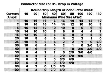
As far as I can tell, in the US it is easiest just to get to your local car parts store. Worse, once there you will have to make sense of the insane AWG system. That is right, here in the US this formula explains the cross sectional surface area relationship between, say, 12 and 14 guage wire:

God help us...
If you are on the metric system, well, it all just make sense (surprise?)
If you are in Europe you are in luck because you can buy an amazing selection of cut to length wire from this company: kojaycat
Why they wont ship to the US when I made it clear that I would pay virtually any shipping price they wanted? I don't know. That is why I tried to avoid giving them an active hyperlink.
Also, if you are going the mUnit route you can just buy one of the wiring kits directly from Motogadget (Non-US ordering) or from one of these two places:
http://revivalcycles.com/collections/for-your-ride-bestsellers/products/revival-cycles-deluxe-cable-kit
https://spieglerusa.com/gauges-instruments/electrics/control-box/m-unit-cable-kit.htm
Crimping Tool
You will also need a crimping tool, these are available from the terminal vendors. This is where I bought mine. I am not in love with it because the axial movement frequently leads to malformed crimps, but it got the job done.
Lithium Ion Batteries
I believe that most of the conventional Lithium motorcycle batteries available are just plastic packages containing multiples of 4 A 123 LifePO4 battery cells, or the same cell by some other manufacture. I don't recall the brands, but I have found one or two high dollar Li batteries that include some special power optimization circuitry integrated into the battery. While these batteries are seem to be 2x the cost of a Ballistic (link to this later) I have no doubt that this does in fact serve to extend the life of the Li cells in the batteries. The cells seem to be pretty fickle about the current that they like to charge off of, and I suspect that the general charging circuit on a motorcycle isn't optimal (I would love to go deeper into this at some point).
So, here are your options if you want an Li battery.
1. Buy one from Ballistic or another manufacturer: https://www.ballisticparts.com/category.php?cPath=141 The batteries will come in various multiples of 4 cells (each cell is 3.2 v, so 4 in series gives you 12.8 v, which gets you above the requisite threshold for running the 12v electrical system).
Small Twin Guzzi Specific: You will probably want an 8 cells, and oh btw, these bikes might actually necessitate that giant stock Bosh starter.
2. Make a Li battery! The A123 cells can be purchased through ebay. Buy some multiple of 4 of these, solder them together into packs of 4 cells in series, and then conjoin these packs somehow. Here are some youtube instructions: --https://www.youtube.com/watch?v=UTDctiyUa9E--
Note on my setup: I elected to use option 2 because it gave me some flexibility on shape. Rather than arranging the cells side by side, I arranged them literally in series. 2 "packs" of four cells wired together with heavy gauge battery cable should effectively give me the equivalent cranking power and power reserves as an 8 cell Ballistic battery.
If you go the Li battery route, you should also get an Li specific charger: http://www.ballisticparts.com/product_info.php?cPath=143&products_id=437
You can charge the batteries with a conventional charger, but I suspect it ruins the cells quickly. In a pinch do it, and don't fret. I observed a ballistic tolerate heavy amounts of such abuse over the course of a year (thanks to predictable CX500 stater issues). The performance of the battery was clearly diminished at the end of this, but it still worked.
The Electrical Components
Your electrical system is also going to be comprised by a number of pieces that look like they harken back to the days of vacuum tubes and other primitive electronics, and well, they do.
Who knows which of these pieces still work, and which ones do not. My understanding is that if they work, they work. No need to fix.
Guzzi Specific: If these parts do not work, you can always source replacement parts form one of these companies:
http://www.mgcycle.com/index.php?main_page=index&cPath=37_161
http://www.stein-dinse.biz/Moto-Guzzi/Electrical-Ignition/Regulator-Rectifier:::1_39_197.html
You could also replace your regulator and rectifier with newer technology and pick up one of these:http://www.ebay.com/itm/81-Moto-Guzzi-V50-MK2-Electrosport-Industries-Regulator-Rectifier-ESR450-/371109355208
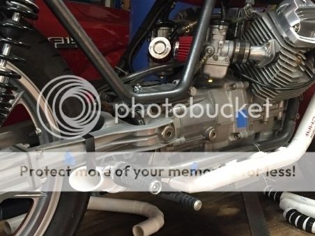
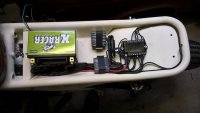
Note on my setup: Since I was going to be fabricating mounts around all of these pieces, I wanted to start with components I could trust. Thus I elected to upgrade to a contemporary rectifier. This is now mounted on the bottom side of the "back bone" frame rail that runs under the tank. Given that I have removed the factory air box, it should catch nice airflow in its current position. I also eliminated the remainder of the stock electrical components (flasher relay and some other relay), by installing an mUnit (more on this later). mUinit or no mUnit, you will still require a fuse box, and I elected to keep the stock one for no reason besides the fact that I thought it looked cool.
Switch Gear
Guzzi Specific: The stock switch gear is probably fine. You can use this, or swap in other switch gear that will tolerate running a full electrical load. Swapping in mid 70's honda switch gear or something would allow you to ditch the cheep Guzzi switch gear in exchange for cast aluminum options. This might be of appeal.
Given the way the conventional electronic system & wiring harness is set up, if you want to switch to minimalist-style switch gear and/or reduce the bulky ropes of wire running up to the handle bars, you will have to device a way for the switch gear to no longer be running full electrical load, but rather for it to simply be controlling circuits that are running the full load. If you have a basic foundation in electronics you can probably easily fabricate a solution to this...if you don't, you buy an mUnit.
The mUnit
Enter the mUnit:http://motogadget.com/en/electrics/electronic-control-box-m-unit/m-unit-digit-tastersteuerung-u-sicherung.html
Sources:
http://motogadget.com/de/ (EU ordering only)
https://spieglerusa.com/ (US ordering)
http://revivalcycles.com/ (US ordering)
Is an mUnit a need? No...it is a want...but it is so sexy, and in reality it does make doing a custom electronic setup so pain free that you are going to want to try to justify to yourself that it is a need.
Here is why you might give yourself permission to buy one:
1. It makes designing a custom wiring harness a cinch.
2. If a circuit goes down: (a.) the mUnit will indicate which circuit has the short and (b.) you don't need to replace a fuse.
3. The switch gear is no longer managing full electrical loads. The full loads are managed exclusively in the circuits managed by and running through the mUnit. This means that you can can run filament thin wires up to the switch gear on the bars and use minimalist switch gear like motogadget's exorbitantly expensive m Switch family (http://motogadget.com/en/am-lenker/m-switch-3/m-switch.html)
4. It replaces the relays that were just going to fail on you at some point anyways (so you will get your money back in ~400 years of riding)
5. It does nifty brake light stuff
6. It provides an alarm function
And lastly, you might just be honest with yourself and acknowledge that you are buying it because it is impossibly cool...
Concluding Thoughts
I hope some of you out there find this helpful. I took hours of googling and a number of phone calls to all of this out on my end. Even with this info there will still be problems to solve, but all of the foundational information you need to approach that should be contained here in. Happy wiring!
Oh, and an unfortunate lot of us might benefit from this.
Regarding the electronics, here are some things you need and need to know:
Basic & Essential Information
1. Start by reading this excellent post to get a better understanding of motorcycle wiring and the possible solutions out there: http://www.bikeexif.com/motorcycle-wiring
Guzzi specific: Maybe have a look at this to get a better sense of the wiring sizes, etc. that you will find on a Guzzi: http://www.s3750motoguzzi.co.uk/rewiring/rewiring.html
2. Find a copy of your wiring diagram!
Guzzi specific: Many wiring diagrams available here: http://www.thisoldtractor.com/guzzi007/sportissimo.html I found that the colors may not match up 1-to-1 with a given bike's wiring harness, but the layout of one of these is probably 90+% correct. I attached the wiring diagram that I found best for my bike to this email.
Wiring and Terminals
If you are just going to use the existing wiring harness and switch gear, chance are you will need new terminals. If you are going to make a custom harness, then you will need wire too. These can be sourced from the following places:
Terminals:
http://www.vintageconnections.com/
http://www.cycleterminal.com/flag-terminals.html
ships to Europe only: kojaycat
Wire:
As far as I can tell, in the US it is easiest just to get to your local car parts store. Worse, once there you will have to make sense of the insane AWG system. That is right, here in the US this formula explains the cross sectional surface area relationship between, say, 12 and 14 guage wire:
God help us...
If you are on the metric system, well, it all just make sense (surprise?)
If you are in Europe you are in luck because you can buy an amazing selection of cut to length wire from this company: kojaycat
Why they wont ship to the US when I made it clear that I would pay virtually any shipping price they wanted? I don't know. That is why I tried to avoid giving them an active hyperlink.
Also, if you are going the mUnit route you can just buy one of the wiring kits directly from Motogadget (Non-US ordering) or from one of these two places:
http://revivalcycles.com/collections/for-your-ride-bestsellers/products/revival-cycles-deluxe-cable-kit
https://spieglerusa.com/gauges-instruments/electrics/control-box/m-unit-cable-kit.htm
Crimping Tool
You will also need a crimping tool, these are available from the terminal vendors. This is where I bought mine. I am not in love with it because the axial movement frequently leads to malformed crimps, but it got the job done.
Lithium Ion Batteries
I believe that most of the conventional Lithium motorcycle batteries available are just plastic packages containing multiples of 4 A 123 LifePO4 battery cells, or the same cell by some other manufacture. I don't recall the brands, but I have found one or two high dollar Li batteries that include some special power optimization circuitry integrated into the battery. While these batteries are seem to be 2x the cost of a Ballistic (link to this later) I have no doubt that this does in fact serve to extend the life of the Li cells in the batteries. The cells seem to be pretty fickle about the current that they like to charge off of, and I suspect that the general charging circuit on a motorcycle isn't optimal (I would love to go deeper into this at some point).
So, here are your options if you want an Li battery.
1. Buy one from Ballistic or another manufacturer: https://www.ballisticparts.com/category.php?cPath=141 The batteries will come in various multiples of 4 cells (each cell is 3.2 v, so 4 in series gives you 12.8 v, which gets you above the requisite threshold for running the 12v electrical system).
Small Twin Guzzi Specific: You will probably want an 8 cells, and oh btw, these bikes might actually necessitate that giant stock Bosh starter.
2. Make a Li battery! The A123 cells can be purchased through ebay. Buy some multiple of 4 of these, solder them together into packs of 4 cells in series, and then conjoin these packs somehow. Here are some youtube instructions: --https://www.youtube.com/watch?v=UTDctiyUa9E--
Note on my setup: I elected to use option 2 because it gave me some flexibility on shape. Rather than arranging the cells side by side, I arranged them literally in series. 2 "packs" of four cells wired together with heavy gauge battery cable should effectively give me the equivalent cranking power and power reserves as an 8 cell Ballistic battery.
If you go the Li battery route, you should also get an Li specific charger: http://www.ballisticparts.com/product_info.php?cPath=143&products_id=437
You can charge the batteries with a conventional charger, but I suspect it ruins the cells quickly. In a pinch do it, and don't fret. I observed a ballistic tolerate heavy amounts of such abuse over the course of a year (thanks to predictable CX500 stater issues). The performance of the battery was clearly diminished at the end of this, but it still worked.
The Electrical Components
Your electrical system is also going to be comprised by a number of pieces that look like they harken back to the days of vacuum tubes and other primitive electronics, and well, they do.
Who knows which of these pieces still work, and which ones do not. My understanding is that if they work, they work. No need to fix.
Guzzi Specific: If these parts do not work, you can always source replacement parts form one of these companies:
http://www.mgcycle.com/index.php?main_page=index&cPath=37_161
http://www.stein-dinse.biz/Moto-Guzzi/Electrical-Ignition/Regulator-Rectifier:::1_39_197.html
You could also replace your regulator and rectifier with newer technology and pick up one of these:http://www.ebay.com/itm/81-Moto-Guzzi-V50-MK2-Electrosport-Industries-Regulator-Rectifier-ESR450-/371109355208
Note on my setup: Since I was going to be fabricating mounts around all of these pieces, I wanted to start with components I could trust. Thus I elected to upgrade to a contemporary rectifier. This is now mounted on the bottom side of the "back bone" frame rail that runs under the tank. Given that I have removed the factory air box, it should catch nice airflow in its current position. I also eliminated the remainder of the stock electrical components (flasher relay and some other relay), by installing an mUnit (more on this later). mUinit or no mUnit, you will still require a fuse box, and I elected to keep the stock one for no reason besides the fact that I thought it looked cool.
Switch Gear
Guzzi Specific: The stock switch gear is probably fine. You can use this, or swap in other switch gear that will tolerate running a full electrical load. Swapping in mid 70's honda switch gear or something would allow you to ditch the cheep Guzzi switch gear in exchange for cast aluminum options. This might be of appeal.
Given the way the conventional electronic system & wiring harness is set up, if you want to switch to minimalist-style switch gear and/or reduce the bulky ropes of wire running up to the handle bars, you will have to device a way for the switch gear to no longer be running full electrical load, but rather for it to simply be controlling circuits that are running the full load. If you have a basic foundation in electronics you can probably easily fabricate a solution to this...if you don't, you buy an mUnit.
The mUnit
Enter the mUnit:http://motogadget.com/en/electrics/electronic-control-box-m-unit/m-unit-digit-tastersteuerung-u-sicherung.html
Sources:
http://motogadget.com/de/ (EU ordering only)
https://spieglerusa.com/ (US ordering)
http://revivalcycles.com/ (US ordering)
Is an mUnit a need? No...it is a want...but it is so sexy, and in reality it does make doing a custom electronic setup so pain free that you are going to want to try to justify to yourself that it is a need.
Here is why you might give yourself permission to buy one:
1. It makes designing a custom wiring harness a cinch.
2. If a circuit goes down: (a.) the mUnit will indicate which circuit has the short and (b.) you don't need to replace a fuse.
3. The switch gear is no longer managing full electrical loads. The full loads are managed exclusively in the circuits managed by and running through the mUnit. This means that you can can run filament thin wires up to the switch gear on the bars and use minimalist switch gear like motogadget's exorbitantly expensive m Switch family (http://motogadget.com/en/am-lenker/m-switch-3/m-switch.html)
4. It replaces the relays that were just going to fail on you at some point anyways (so you will get your money back in ~400 years of riding)
5. It does nifty brake light stuff
6. It provides an alarm function
And lastly, you might just be honest with yourself and acknowledge that you are buying it because it is impossibly cool...
Concluding Thoughts
I hope some of you out there find this helpful. I took hours of googling and a number of phone calls to all of this out on my end. Even with this info there will still be problems to solve, but all of the foundational information you need to approach that should be contained here in. Happy wiring!
Oh, and an unfortunate lot of us might benefit from this.