2b
Been Around the Block
Has anyone worked their way through this (post from sonier) for the Ace 125 or 150. Care to share the workings and results?
Applications - Exhaust Design
Time for a new post, I figure. As you may have expected, one of the major areas still to cover is the exhaust system. I've
saved this item until now because your design at this point is going to be very dependent upon earlier selections. Furthermore,
there are several options you can take in order to change the overall characteristics of your engine (for good or bad) with only
a little regard as to your previous choices. In short, the exhaust system is one of those areas where you can really make a
difference in the performance of your bike, especially in bikes as old as ours. Even in newer machines, it is not uncommon to
see exhaust changes as the primary means of modification in engine performance. For those of you guys riding smokers, the
exhaust design is, arguably, the single most performance consideration.
As with previous posts, the plan is to break this up into manageable chunks. Each subsection will deal with a different
consideration and will hopefully tie it all together as we reach the end of this post.
Before we begin, there are a few things you'll need to know in order to make the best use of this information. First, you need
to know your displacement as well as the number of cylinders on your bike. If you don't know these first two things, please hand your keys over and go buy a Toyota. Second, you need to know the exhaust timing on your selected cam. Finally, like with most everything else, you need to have a general idea as to where you'd like your peak torque to occur.
Exhaust Valves and Ports
The first part of the exhaust system actually begins inside the head. Like intake valves and ports, a three or five angle grind will provide benefit here. But unlike intake valves, less emphasis is placed on things like tapered stems or backcutting. The reason being is that the gases exiting the engine are under much higher pressure than the mixture when it enters. This created a much greater pressure differential between the cylinder and exhaust system than that is between the cylinder and the intake system. This greater differential (often called "delta P") means that the little details become less important and the bigger picture become more important. In this case, the bigger details are exhaust valve and port sizes. The traditional approach is that exhaust valves should be sized at approximately 80% the size of the intake valves. Hemispherical heads with a sharper include angle will benefit from slightly larger exhaust valves due to the tight radius the exhaust ports must follow. This design philosophy is clearly visible in the ratios seen in the Honda 350s and 360s (34mm intake valve, 28mm exhaust valve, 82.4% sizing ratio).
For exhaust ports, the diameter should be the same as the valve size (or only slightly smaller). Usually they are smaller and so taking some metal out could be a good idea. Pay special attention to the port ceiling as this is where most of the gains will occur. Also, like intake ports, a 'D' shape with a flat floor will generally out perform purely circular ports. Exhaust port walls should be as smooth as possible and can be sanded down as fine as 800 grit paper.
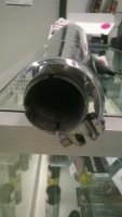
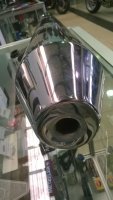
Finally, the transition to the header should occur with a sharp step. The header will have a significantly larger diameter than your exhaust port and the change to this larger diameter should be sudden, not smooth. This fast change helps to prevent reversion, especially at lower RPMs. Reversion is a killer of torque and so you can expect a bit more power down low and in the mid range with this step in place (especially if you're running a hotter cam). If, for some reason, this step doesn't exist in your system, an insert can usually correct the problem. I know MikesXS sells them, and they're not too hard to make, either. They look like this, and you can clearly see the sharp step created as you transition from the head to the header:
Header Design
When it comes to exhausts, there are two types of tuning with which you should be familiar. The first, called inertia tuning, which involves overall design of the exhaust and its length. The second, known as acoustic tuning (very similar concept as pulse tuning for intakes), is very important for two strokes, but also has an effect on four stroke engines. Both, however, are of some importance and so you should be familiar with the basics. As with my previous posts, I'll stick mainly to the four stroke applications.
Also, the majority of the design in an exhaust system will go into selections on the header. The gases in the exhaust system are the hottest just after they leave the cylinder and enter the header, so this is where many systems fall down. Correct sizing and lengths can make several percentage points of difference in peak numbers. Tweaking things here can also change the characteristics of the engine without having to open up the cases again, so if money isn't an object it's definitely worth exploring having several different header configurations.
Inertia Tuning
The concept behind inertia tuning is that the exhaust gases leave the cylinder in regular pulses and that these pulses tend to stick together as they travel through the exhaust system. This means that each pulse is a discrete unit of high pressure traveling through pipe and due to inertia, these pulses leave a low pressure zone behind them as they travel. The efficiency at which your cylinder is emptied of exhaust gases is directly related to the delta P between the cylinder and the header and so keeping the exhaust system in a low pressure state will translate into better volumetric efficiency and more torque.
The best design for inertia tuning has been shown to be a four-into-two-into-one (4:2:1) for best mid-range torque or four-into-one (4:1) for max power. Obviously, twins only get the 2:1 option.
Finally, we need to decide on a total length for the exhaust system (we'll handle lengths for the headers and collectors and such in the next section). For inertia tuning to work best, an exhaust pulse must be able to travel the entire length of the pipe before another pulse enters. It's OK to have two pulses in the pipe at once, but zero is bad. As a pulse leaves the end of the pipe, the low pressure zone in its wake will pull in gases from wherever possible. We want this low pressure zone acting on our cylinder to pull out more exhaust gases and not acting on the atmosphere to pull fresh air into the end of the muffler. Basically speaking, our exhaust needs to be long enough so that an exhaust pulse remains in the pipe up to the point at which another pulses is added. At 10,000 RPM, a new pulse is entering the pipe every 0.012 seconds. This means our pipe needs to be long enough for a pulse to travel its distance in .012 seconds (or more). If the pulse can travel the distance of the pipe in less than .012 seconds, we need a longer pipe.
Exhaust gases will usually travel at between 200 and 300 feet per second. Overly large exhaust pipe diameters will slow this speed (which isn't good) and pipe diameters that are too small will speed this up (also not good). I prefer to use the 300fps number as it's a bit of a worst case scenario. The actual speed of your exhaust gases can be calculated and I'll run through the math for that toward the end of this post. Just remember that if you set things up correctly, your exhaust gas velocity should fall somewhere in or very near this range.
So... now we know how fast our gases are traveling, the next thing we need to do is decide upon the ideal RPM at which we want our exhaust to work. Just like everything else, the total exhaust length should be tailored to the optimal RPM of your engine. For this example, I'll use 8,000 RPM. At 8,000 RPM, a four stroke engine is creating an exhaust pulse 4,000 times per minute. That reduces down to 66.7 times per second. One divided by 66.7 gives us an exhaust gas pulse every .015 seconds. We can then multiply our 300 feet per second value by .015 seconds to get our resulting length. We end up at 4.5 feet. If your desired RPM is higher, this length will reduce. If your desired RPM is lower, the pipes with be longer. When in doubt, err on the side of length. Chopping pipes too short seems to be a common design decision these days (looks?) and hurts power up until the point where the engine revs fast enough to take advantage. For pipes chopped up near the foot pegs, few bikes can even rev high enough to take advantage of this. Even if your bike can rev up to 15,000 (in theory), short pipes are hurting power until you get to those speeds and so your redline (in practice) may be lower. Looking at Honda's iconic RC166, we can see the pipes extend all the way to the back wheel, despite having a redline of 18,000 RPM.
Bear in mind that this calculation method applies to a single pipe per cylinder. For the more idealized approach of collected and merged header, total length will be shorter, again. For merged headers, the idea is to use the amount of time elapsed between each pulse of all the cylinders rather than each pulse from each cylinder. For bikes with more than two cylinders, use the Acoustic Tuning methods listed below. For 360° twins (XS650, Brit bikes, etc), take the total length and divide by two. 180° twins like the vintage Hondas should multiply the total length by a factor of .75.
Acoustic Tuning
Acoustical tuning in the exhaust system works on the same theory as pulse tuning in the intake system. When the exhaust gases explode from the cylinder and head through the exhaust system, a high pressure sound wave is generated. A low pressure wave reflects back from the high pressure wave as it exits the pipe and the idea is to time this low pressure wave to come back to the exhaust valve at the right time.
Strangely enough, the total length isn't so much as calculated as it is derived. By summing the lengths of the properly designed components, we end up at a more-or-less ideal total length. The length of the headers sort of changes the slopes of the peak torque curve. Longer headers will begin to generate more torque, sooner, but will cause a rapid drop off as RPMs increase. Short headers will do the opposite; a rapid increase in torque with a slower drop off.
In order to accurately size the header pipes, you will need to know your cam timing as well as the displacement of each cylinder. We'll get to the cam timing part in a minute, but we'll talk about displacement right now. The displacement of each cylinder dictates how much exhaust gases are generated. The amount of exhaust gas and the diameter of the header work together to dictate the speed of the exhaust gases.
Time for some math... First up, we need to know how much exhaust gas is being generated by your cylinder (not cylinders, we're only interested in one of them right now) at your ideal RPM. Falling back to my previous examples of my own CJ360, I'm aiming for an ideal engine speed of 8,000 RPM with a per cylinder displacement of 189cc.
The first thing to do is to decide on the inside diameter of the primary headers. The diameter of the header pipes is what determines the exhaust gas velocities. Smaller pipes increase the gas velocity and cause peak torque to occur earlier, while larger diameter pipes slow down gas velocities and cause peak torque to occur later. I'll touch on the heavier portions of the math later in this post, but for now, just take it on faith that each cylinder is generating 866cc of exhaust gases every period (two rotations per period). At 8,000 RPM, we're getting 4,000 pulses every minute and so this translates to 3,464,000cc of exhaust gas per minute. This is almost exactly 122.33 cubic feet of gas per minute.
Mr. A.G. Bell has been kind enough to test things thoroughly for us, and so we know that peak torque, from the exhaust system, generally occurs at 250 feet per second.
Using our ideal gas velocity and the amount of gas being generated at our desired RPM, it is now possible to calculate the inside diameter of the header pipe which will meet these requirements.
The formula for calculating gas velocity through a duct is v = q/A. v is the resulting velocity in feet per minute, q is the gas flow in cubic feet per minute, and A is the cross sectional area of the duct in question. We know the velocity is 250 feet per second and so we convert to feet per minute and get 15,000. Plug the values into the formula and we get 15000 = 101 / A. Algebra allows us to reconfigure the equation to solve for A. We now have A = 122.33 / 15000. A equals 0.008155 square feet. Convert back to inches and we have 1.17437. Because we're working with a circular pipe, it's time to break out the geometry skills. 1.17437 in² = pi*r². 1.17437 divided by pi give us .3738 = r². Take the square root of both sides and we now have r = .6114 inches. Double it to get our diameter and we're at 1.223 inches. The nearest sized standard pipe is 1.25 inches and so we'll make use of that.
Now that we have our pipe sized correctly, it's time to get the length of the header. The calculation for the length is fairly simple. Length, in inches, is equal to (((850 * (180 + EBBC)) / RPM) - 3. EBBC is the number of degrees before BDC that the exhaust valve opens. In my own engine, this number is 54° and so the calculation becomes (((850 * (180 + 54)) / RPM) - 3. Unlike other RPM selections, the RPM value used in this calculation should either be the redline of the engine, or the midpoint between peak torque and redline. I'll be using my redline of 11,000 RPM. Working the math through gives us an ideal primary header length of 15.1 inches. Should you ever arrive at a length of less than 15 inches, just go with 15. You don't want these things too short.
Before we talk about the next aspect of exhaust design, I'll give you a slightly easier method of pipe diameter selection. This method tends to result in a slightly larger diameter pipe, but it's a lot easier to follow (especially after I get to the "heavy" math section). After calculating the primary length, you can solve the issue of diameter by D = sqrt((cc / (pL + 3) * 25) * 2.1. Basically, take the square root of the cylinder displacement divided by the primary length plus 3, times 25. Then take that result and multiply by a further 2.1. Using the same numbers are my above calculations we end up with an inside diameter of 1.35 inches. When it comes time to match up to a standard pipe size of 1.375, this is only one step up from my original choice of 1.25 inches.
Secondary Headers
OK... with that out of the way, we can calculate the length of the secondary header. This part only applies if you're planning on running a 4:2:1 system (or basically any system that doesn't converge directly into one pipe, so this applies to 6:3:1 as well, but not 4:1 or 3:1 or even 6:1). The "secondary" nomenclature applies to the section that falls between the primary headers and the tail pipe. In four cylinder applications, this is the set of two, after the four, but before the one.
The length of the secondary header is calculated in very much the same way as the primary header, but with an important difference. The total length of the primary plus the secondary should be the value from the formula, multiplied by two. If the formula yields a value of less than 15 inches, the primary header should remain at fifteen inches and the secondary head should be shortened accordingly. For instance, if our formula gives us a length of 13 inches, we get 26 inches for the total length of both the primary and secondary headers. 15 of those inches are reserved for the primary header and the secondary header (and collector) should take up the remaining 11.
When adding a secondary header into the system, it is important to recalculate the diameter of the pipes being used. The secondary headers should be slightly larger in diameter. To calculate the value, raise the original value to the power of two and then multiply by two. Square that result and then multiply by .93. Round to the nearest standard pipe size and you're good to go. Going back to my original example of 1.223 inches we follow the math through like so: sqrt((1.223 * 1.223) * 2) * .93 = 1.609. Round to standard pipe sizes and the secondary headers should be 1.625.
Exhaust Tuning
One of the nice things about saving the exhaust system until last is that we can fine tune the engine to the desired levels without having to open it back up again. Changing primary and secondary header sizes and lengths will move and reshape the torque curve to match your desired characteristics.
For instance, if you want to lower the RPM at which peak torque occurs, you can reduce the diameter of the primary header (because secondary header diameter is derived from primary header diameter, don't forget to resize the secondary as well). A reduction in size of a single step will drop peak torque up to 1,000 RPMs lower. An increase in header length will result in lowering the peak torque as well. It's even possible to use unequal length headers to broaden the torque curve as one cylinder will hit peak torque before the other(s). On a four cylinder engine, you may decide to go -2 inches on one header, keep the second the same, and then go to +2 and +4 on the other two cylinders, respectively. This approach is clear to see on the CB400F pipes. They look good because they work well.
Collectors
One thing that hasn't yet been mentioned is collectors. The collector is the section of pipe that joins the primary headers to the secondary headers and the secondary headers to the tail pipe. The design of the collector can help to promote low-end torque. The most common type is what's known as the merge collector. The concept is that each of the header pipes smoothly transition into the collector rather then end abruptly. This type of collector is best suited toward maximum horsepower, but does little to promote any boost in torque in the lower RPM ranges. You'll also see these types of collectors in use for turbo manifolds. In this particular example, a venturi has been added in order to help scavenge gases. The venturi makes this design slightly more efficient from an inertial stand point.
Another type of collector is known as a baffle-type. In this design, each header ends abruptly and is joined by a single cone to the tail pipe (or secondary header). This design is simple to implement, but suffers for pure racing applications due to some turbulence as the exhaust gases merge. For street use, this is just fine.
Split interference collectors are kind of a halfway house between the two designs listed above. They're what you usually see in stock collectors. Each header will end abruptly, but instead of a simple cone for the collector, you get a smoother transition like you would see in a merge collector.
I'll talk a bit more about collector design in a future post, but for now, just be aware that there are different types and they don't all behave equally. It's not life-or-death differences though, either.
Tailpipe
Selecting the length of the tailpipe is fairly easy. Though I prefer to use the more complicated method I first listed a dozen paragraphs ago, you can always take the easy way out. If you've designed a system with secondary headers, simply double the length of the existing system and you'll be at the correct length. If only primary headers are being used, you'll want to quadruple the length. Going back to our original example of 15.1 inches for the primary headers, our total exhaust length ends up at 60.4 inches, or just over five feet. The length of the collector for the tailpipe should be included in this number.
The final diameter for the tailpipe is a fairly simple calculation as well. First, double the displacement of a single cylinder. Then divide that number by the primary length, plus three, and then multiplied by 25. Take the square root and then multiply by two. Now round to the nearest standard pipe size. For our example of 189cc per cylinder and primary length of 15.1 inches, the equation should look like this sqrt((189 * 2) / ((15.1 + 3) * 25) * 2. The result ends up at 1.83 inches which would round to 1.875 inches.
Mufflers
Unless you're making a full on race bike, you're going to want these. All things being equal (and I mean equal in the performance sense) then open pipes will generally produce the greatest level of horsepower. On the street, though, you're probably going to want some level of noise suppression. The drone of open pipes gets pretty old after the first few times. When selecting a muffler, you're going to want something that provides a decent level of noise control with the minimum amount of flow restriction. Unfortunately, these values are rarely listed by the manufacturer. If performance is more of a concern than money, try to stick to name brands with dyno-proven improvements over stock. Also, the length of the muffler should count toward the overall length of your exhaust system. Adjust things accordingly.
Tips and Tricks
There are a few little tricks you can pull to help things out even more. One of those is called "stepped headers". This is the same theory that is used to help two strokes out with exhaust design. The concept is that as the header lengthens, you widen the pipe once or twice along it's length. You only go up a step at a time and only need to do this once or, sometimes, twice. The first step is usually located between 10 and 14 inches from the head. Larger diameter header pipes will tend to favor the longer side of the 10-14 range while smaller diameters favor the shorter side. If a second step is desired, this one is usually located just an inch or two before the first collector.
Also, like the intake tract, the exhaust tract doesn't much care for lazy welds or rough spots. To keep the gases flowing, you want smooth surfaces with smooth transitions (steps, aside). Welds, as much as possible, should be ground down on the inside, especially around the flanges and the head where gas velocities are the highest.
Next, the header pipes should exit from the head in a relatively straight manner without too much of a bend.
Finally, if your design necessitates headers that are of a smaller ID than your exhaust ports, try to have the headers flared to match the exhaust port diameter. The ideal situation is one where the headers are of larger diameter than the ports, but if that ideal cannot be met, at least aim for the same diameter.
The Math
OK... I said I'd get to this part... This is how I calculated out the 866cc of exhaust gases per cylinder, per period. The reason I prefer this calculation over the simpler one is that it takes less for granted (or, at the very least, includes some extra variables which can be tweaked).
If you recall, the majority of the expansion of gases in a cylinder is due to the heat created by the combustion of the gasoline. We can take advantage of this fact by using the ideal gas law to figure out how much expansion the gases have undergone. All we need to know is the temperature of the mixture before the combustion event and the temperature of the gases after the combustion event. For these two values, I am going to assume 72°F and 1800°F. These numbers, of course, can be accurately measured with the correct equipment and I encourage that approach. When these temperatures are converted to the Rankine scale, the quotient between the two becomes the factor of expansion. For instance, 72°F is 531.67 Rankine and 1800°F is 2259.67 Rankine. 2259.67 / 531.67 = 4.25. So the gases will expand 4.25 times due to heat, alone.
Though that number alone is probably a decent facsimile, lets get a bit more accurate and also account for the expansion in volume due to the combustion of gasoline (liquid to a gas). For gasoline, we'll use C8H18 for its chemical representation and this gives us a molecular weight of 114. Stoichiometry tells us that 12.5 moles of Oxygen will be required to combust every 114 grams of gasoline and will result in an output of 8CO2 + 9H2O. Equal moles of gas are also equal in volume and so we know that the expansion in volume of the gasoline is going to come in at a factor of (8+9)/12.5 = 1.36. However, the presence of Oxygen in the atmosphere is around 21% and so only 21% of our intake gas is affected by this calculation. The final expansion in volume due to combustion can be calculated as (100 - 21) + (21*1.36) = 107.56%.
Going back to our rate of expansion due to temperatures, we can multiply that by 1.0756 to include the expansion due to combustion and multiply again by the displacement in our cylinder to get the final volume of the exhaust gases. 4.25 * 1.0756 * 189.58cc = 866.63cc.
Materials
One final thing before I finish this up. Use stainless steel wherever possible. A lot of the exhaust gas velocity is dependent upon the volume of the exhaust gases. As we know, as the gases cool, the volume decrease. This decreases pressure which decreases velocity. In order to help keep the exhaust gases hot, stainless steel is the material of choice when building exhaust systems. Other metals tend to be better conductors of heat and so stainless steel gets the nod in this application.
If, you find, during your sizing calculations that you regularly had to round up when choosing standard pipe size, the application of fiberglass header wrap can also net you a few extra ponies, especially toward the upper end of the RPM band. If you've routinely had to round down on sizes, you may be better off skipping the header wrap (unless you're trying to shield something from the heat).
Conclusion
Despite the length of this post, I'm hoping that the details behind a decent exhaust system seem a bit easier to comprehend. Like everything else, it's not black magic. Selecting the correct lengths and sizes of your tubing is 90% of the battle. Quality welds and smooth bends are the rest.
If you have access to a dyno, experiment with different lengths and sizes. Pretty much everything listed above is just rule of thumb kind of stuff. It'll get you into the ball park, but the home runs are only hit after empirical data is collected.
Sent from my iPad using Tapatalk
Applications - Exhaust Design
Time for a new post, I figure. As you may have expected, one of the major areas still to cover is the exhaust system. I've
saved this item until now because your design at this point is going to be very dependent upon earlier selections. Furthermore,
there are several options you can take in order to change the overall characteristics of your engine (for good or bad) with only
a little regard as to your previous choices. In short, the exhaust system is one of those areas where you can really make a
difference in the performance of your bike, especially in bikes as old as ours. Even in newer machines, it is not uncommon to
see exhaust changes as the primary means of modification in engine performance. For those of you guys riding smokers, the
exhaust design is, arguably, the single most performance consideration.
As with previous posts, the plan is to break this up into manageable chunks. Each subsection will deal with a different
consideration and will hopefully tie it all together as we reach the end of this post.
Before we begin, there are a few things you'll need to know in order to make the best use of this information. First, you need
to know your displacement as well as the number of cylinders on your bike. If you don't know these first two things, please hand your keys over and go buy a Toyota. Second, you need to know the exhaust timing on your selected cam. Finally, like with most everything else, you need to have a general idea as to where you'd like your peak torque to occur.
Exhaust Valves and Ports
The first part of the exhaust system actually begins inside the head. Like intake valves and ports, a three or five angle grind will provide benefit here. But unlike intake valves, less emphasis is placed on things like tapered stems or backcutting. The reason being is that the gases exiting the engine are under much higher pressure than the mixture when it enters. This created a much greater pressure differential between the cylinder and exhaust system than that is between the cylinder and the intake system. This greater differential (often called "delta P") means that the little details become less important and the bigger picture become more important. In this case, the bigger details are exhaust valve and port sizes. The traditional approach is that exhaust valves should be sized at approximately 80% the size of the intake valves. Hemispherical heads with a sharper include angle will benefit from slightly larger exhaust valves due to the tight radius the exhaust ports must follow. This design philosophy is clearly visible in the ratios seen in the Honda 350s and 360s (34mm intake valve, 28mm exhaust valve, 82.4% sizing ratio).
For exhaust ports, the diameter should be the same as the valve size (or only slightly smaller). Usually they are smaller and so taking some metal out could be a good idea. Pay special attention to the port ceiling as this is where most of the gains will occur. Also, like intake ports, a 'D' shape with a flat floor will generally out perform purely circular ports. Exhaust port walls should be as smooth as possible and can be sanded down as fine as 800 grit paper.
Finally, the transition to the header should occur with a sharp step. The header will have a significantly larger diameter than your exhaust port and the change to this larger diameter should be sudden, not smooth. This fast change helps to prevent reversion, especially at lower RPMs. Reversion is a killer of torque and so you can expect a bit more power down low and in the mid range with this step in place (especially if you're running a hotter cam). If, for some reason, this step doesn't exist in your system, an insert can usually correct the problem. I know MikesXS sells them, and they're not too hard to make, either. They look like this, and you can clearly see the sharp step created as you transition from the head to the header:
Header Design
When it comes to exhausts, there are two types of tuning with which you should be familiar. The first, called inertia tuning, which involves overall design of the exhaust and its length. The second, known as acoustic tuning (very similar concept as pulse tuning for intakes), is very important for two strokes, but also has an effect on four stroke engines. Both, however, are of some importance and so you should be familiar with the basics. As with my previous posts, I'll stick mainly to the four stroke applications.
Also, the majority of the design in an exhaust system will go into selections on the header. The gases in the exhaust system are the hottest just after they leave the cylinder and enter the header, so this is where many systems fall down. Correct sizing and lengths can make several percentage points of difference in peak numbers. Tweaking things here can also change the characteristics of the engine without having to open up the cases again, so if money isn't an object it's definitely worth exploring having several different header configurations.
Inertia Tuning
The concept behind inertia tuning is that the exhaust gases leave the cylinder in regular pulses and that these pulses tend to stick together as they travel through the exhaust system. This means that each pulse is a discrete unit of high pressure traveling through pipe and due to inertia, these pulses leave a low pressure zone behind them as they travel. The efficiency at which your cylinder is emptied of exhaust gases is directly related to the delta P between the cylinder and the header and so keeping the exhaust system in a low pressure state will translate into better volumetric efficiency and more torque.
The best design for inertia tuning has been shown to be a four-into-two-into-one (4:2:1) for best mid-range torque or four-into-one (4:1) for max power. Obviously, twins only get the 2:1 option.
Finally, we need to decide on a total length for the exhaust system (we'll handle lengths for the headers and collectors and such in the next section). For inertia tuning to work best, an exhaust pulse must be able to travel the entire length of the pipe before another pulse enters. It's OK to have two pulses in the pipe at once, but zero is bad. As a pulse leaves the end of the pipe, the low pressure zone in its wake will pull in gases from wherever possible. We want this low pressure zone acting on our cylinder to pull out more exhaust gases and not acting on the atmosphere to pull fresh air into the end of the muffler. Basically speaking, our exhaust needs to be long enough so that an exhaust pulse remains in the pipe up to the point at which another pulses is added. At 10,000 RPM, a new pulse is entering the pipe every 0.012 seconds. This means our pipe needs to be long enough for a pulse to travel its distance in .012 seconds (or more). If the pulse can travel the distance of the pipe in less than .012 seconds, we need a longer pipe.
Exhaust gases will usually travel at between 200 and 300 feet per second. Overly large exhaust pipe diameters will slow this speed (which isn't good) and pipe diameters that are too small will speed this up (also not good). I prefer to use the 300fps number as it's a bit of a worst case scenario. The actual speed of your exhaust gases can be calculated and I'll run through the math for that toward the end of this post. Just remember that if you set things up correctly, your exhaust gas velocity should fall somewhere in or very near this range.
So... now we know how fast our gases are traveling, the next thing we need to do is decide upon the ideal RPM at which we want our exhaust to work. Just like everything else, the total exhaust length should be tailored to the optimal RPM of your engine. For this example, I'll use 8,000 RPM. At 8,000 RPM, a four stroke engine is creating an exhaust pulse 4,000 times per minute. That reduces down to 66.7 times per second. One divided by 66.7 gives us an exhaust gas pulse every .015 seconds. We can then multiply our 300 feet per second value by .015 seconds to get our resulting length. We end up at 4.5 feet. If your desired RPM is higher, this length will reduce. If your desired RPM is lower, the pipes with be longer. When in doubt, err on the side of length. Chopping pipes too short seems to be a common design decision these days (looks?) and hurts power up until the point where the engine revs fast enough to take advantage. For pipes chopped up near the foot pegs, few bikes can even rev high enough to take advantage of this. Even if your bike can rev up to 15,000 (in theory), short pipes are hurting power until you get to those speeds and so your redline (in practice) may be lower. Looking at Honda's iconic RC166, we can see the pipes extend all the way to the back wheel, despite having a redline of 18,000 RPM.
Bear in mind that this calculation method applies to a single pipe per cylinder. For the more idealized approach of collected and merged header, total length will be shorter, again. For merged headers, the idea is to use the amount of time elapsed between each pulse of all the cylinders rather than each pulse from each cylinder. For bikes with more than two cylinders, use the Acoustic Tuning methods listed below. For 360° twins (XS650, Brit bikes, etc), take the total length and divide by two. 180° twins like the vintage Hondas should multiply the total length by a factor of .75.
Acoustic Tuning
Acoustical tuning in the exhaust system works on the same theory as pulse tuning in the intake system. When the exhaust gases explode from the cylinder and head through the exhaust system, a high pressure sound wave is generated. A low pressure wave reflects back from the high pressure wave as it exits the pipe and the idea is to time this low pressure wave to come back to the exhaust valve at the right time.
Strangely enough, the total length isn't so much as calculated as it is derived. By summing the lengths of the properly designed components, we end up at a more-or-less ideal total length. The length of the headers sort of changes the slopes of the peak torque curve. Longer headers will begin to generate more torque, sooner, but will cause a rapid drop off as RPMs increase. Short headers will do the opposite; a rapid increase in torque with a slower drop off.
In order to accurately size the header pipes, you will need to know your cam timing as well as the displacement of each cylinder. We'll get to the cam timing part in a minute, but we'll talk about displacement right now. The displacement of each cylinder dictates how much exhaust gases are generated. The amount of exhaust gas and the diameter of the header work together to dictate the speed of the exhaust gases.
Time for some math... First up, we need to know how much exhaust gas is being generated by your cylinder (not cylinders, we're only interested in one of them right now) at your ideal RPM. Falling back to my previous examples of my own CJ360, I'm aiming for an ideal engine speed of 8,000 RPM with a per cylinder displacement of 189cc.
The first thing to do is to decide on the inside diameter of the primary headers. The diameter of the header pipes is what determines the exhaust gas velocities. Smaller pipes increase the gas velocity and cause peak torque to occur earlier, while larger diameter pipes slow down gas velocities and cause peak torque to occur later. I'll touch on the heavier portions of the math later in this post, but for now, just take it on faith that each cylinder is generating 866cc of exhaust gases every period (two rotations per period). At 8,000 RPM, we're getting 4,000 pulses every minute and so this translates to 3,464,000cc of exhaust gas per minute. This is almost exactly 122.33 cubic feet of gas per minute.
Mr. A.G. Bell has been kind enough to test things thoroughly for us, and so we know that peak torque, from the exhaust system, generally occurs at 250 feet per second.
Using our ideal gas velocity and the amount of gas being generated at our desired RPM, it is now possible to calculate the inside diameter of the header pipe which will meet these requirements.
The formula for calculating gas velocity through a duct is v = q/A. v is the resulting velocity in feet per minute, q is the gas flow in cubic feet per minute, and A is the cross sectional area of the duct in question. We know the velocity is 250 feet per second and so we convert to feet per minute and get 15,000. Plug the values into the formula and we get 15000 = 101 / A. Algebra allows us to reconfigure the equation to solve for A. We now have A = 122.33 / 15000. A equals 0.008155 square feet. Convert back to inches and we have 1.17437. Because we're working with a circular pipe, it's time to break out the geometry skills. 1.17437 in² = pi*r². 1.17437 divided by pi give us .3738 = r². Take the square root of both sides and we now have r = .6114 inches. Double it to get our diameter and we're at 1.223 inches. The nearest sized standard pipe is 1.25 inches and so we'll make use of that.
Now that we have our pipe sized correctly, it's time to get the length of the header. The calculation for the length is fairly simple. Length, in inches, is equal to (((850 * (180 + EBBC)) / RPM) - 3. EBBC is the number of degrees before BDC that the exhaust valve opens. In my own engine, this number is 54° and so the calculation becomes (((850 * (180 + 54)) / RPM) - 3. Unlike other RPM selections, the RPM value used in this calculation should either be the redline of the engine, or the midpoint between peak torque and redline. I'll be using my redline of 11,000 RPM. Working the math through gives us an ideal primary header length of 15.1 inches. Should you ever arrive at a length of less than 15 inches, just go with 15. You don't want these things too short.
Before we talk about the next aspect of exhaust design, I'll give you a slightly easier method of pipe diameter selection. This method tends to result in a slightly larger diameter pipe, but it's a lot easier to follow (especially after I get to the "heavy" math section). After calculating the primary length, you can solve the issue of diameter by D = sqrt((cc / (pL + 3) * 25) * 2.1. Basically, take the square root of the cylinder displacement divided by the primary length plus 3, times 25. Then take that result and multiply by a further 2.1. Using the same numbers are my above calculations we end up with an inside diameter of 1.35 inches. When it comes time to match up to a standard pipe size of 1.375, this is only one step up from my original choice of 1.25 inches.
Secondary Headers
OK... with that out of the way, we can calculate the length of the secondary header. This part only applies if you're planning on running a 4:2:1 system (or basically any system that doesn't converge directly into one pipe, so this applies to 6:3:1 as well, but not 4:1 or 3:1 or even 6:1). The "secondary" nomenclature applies to the section that falls between the primary headers and the tail pipe. In four cylinder applications, this is the set of two, after the four, but before the one.
The length of the secondary header is calculated in very much the same way as the primary header, but with an important difference. The total length of the primary plus the secondary should be the value from the formula, multiplied by two. If the formula yields a value of less than 15 inches, the primary header should remain at fifteen inches and the secondary head should be shortened accordingly. For instance, if our formula gives us a length of 13 inches, we get 26 inches for the total length of both the primary and secondary headers. 15 of those inches are reserved for the primary header and the secondary header (and collector) should take up the remaining 11.
When adding a secondary header into the system, it is important to recalculate the diameter of the pipes being used. The secondary headers should be slightly larger in diameter. To calculate the value, raise the original value to the power of two and then multiply by two. Square that result and then multiply by .93. Round to the nearest standard pipe size and you're good to go. Going back to my original example of 1.223 inches we follow the math through like so: sqrt((1.223 * 1.223) * 2) * .93 = 1.609. Round to standard pipe sizes and the secondary headers should be 1.625.
Exhaust Tuning
One of the nice things about saving the exhaust system until last is that we can fine tune the engine to the desired levels without having to open it back up again. Changing primary and secondary header sizes and lengths will move and reshape the torque curve to match your desired characteristics.
For instance, if you want to lower the RPM at which peak torque occurs, you can reduce the diameter of the primary header (because secondary header diameter is derived from primary header diameter, don't forget to resize the secondary as well). A reduction in size of a single step will drop peak torque up to 1,000 RPMs lower. An increase in header length will result in lowering the peak torque as well. It's even possible to use unequal length headers to broaden the torque curve as one cylinder will hit peak torque before the other(s). On a four cylinder engine, you may decide to go -2 inches on one header, keep the second the same, and then go to +2 and +4 on the other two cylinders, respectively. This approach is clear to see on the CB400F pipes. They look good because they work well.
Collectors
One thing that hasn't yet been mentioned is collectors. The collector is the section of pipe that joins the primary headers to the secondary headers and the secondary headers to the tail pipe. The design of the collector can help to promote low-end torque. The most common type is what's known as the merge collector. The concept is that each of the header pipes smoothly transition into the collector rather then end abruptly. This type of collector is best suited toward maximum horsepower, but does little to promote any boost in torque in the lower RPM ranges. You'll also see these types of collectors in use for turbo manifolds. In this particular example, a venturi has been added in order to help scavenge gases. The venturi makes this design slightly more efficient from an inertial stand point.
Another type of collector is known as a baffle-type. In this design, each header ends abruptly and is joined by a single cone to the tail pipe (or secondary header). This design is simple to implement, but suffers for pure racing applications due to some turbulence as the exhaust gases merge. For street use, this is just fine.
Split interference collectors are kind of a halfway house between the two designs listed above. They're what you usually see in stock collectors. Each header will end abruptly, but instead of a simple cone for the collector, you get a smoother transition like you would see in a merge collector.
I'll talk a bit more about collector design in a future post, but for now, just be aware that there are different types and they don't all behave equally. It's not life-or-death differences though, either.
Tailpipe
Selecting the length of the tailpipe is fairly easy. Though I prefer to use the more complicated method I first listed a dozen paragraphs ago, you can always take the easy way out. If you've designed a system with secondary headers, simply double the length of the existing system and you'll be at the correct length. If only primary headers are being used, you'll want to quadruple the length. Going back to our original example of 15.1 inches for the primary headers, our total exhaust length ends up at 60.4 inches, or just over five feet. The length of the collector for the tailpipe should be included in this number.
The final diameter for the tailpipe is a fairly simple calculation as well. First, double the displacement of a single cylinder. Then divide that number by the primary length, plus three, and then multiplied by 25. Take the square root and then multiply by two. Now round to the nearest standard pipe size. For our example of 189cc per cylinder and primary length of 15.1 inches, the equation should look like this sqrt((189 * 2) / ((15.1 + 3) * 25) * 2. The result ends up at 1.83 inches which would round to 1.875 inches.
Mufflers
Unless you're making a full on race bike, you're going to want these. All things being equal (and I mean equal in the performance sense) then open pipes will generally produce the greatest level of horsepower. On the street, though, you're probably going to want some level of noise suppression. The drone of open pipes gets pretty old after the first few times. When selecting a muffler, you're going to want something that provides a decent level of noise control with the minimum amount of flow restriction. Unfortunately, these values are rarely listed by the manufacturer. If performance is more of a concern than money, try to stick to name brands with dyno-proven improvements over stock. Also, the length of the muffler should count toward the overall length of your exhaust system. Adjust things accordingly.
Tips and Tricks
There are a few little tricks you can pull to help things out even more. One of those is called "stepped headers". This is the same theory that is used to help two strokes out with exhaust design. The concept is that as the header lengthens, you widen the pipe once or twice along it's length. You only go up a step at a time and only need to do this once or, sometimes, twice. The first step is usually located between 10 and 14 inches from the head. Larger diameter header pipes will tend to favor the longer side of the 10-14 range while smaller diameters favor the shorter side. If a second step is desired, this one is usually located just an inch or two before the first collector.
Also, like the intake tract, the exhaust tract doesn't much care for lazy welds or rough spots. To keep the gases flowing, you want smooth surfaces with smooth transitions (steps, aside). Welds, as much as possible, should be ground down on the inside, especially around the flanges and the head where gas velocities are the highest.
Next, the header pipes should exit from the head in a relatively straight manner without too much of a bend.
Finally, if your design necessitates headers that are of a smaller ID than your exhaust ports, try to have the headers flared to match the exhaust port diameter. The ideal situation is one where the headers are of larger diameter than the ports, but if that ideal cannot be met, at least aim for the same diameter.
The Math
OK... I said I'd get to this part... This is how I calculated out the 866cc of exhaust gases per cylinder, per period. The reason I prefer this calculation over the simpler one is that it takes less for granted (or, at the very least, includes some extra variables which can be tweaked).
If you recall, the majority of the expansion of gases in a cylinder is due to the heat created by the combustion of the gasoline. We can take advantage of this fact by using the ideal gas law to figure out how much expansion the gases have undergone. All we need to know is the temperature of the mixture before the combustion event and the temperature of the gases after the combustion event. For these two values, I am going to assume 72°F and 1800°F. These numbers, of course, can be accurately measured with the correct equipment and I encourage that approach. When these temperatures are converted to the Rankine scale, the quotient between the two becomes the factor of expansion. For instance, 72°F is 531.67 Rankine and 1800°F is 2259.67 Rankine. 2259.67 / 531.67 = 4.25. So the gases will expand 4.25 times due to heat, alone.
Though that number alone is probably a decent facsimile, lets get a bit more accurate and also account for the expansion in volume due to the combustion of gasoline (liquid to a gas). For gasoline, we'll use C8H18 for its chemical representation and this gives us a molecular weight of 114. Stoichiometry tells us that 12.5 moles of Oxygen will be required to combust every 114 grams of gasoline and will result in an output of 8CO2 + 9H2O. Equal moles of gas are also equal in volume and so we know that the expansion in volume of the gasoline is going to come in at a factor of (8+9)/12.5 = 1.36. However, the presence of Oxygen in the atmosphere is around 21% and so only 21% of our intake gas is affected by this calculation. The final expansion in volume due to combustion can be calculated as (100 - 21) + (21*1.36) = 107.56%.
Going back to our rate of expansion due to temperatures, we can multiply that by 1.0756 to include the expansion due to combustion and multiply again by the displacement in our cylinder to get the final volume of the exhaust gases. 4.25 * 1.0756 * 189.58cc = 866.63cc.
Materials
One final thing before I finish this up. Use stainless steel wherever possible. A lot of the exhaust gas velocity is dependent upon the volume of the exhaust gases. As we know, as the gases cool, the volume decrease. This decreases pressure which decreases velocity. In order to help keep the exhaust gases hot, stainless steel is the material of choice when building exhaust systems. Other metals tend to be better conductors of heat and so stainless steel gets the nod in this application.
If, you find, during your sizing calculations that you regularly had to round up when choosing standard pipe size, the application of fiberglass header wrap can also net you a few extra ponies, especially toward the upper end of the RPM band. If you've routinely had to round down on sizes, you may be better off skipping the header wrap (unless you're trying to shield something from the heat).
Conclusion
Despite the length of this post, I'm hoping that the details behind a decent exhaust system seem a bit easier to comprehend. Like everything else, it's not black magic. Selecting the correct lengths and sizes of your tubing is 90% of the battle. Quality welds and smooth bends are the rest.
If you have access to a dyno, experiment with different lengths and sizes. Pretty much everything listed above is just rule of thumb kind of stuff. It'll get you into the ball park, but the home runs are only hit after empirical data is collected.
Sent from my iPad using Tapatalk