Ok, since you obviously have been putting some thought into all of this, I'll take a shot at explanation without a diagram.
First, there is nothing pertinent in comparing the action of a telescopic fork and the linkage of your rear suspension, even with the simple rear system system here. The reason is that the telescopic front suspension has straight linear action that has no change due to mechanical articulation like the linkage at the rear. The rear shock itself is in fact identical to the fork leg, but unlike the front, the rear has the linkage that adds additional complexity. For the sake of simplification, let's ignore the importance of the angle between the road surface to the angle of motion of the wheels, or even that of any of the suspension components. I'm not saying there is nothing to talk about here, just that it clouds the topic at hand and is another layer of designing the system overall. Here we are only looking at the rate of change in the rear suspension due to the effect of the linkage only. So lets look at just the bare bones of such a system.
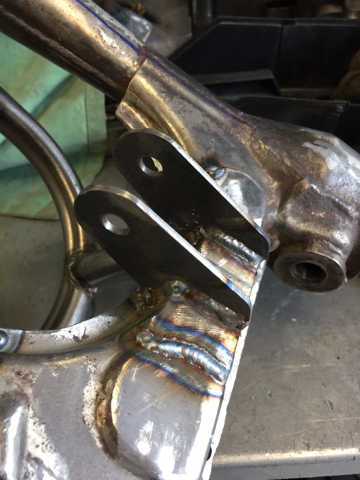
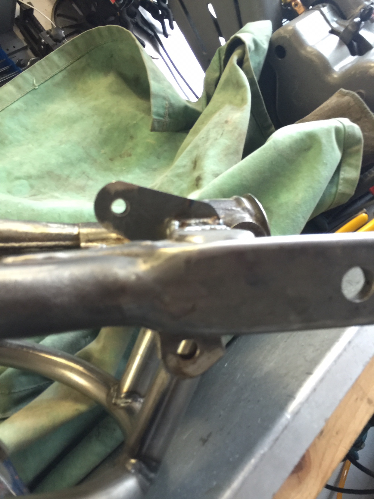
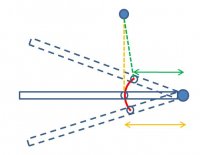
Consider a simpler model that contains the same bits as the one on your bike. Paring it down to just the required components, we have a single link that pivots at one end on a fixed base. Think main bearing on a crankshaft. The other end is attached to our shock/spring assembly. The other end of which is again attached to a fixed base. Exactly like your bike, just imagine that you have cut off the swingarm just ahead of the shock mount and mounted the frame in a vise. Now imagine the shock is much longer and has lots more travel - enough so that you can rotate what's left of the swing arm 180o, from straight down to straight up, and that the upper shock mount is directly above the swingarm fixed pivot. Just like a crank, connecting rod and piston, except the piston is fixed and the con rod is replaced with the telescoping shock. Let us imagine rotating this model clockwise, imitating the rotation of your swingarm when viewed from the right side of your bike. This may seem like an extreme and unrealistic scenario, but looking at the extreme condition often makes it simpler to visualize the way things change through the motion.
Starting at the due south position, you can easily see that rotating the crank, say 10 degrees compresses the shock hardly at all. You get a lot of rotation with very little travel of the shock. If you were using your hand instead of the shock to resist the motion of the crank, you would find it very difficult. Conversely, rotating the crank against the shock would be easy at this point - in fact infinitely easy at due south, where there is no compression of the shock at all. Crank it 1o, and you could easily begin to compress even a very strong spring. but 2o will be harder, 3o even harder and as the crank rotates to 30 or 40 degrees will become very hard indeed. However, at 40o, you are compressing the shock significantly more distance than at 30o, and massively more than at 3o. This increase per degree of rotation will continue on until somewhat past 90o and then fall back off at a similar declining rate of compression vs. rotation until 180o, where tiny rotation of the crank essentially makes for zero compression of the shock. The reason that the max distance traveled by the shock is past 90o crank rotation is because the actual maximum shock travel per crank degree is where 90o between the crank arm and shock occurs, and actually has nothing directly to do with crank degrees. With this in mind, look again at 0 crank degrees; the crank/shock degree relationship is zero. At a few degree, the crank/shock angle is very acute. As the crank rotates further, this angle becomes less and less acute until it becomes 90o. This is the point where the shock/spring has the most mechanical advantage over the crank. If you were to re-attach your swingarm, this is the point where the system will place the highest spring rate and damping due to the linkage. So you can see, if you were somehow to use this exaggerated rotation/travel, at the beginning, at 0 crankshaft degrees, your effective spring rate would be zero, and there would be no damping at all regardless of shock and spring, but both would rapidly increase to max as the shock/crank angle increases to 90o. This is typically the concept one starts with in thinking over something like a suspension, as you likely want very low spring/damping resistance for tiny impacts like a cigarette butt, but need much more when hitting a pothole.
But consider what happens after the 90+ degrees of crank rotation when the crank/shock angle gets to 90o. The angle continues to get bigger, but the shock compression per degree of rotation begins to fall. Where it will be very hard indeed to keep compressing the shock at 90o, at 130o it will be much easier, and at 180o it will be so easy that the only resistance to rotation will be from the bearings, and the shock will have again zero damping and the spring will have zero rotational effort. In your current configuration, you are somewhere in this second half of this hypothetical model, where the farther you rotate the arm, the less per rotational degree you compress the shock.
This may seem to be a fairly dire situation, but there is a bit more to consider. The spring does not offer a constant resisting force to the compression of the system. It accumulates in proportion to the compression distance. So even though the mechanical advantage due to the linkage of the shock/spring over the swingarm is getting lower the farther it rotates, the spring pressure is still increasing because it is only dependent on the distance it is compressed; the farther it is compressed, the more pressure it exerts. The shock, on the other hand, is not. It's function is dependent on the rate at which it is compressed. It does not care how far it is compressed, only how fast it is compressed regardless of where it happens to be travel wise. This means that even if you have a digressive linkage, depending on how digressive and what the spring rate is, you can still end up with enough spring pressure. The damping however will be reduced the farther the travel regardless. The other aspect is that the actual degrees of rotation in the swing arm are fairly small compared to the 90o of our model, so as long as you are a lot closer to the 90o end than the 180o end you will see fairly small digressive rate change.
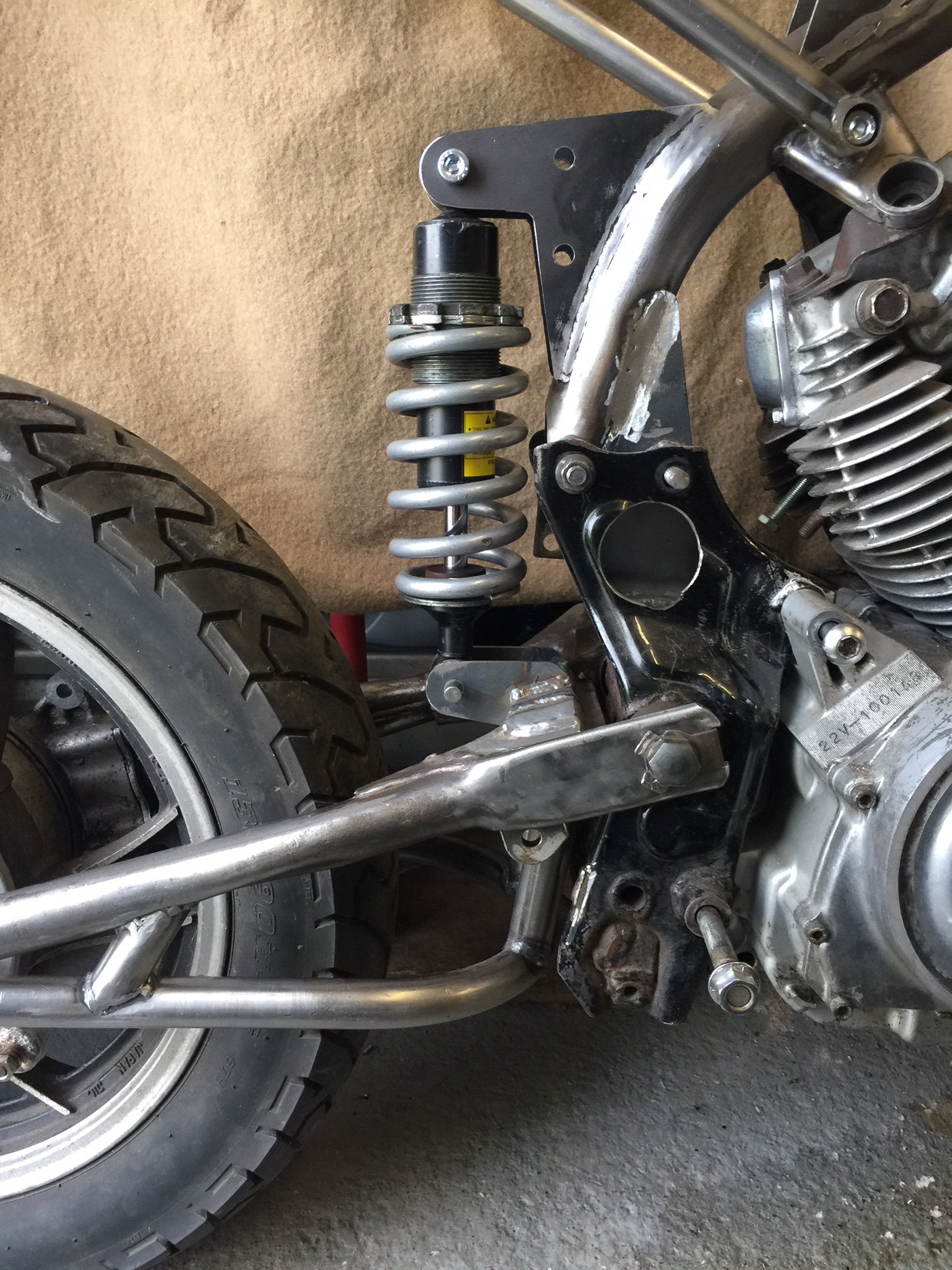
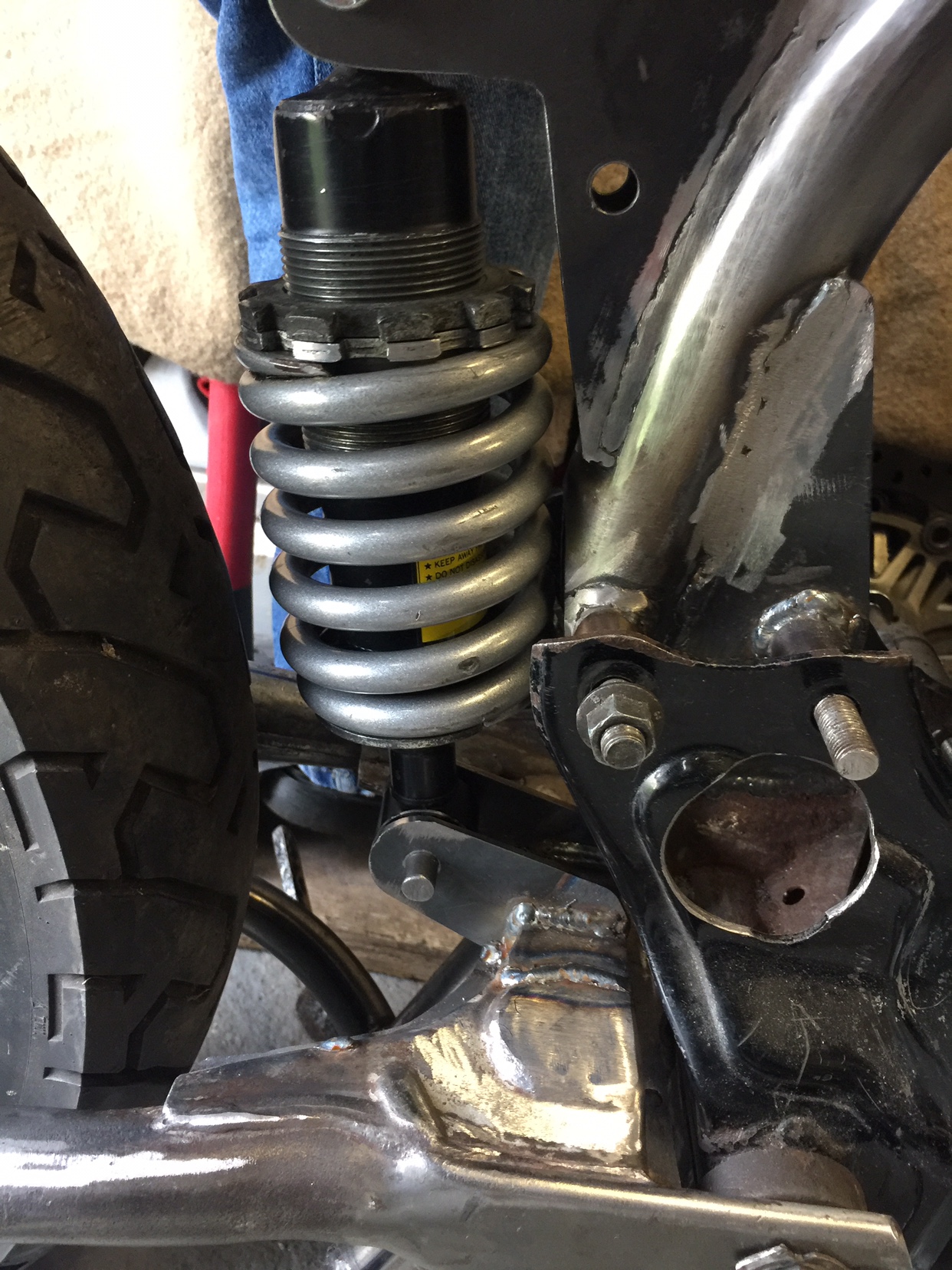
Returning to the first 90o+ of crank rotation, where we are in the progressive portion, with the simple scheme where the swingarm itself is the crank, in addition to designing an appropriate crank/shock angle, there are some other important considerations. As previously noted, the swing arm actually rotates only a small amount. With the shock directly attached to the arm close to the arm's pivot, the distance traveled there is consequently very small even at the intended 90o at max leverage. This requires a very strong spring and robust damping to resist the very long leverage, as the distance the spring/shock will compress is very small. This is where all of the many linkage systems come into play. If you add connecting rods (dog bones) and bell-cranks/rockers to the system, you can add a lot more travel, which will require a less strong/robust shock/spring. Additionally, you can create a lot more rotation in the rocker compared to the swingarm, and glean the benefits of a very steep progression akin to our 180o model (if desired). It all gets a bit tricky, as such systems commonly have digressive rates at some links and progressive rates at others, and it's the net effect that counts. What is likely to be important to you is your shock/spring selection. Many shocks are designed around these more complex setups and so need weaker springs and have longer travel than your system might require. So you should try to use a shock that had a non-linkage setup like yours as its original implementation. An easy way to see if you are in the ballpark is to measure the full travel of the shock with the spring removed. It need to be quite close to the travel you expect to see in your own set up.

")