OK folks...
We finally have a working prototype design for our fuse box and we're going to production!
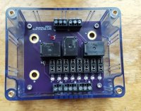
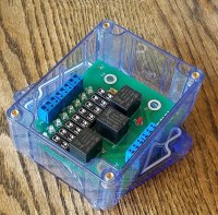
At this point in the process, we have not yet finalized a manufacturer and we're still investigating a couple of different options, but the design work is complete and tested on a few different bikes. What you see in the attached picture is the main portion of what you'll be receiving (color of the board may vary), but will also include a full set of fuses (all will be 10A) and the lid of the enclosure will have a sticker with each circuit listed so that you can label it for your own use. Printed installation instructions will also be included. The enclosure will be unmodified, so you will need a drill (drill press recommended) to complete the installation.
We're offering this pre-sale option to help handle initial production codes, which are expected to be several thousand dollars.
Pre-sale price on these boards is $100 for one board or $90 each for more than one. Depending on the manufacturer we go with, final retail price will be between the $125 and $150 mark, meaning you might save as much as 40% by ordering early. We will also be offering a separate off-board subharness that will include a 30A relay and main fuse. These subharness will be offered to early adopters at $25 each and will later be available for purchase at $40 each.
We're probably going to run this pre-sale for a couple of months, but the actual time is yet undermined. Once we have finalized the manufacturer and decided on initial run quantities, I'll let everyone know about the closing date.
If you're up for it, please let me know and I will send you a PayPal invoice.
I'm happy to answer any additional questions here, or by email at info@sparckmoto.com.
Thanks again for all the help with this,
Matt
We finally have a working prototype design for our fuse box and we're going to production!
At this point in the process, we have not yet finalized a manufacturer and we're still investigating a couple of different options, but the design work is complete and tested on a few different bikes. What you see in the attached picture is the main portion of what you'll be receiving (color of the board may vary), but will also include a full set of fuses (all will be 10A) and the lid of the enclosure will have a sticker with each circuit listed so that you can label it for your own use. Printed installation instructions will also be included. The enclosure will be unmodified, so you will need a drill (drill press recommended) to complete the installation.
We're offering this pre-sale option to help handle initial production codes, which are expected to be several thousand dollars.
Pre-sale price on these boards is $100 for one board or $90 each for more than one. Depending on the manufacturer we go with, final retail price will be between the $125 and $150 mark, meaning you might save as much as 40% by ordering early. We will also be offering a separate off-board subharness that will include a 30A relay and main fuse. These subharness will be offered to early adopters at $25 each and will later be available for purchase at $40 each.
We're probably going to run this pre-sale for a couple of months, but the actual time is yet undermined. Once we have finalized the manufacturer and decided on initial run quantities, I'll let everyone know about the closing date.
If you're up for it, please let me know and I will send you a PayPal invoice.
I'm happy to answer any additional questions here, or by email at info@sparckmoto.com.
Thanks again for all the help with this,
Matt