MV Agusta RS150 1968

davidc

Been Around the Block
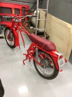
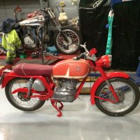
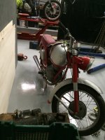
I recently picked up an MV Agusta RS150 a 1968 model in Italy.
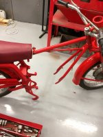
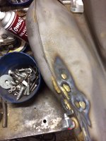
It's badly corroded but is running and will come up nicely.
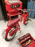
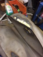
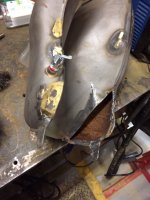
I've stripped it and sent the parts for acid strip and blasting using iron particles - first photos attached and I'll send on a few more as I put it back together.

Anyone with any idea on how the electrical system works - I have a manual in Italian and a sort of wiring diagram- but it looks very suspicious and the components are corroded, hardened and there are a few oddities within the head lamp unit and a diode set of sorts at the horn

Bye for now

David C
[/img][/img][/img][/img]
 

Attachments

  • RHS Full bike.jpg
    RHS Full bike.jpg
    275.6 KB · Views: 362
Wow, lovely little bike. Could you please elaborate what you mean by "picked up in Italy"? Are you in Europe already or did you import this into the US?
 
Sorry meant to say- I'm in Ireland but had it freighted to here via the previous owner, who removed the fuel, oil and battery and crated it for me.
total price to date $2500.00
 
Interesting little scoot. That seat is... Different. ;)

Sorry, no help here on the electrical bits but definitely following along.
 
Mabe ask around over here: http://www.mvagusta.net/forum/showthread.php?p=1854482#/forumsite/20748
 
Hi all!
My first post here:
You can download a handbook in English here:
http://www.mv-agusta-club-schweiz.ch/img/PDF/Handbuecher/klassisch/17_MV150RS_MV150GT_RS.pdf
and a parts list:
http://www.mv-agusta-club-schweiz.ch/img/PDF/Handbuecher/klassisch/17_MV150RS_catalogo_parti_ricambio.pdf
Some months ago my italian friend had a MV 150 RS but there were no diodes at the horn.
Wiring loom with diagram here:
http://www.ebay.at/itm/IMPIANTO-ELETTRICO-ELECTRICAL-WIRING-MOTO-MV-AGUSTA-150-RS-CON-SCHEMA-ELETTRICO-/141913932517?hash=item210abac2e5:g:p08AAOSw1S9WdYL4

Greetings from Ravensburg, Germany
Uli
 
Thanks- I got that hand book and manual from there already and I am on the MV forum.

I will see how I get on during the rebuild with regards to the ignition, charging etc

Regards

David C
 
rivera said:
Hi all!
My first post here:
You can download a handbook in English here:
http://www.mv-agusta-club-schweiz.ch/img/PDF/Handbuecher/klassisch/17_MV150RS_MV150GT_RS.pdf
and a parts list:
http://www.mv-agusta-club-schweiz.ch/img/PDF/Handbuecher/klassisch/17_MV150RS_catalogo_parti_ricambio.pdf
Some months ago my italian friend had a MV 150 RS but there were no diodes at the horn.
Wiring loom with diagram here:
http://www.ebay.at/itm/IMPIANTO-ELETTRICO-ELECTRICAL-WIRING-MOTO-MV-AGUSTA-150-RS-CON-SCHEMA-ELETTRICO-/141913932517?hash=item210abac2e5:g:p08AAOSw1S9WdYL4

Greetings from Ravensburg, Germany
Uli

Rivera- thanks for info - I hope I didn't come across as ungrateful.

I am still unsure of how the electrical system works- if anyone know the principals of operation please help - it would be appreciated.

I will post a photo of the internals on the head lamp shell- it's got a few odd looking components.

Also if the diode bridge in the photo above is of the zenor type- then maybe it's used as a basic voltage regulator
 
There's also a slave bulb fitted across the head light lamp holder- this is inside the head lamp shell.
I was wondering if it was for excitation of the generator - like an old school ignition light
 
davidc said:
There's also a slave bulb fitted across the head light lamp holder- this is inside the head lamp shell.
I was wondering if it was for excitation of the generator - like an old school ignition light
 
The bulb across the lamp holder is the pilot light.
See a colored wiring diagram here:
http://www.motoclubstoricoconti.it/Utilit%C3%A0/File/Schemi/SchemaElettricoMVAgusta125TRL.pdf
It is from a 125TRL but the same as on your 150 RS.
No signs of a zener diode etc.
The black thing with the (blown) fuse is the ignition switch.
The other thingie is the rectifier. Also no sign of a voltage regulator.
Get the right cable colours an make the wiring harness yourself!
I restored a 1954 Gilera 150 which had a regulator ( which didn´t work..)

You also need this:
http://www.cecoret.com/shop/product_info.php?cPath=526_556_557_569&products_id=4198
 
got some parts and frame back from powder coating- red over silver -traditional MV colours.
Will start putting it back together next week


Here's a few pics of the restore to date - started putting the frame and forks etc back together.
Huge amount of corrosion on everything.
Had to mix and match the forks bushes and sliders to get the best fit- unable to get any parts.
Swing arm bushes are good and steering is straight.
Saddle had been recovered by PO.
Will start on the engine next- I had it running already so it appears to be OK

Severe corrosion on the casings and iron barrel (which had been painted by hand with silver aluminium paint).
I've got some aircraft paint tripper which I have started clearing the paint off the engine with.
Will probably leave the alloy parts of the engine clean and polished- and paint the iron barrel with VHT silver

I all sorts of problems wit the fuel tank- I brazed up all of the holes found. ( I put an air pressure into the tank and used soapy water).

I got all areas sealed except for the lower end at the petcock.

I am beaten with this area- it was previously brazed, soldered and welded.

I have tried braze, tig and patching- but no use- I have cut away the bad bit now and am looking for ideas??
Anyone got a repair idea?

I think that there may be too much mixed repairs going on and the metal may be contaminated with solder flux, braze flux, rust etc

Regards

David C
Ireland
 

Attachments

  • LHS painted 1.JPG
    LHS painted 1.JPG
    274.5 KB · Views: 349
  • LHS painted.JPG
    LHS painted.JPG
    275.7 KB · Views: 381
  • RHS painted.JPG
    RHS painted.JPG
    330.1 KB · Views: 348
  • tank braze R.JPG
    tank braze R.JPG
    334.9 KB · Views: 359
  • tank braze.JPG
    tank braze.JPG
    257.2 KB · Views: 361
  • tank hole.JPG
    tank hole.JPG
    272.6 KB · Views: 336
Better look for another tank.
Do not forget to scrape of the powdercoating where electric things are fixed or the engine.
or else you will have some electrical ground problems.
 
A very kind owner from Germany has sent me a tank which should arrive today- will use it and re-paint to suit.

Yes - I have been carefully sanding off any joints where the electrics are grounded- the electrical system is a bit strange on these machines and any poor connection is going to cause grief

Thanks

David C
 
Mock up of the new tank- unfortunately I will have to paint it - it looks very cool as is - but wrong colour and poor paint condition
 

Attachments

  • unpainted tank.JPG
    unpainted tank.JPG
    261.5 KB · Views: 365
Back
Top Bottom