
We noticed you are blocking ads. DO THE TON only works with community supporters. Most are active members of the site with small businesses. Please consider disabling your ad blocking tool and checking out the businesses that help keep our site up and free.
You are using an out of date browser. It may not display this or other websites correctly.
You should upgrade or use an alternative browser.
You should upgrade or use an alternative browser.
1977 Honda CJ360 - Café SOS - Stage Two™
- Thread starter Sonreir
- Start date

legendary_rider
Jump in with both feet.
I've thought about doing that. I wonder how large you can go with those holes until it comprimises structural integrity. Screens are good idea in case small rocks/debris get in there.

legendary_rider
Jump in with both feet.
It's too bad there isn't a rear set kit that's just bolt on somehow for the 350/360's. Instead of welding pieces on and ruining paint.
legendary_rider
Jump in with both feet.
Hey, looks like there is a guy on here that sells bolt on rear sets for the 350. Not sure about 360. motobits.com. $240.
legendary_rider said:Hey, looks like there is a guy on here that sells bolt on rear sets for the 350. Not sure about 360. motobits.com. $240.
Most bolt on sets woulnd't work for me, though. I chopped the passenger peg portions of the frame. Price is an issue, too. I picked these rearsets up for $40.
Paint is laid down and I put the rear end back together. The right side is looking pretty sweet if I do say so, myself.

Left side is going to have clearance issues, so I'll need to sort out something, here. I'll probably end up bending it a bit outward. Possible that I got the angle a bit wrong when I was welding (mockup looked OK).

While I was messing around in the shop, I also fabbed up some adapters for the XS coils. It's just a thin strip of 3/16" steel with four holes drilled into it. I then took the carbide ball bit for my dremel and cut out some of the plastic on the coils to fit over the screw heads on the stock mounts.

Left side is going to have clearance issues, so I'll need to sort out something, here. I'll probably end up bending it a bit outward. Possible that I got the angle a bit wrong when I was welding (mockup looked OK).
While I was messing around in the shop, I also fabbed up some adapters for the XS coils. It's just a thin strip of 3/16" steel with four holes drilled into it. I then took the carbide ball bit for my dremel and cut out some of the plastic on the coils to fit over the screw heads on the stock mounts.
axeugene27
Over 1,000 Posts
I've had 2 of those coils go bad on me hope you have better luck with them.
I hooked up my rearsets onto the mounts last night. I'm afraid they're not going to work as planned. The clearances between the bolts and the swing arm are too tight for my tastes. Furthermore, there is some flexing in the mounts when I operate the shifter and brake and that's definitely not OK.
I'm still undecided on how to best fix this problem, but I'm toying with the idea of putting in a cross brace between the "V" in the frame. I'm not yet sure if this will move my rearsets too far forward though.
It's damn shame this hasn't worked out because I really like the feel of where the foot controls are currently located and the kicker currently clears the brake pedal... back to the drawing board....
gsdapollo
Been Around the Block
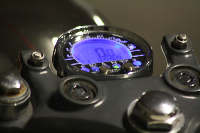
belch_brother said:On the topic of all in one gauges, I went with this option:
http://www.ebay.com.au/itm/Acewell-2853-Digital-Tacho-Speedo-Odo-Fuel-Trip-Meter-/300621516997?pt=AU_Motorcycle_Parts_Accessories&hash=item45fe7050c5
mounted it like this:
Oh and if you are having issue with power consumption I am just about to trial a HID headlight bulb (35w) as opposed to my current (60w/55w). Should give me a couple of spare amps...
http://www.ebay.com.au/itm/120811708851?ssPageName=STRK:MEWAX:IT&_trksid=p3984.m1423.l2649
Hey bud,
Lovin the look of this setup of the dash. Can you possibly post some more shots from above so I can get a better view? Thanks!!


scottyfunj
Been Around the Block
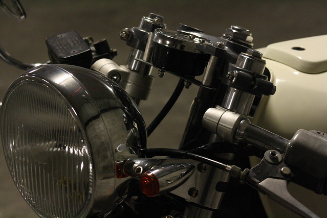
Love the location of your front turn signals.
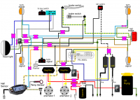
Might be me, but it appears you have a couple issues in your wiring diagram. I am seeing a short to ground. as well as a switch that appears to control the indicator flasher?
Is there a reason for two voltage regulators? Wiring them in parallel like that will help you in the current department, if that is your goal. Perhaps I missed it, but I am not sure that you have a wire for the tail light.
One wouldn't think it, but wiring schematics come in different flavors, & I like what is known as "1-line drawings". It is understood that the components that require a current return path do not have to have that conductor illustrated, so no grounding conductors are shown. Simplifies a drawing.

Good luck with it.
Is there a reason for two voltage regulators? Wiring them in parallel like that will help you in the current department, if that is your goal. Perhaps I missed it, but I am not sure that you have a wire for the tail light.
One wouldn't think it, but wiring schematics come in different flavors, & I like what is known as "1-line drawings". It is understood that the components that require a current return path do not have to have that conductor illustrated, so no grounding conductors are shown. Simplifies a drawing.
Good luck with it.
Dad,
Thanks for the help on this one. Not quite sure (yet) where I've gone wrong, but I'll post up what I was attempting to do and maybe the errors can be worked out...
First, I can't see a short to ground, except maybe the alligator clip? I may have to insulate that some way, but I wanted it in place so that I could hook up a battery and provide power to the bike with out the engine needing to turn over. Mainly to use the oil pump to help drain the oil and to lube up the top end prior to starting, but also in case I needed a bit of juice to get things going (for some reason).
For the switched flasher, the idea behind that switch was to replace the ignition. Black wiring is switched +12V on Hondas and would normally be after the ignition switch, which I no longer have. Still look OK?
Finally, I am very interested in this one-wire idea of schematics, because I've spent a bit of time altering the harness to get rid of as much ground wiring as possible. I've just used the frame, instead. In that type of diagram, how do one represent a switched ground like I have for my headlight (switching the ground instead of the +12V allows me to turn off the high beam and the low beam at the same time)?
Rather than hanging another rotor way out there where it will whip and potentially break off, how about a modern inside out alternator from a different bike. Check out say a SV650 or small GSX/R . Maybe even Ninja 250. What you want is something with higher output that fits close to the crank. Modern rare earth magnets are much stronger than out old rotors.
Have you spoke with Kevin at Motorcycle electrics in CO to see if he can rewind the stator for a higher output. He did a couple of TZ coils for me in the past and they were a huge improvement on stock. If it needs stonger magnets, he can probably make some suggestions.
Have you spoke with Kevin at Motorcycle electrics in CO to see if he can rewind the stator for a higher output. He did a couple of TZ coils for me in the past and they were a huge improvement on stock. If it needs stonger magnets, he can probably make some suggestions.
Looked at the rearsets and that sheet steel will tend to flex for sure.
You have lots of upgrade options though. One way is to weld on two straight sections replacing the old passenger footpeg loops and add mounting bosses to those. Then you can add a short bracket to hang teh muffler from. It will look clean and almost like Honda did it.
If you can get away with mounting the brackets just behind the down tube, you could weld a couple of 1" pieces of say 8 or 10mm ID across the frame for the mounting bolts to go through.
I usually aim to mount the pegs at the swingarm line or maybe 1" or so lower and more or less in line with the middle of the tire looking from the side.
Or just make a copy of the flat plate and weld it to the other side of the frame tube and weld in spacer tubes or box the rear face.
Lots of options.............")
You have lots of upgrade options though. One way is to weld on two straight sections replacing the old passenger footpeg loops and add mounting bosses to those. Then you can add a short bracket to hang teh muffler from. It will look clean and almost like Honda did it.
If you can get away with mounting the brackets just behind the down tube, you could weld a couple of 1" pieces of say 8 or 10mm ID across the frame for the mounting bolts to go through.
I usually aim to mount the pegs at the swingarm line or maybe 1" or so lower and more or less in line with the middle of the tire looking from the side.
Or just make a copy of the flat plate and weld it to the other side of the frame tube and weld in spacer tubes or box the rear face.
Lots of options.............


