CB550 78' "KUBATON" cafe/brat type

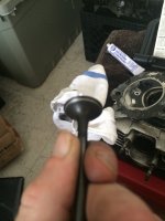
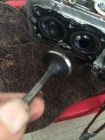
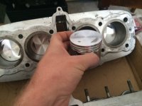
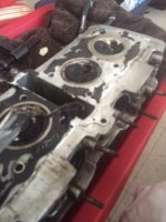
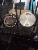
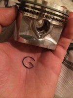
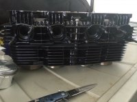
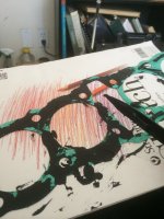
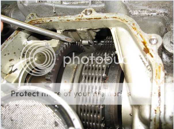
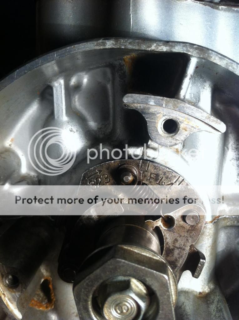
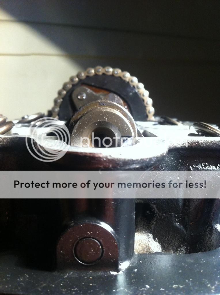
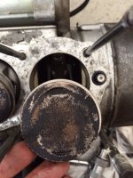
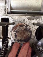
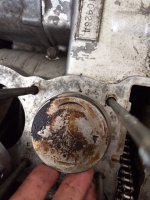
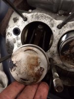
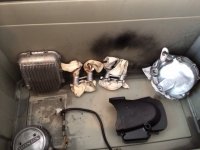
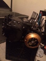
I don't have an accurate measuring device (cylinder or bore gauge) to measure the bores or cylinder heads. Can get my hands on a caliper gauge but don't think this will be accurate enough. Rings seem normal. No weird shit going on, double checked them to see if they were facing up the right way. All are spaced with gaps at the different places correctly, as far as I can tell. It amazes me how cool an actually simple these engines are. What do you think guys? Whats my next step? The following are the piston heads starting with #4. Keep in mind all of these heads where cleaned less than 6months ago, more like 4. I think the mannor in which they are burning (the heads) indicates something but I don't have the experice to guesstimate it.

THANKS AHEAD OF TIME FOR YOUR OPINIONS AND HELP!
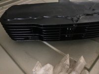
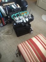
 

Attachments

  • 10.JPG
    10.JPG
    66.6 KB · Views: 790
  • 11.JPG
    11.JPG
    73.2 KB · Views: 792
  • 12.JPG
    12.JPG
    72.4 KB · Views: 789
  • 13.JPG
    13.JPG
    58.6 KB · Views: 798
It sounds a like a combo of rings not sealing in a glazed bore. I'd be tempted to ship the cylinders to someone like Bill Bune in Anoka MN or find a local shop that can bore them to match that Big Bore kit.

While that is happening, pull the valves one cylinder at a time and lap them with fine lapping paste. It would be better to have all the valves and seats SERDI cut but that can get expensive - but no lapping and they just seal way better.
 
Can any one tell me if this looks right? Are the two wheel ends in the correct spots?
 

Attachments

  • image.jpg
    image.jpg
    1.4 MB · Views: 262
Can't quite tell from the pic, but is that smaller, upper roller sitting in front or on the edge round plate? I believe the roller should run on the edge of the plate, not in front. But I cant quite tell if it's in front, or in the recess.
This is from a '75 550K, not 100% if they're the same, but might help you out.
IMG_0837_zpsc76e2f3c.jpg
 
So I've done allot since my last post. Disassembled the lower engine completely and have painted it all. Also put in new spring and shift plates in the clutch. I have to say that splitting the crank case was the most daunting thing I've done so far mechcanicaniclly. Really crossing my fingers as to how everything went together. But had no major issues and everything fit like a puzzle. I was surprised at how clean everything thing was. A bit of dirty oil pockets but that's about it. Shifter looked good and not allot of wear anyplace. Started to put the engine covers on with the new polished allen bolts ad it looks awesome. Good to finally see some work paying off too. Also received a bunch of parts in the mail in the past week. Overbore pistons, clutch plates and new front brake assembly came this morning from Japan. Got the new tail piece aswell. Its a bit bigger than I pictured and I didn't think completely through how I was going to finish, upholster and seam the thing so I may end up not using it. If anybody wants it PM me and i'll sell it cheap (like $15, pic below). I was also able to spray down my pipes with rust converter. They look pretty crappy and are gonna take allot of work to bring em back to life but found no holes or compromised areas (so far). Sanding them down is on tomorrow mornings agenda. Next after I get that squared will be the valves. wish me luck. Any input you have is welcome.
 

Attachments

  • 25.JPG
    25.JPG
    49.5 KB · Views: 739
  • 24.JPG
    24.JPG
    52.6 KB · Views: 714
  • 23.JPG
    23.JPG
    48.3 KB · Views: 714
  • 22.JPG
    22.JPG
    55.1 KB · Views: 713
  • 21.JPG
    21.JPG
    49.9 KB · Views: 732
  • 26.JPG
    26.JPG
    51.1 KB · Views: 717
Anyone have any suggestions on tires? Getting to about the time I need to be thinking about them as shipping a large item here takes awhile. And I need to get it outta the way before I blow through my whole budget for this thing. Something it the not so expensive range ;) Also (and I know this is a dumb question) I'm thinking about painting my rims with the spokes attached. What are the draw backs to this. I realize that it'll be a bitch to remove a spoke after but that's not really something I'm worried about. I'm leaning this way because my workspace is so limited. Anybody done it? Pros/cons?
 
Guys I'm in the middle of my valve job and need a little guidance. I'm using fine grinding paste and a suction cup thingy to grind and seat my valves properly. Take a look at the pic. Am I creating enough of a "new" surface? Is the metal line that's being created big enough/normal or should I be looking for a larger coverage (edge to edge)?
 

Attachments

  • image.jpg
    image.jpg
    838.1 KB · Views: 282
Second question, as I'm pulling the valves I'm finding all the larger head ones (intake?) have clean rims on valve stem heads (see pic). While all the smaller head valves (exhaust) are dirty with no clean metal line on them and all need re-seating/cleaning. What can I infer from this? It's seems like it would be a huge clue as to what caused my running issues. Thanks ahead of time
 

Attachments

  • image.jpg
    image.jpg
    955 KB · Views: 262
Hey, I'm up to the same spot at the moment, I'm no expert, but here's what I've gathered so far. Hopefully someone will correct me if any of that's wrong. Some people say not to lap these valves at all, due to heat/hardness treatment they were made with. But you'll find plenty of threads of people having done so.

I cleaned my valves up with a brass wire wheel on a bench grinder, that way you can see what the faces are like. My exhaust valves looked horrid, caked in carbon, but cleaned up well, and the seat surface looked fine. If there's any serious pitting they might be cactus. You also need to check the seats in the head. If they look average, they'll probably need recutting. There is specs in the manual for the width of the seat.

If there's no serious pitting, rust or dings, from my understanding, you just want to lap enough, to mate the two surfaces evenly, so they seal and don't leak. Less is probably better.
To check that they seal, you reinstall the valves& springs, etc in the head, then pour something like kerosene in, and see if any seeps through the valves.
 
ok lots of progress recently. I lapped all the valves with fine grind. and did a water test and they are all sealed up tight. I really advise buying an actual valve spring clamp/remover if your going to do this. It just makes the work so much easier compared to the "make your own tool trick" or diy tricks. Cleaned all the old gasket reminates and crud off with airplane cleaner a plastic fine edge paint remover and elbow grease. It took forever but im very happy with the results. The past two weeks I've had my cylinders out at a local machine shop. Was going to send them to the mainland for the work but then realized when I was at the post office how much it was actually going to cost me to ship these things. The machine shop I went to surprised me, answer all or most of my questions before I asked them. The work turned out nicely too. Pics are attached of the new over pistons and bored cylinders. They took them to 61.5 to accommodate the new pistons. This should bring my displacement/cc's to roughly 605. I painted both the cyclinders and valve head today and they are curing till I can mess with them tomorrow. I'll be setting the rings to the new pistons tonight and attaching them to the cranks. I still have tons of work ahead of me but I feel like I've finally "reached the top of the hill". Yes I'm way over budget and my planned dealine was yesterday but I really happy with how its turning out. So next up I'm going to piece back together the top end without the gaskets, glue or screws. Just to make sure everything's ready to go and get and stop me from making any stupid mistakes when I do the final reassemble. After that its on to the frame, tires, forks and seat. Basicly lots more paint, new brake system and the fun stuff is about to happen!
 

Attachments

  • 66.jpeg
    66.jpeg
    103.9 KB · Views: 739
  • 666.jpeg
    666.jpeg
    47.9 KB · Views: 775
  • 6666.jpeg
    6666.jpeg
    52.6 KB · Views: 776
Guys how the F$&@@;;;:(!?;() do these little circlips work?! Never seen one like this before. It's the little clip that holds the piston pin in place on either end. I got two in with no problem and have been stuck trying to get the third in for an hour and a half. Tool recommendations? Tricks? Please before I start whipping my new pistons at the walls
 

Attachments

  • image.jpg
    image.jpg
    843.7 KB · Views: 244
  • image.jpg
    image.jpg
    948.1 KB · Views: 247
grab the inner tail with needle nose
insert end tail of circle in groove
rotate it in place so inner tail is vertical :)
 
Hey dude, just to touch back on the valves, I think the exhaust side would be more dirty because it has "dirty" air flowing past it. The intake valves should only see air/fuel passing through and then closing the chamber up when it ignites. The exhaust valves have the spent air/fuel moving past them. Not sure about the small band of material that cleaned up, I'd lap all the valves and compare. If one is awry from the others, you generally know how it "should" be. Looks like you're making good progress and learning a lot!
Shags
 
Anyone know a good source for valve spring keepers for a cb550? Or a similar replacement model. I'm coming up with nothing on eBay. Somehow miss place a set of them. Tearing my work room apart to find them but not hopeful. Lmk. Still had a lot of progress today even with that setback. Set the rings to pistons. Finally figured out that those silly G clips work allot easier when the piston pin is in so they can't slip through. To set the pistons into the new bores I turned the engine so 2+3 where at top dead center. Then put pistons 1+4 into their cylinders with the hole for the piston pins exposed on the bottom. I slid 2+3 in their cylinders, was easier than doing all four and they are close together so I didn't have to do the seasaw game with the head too much. Next I pushed the head down far enough to reach and attach 1+4. Wasn't easy and took way too long but alternatives with out some sort of sleeve or a second pair of hands would've taken forever. For now on I will officially refer to those G clips as *oddamit clips tho. I didn't push it all the way down yet as I still have to put the chain guide back in. There's a pic of the paint hod on the cylinder and head. They shine, really happy with them. Going to go back over the engine with a quick layer of paint once the cylinder head is all the way on tho. If anyone knows a source for those keeper or wants to trade for something lmk please. I need them quick. I found out today that I'll be headed back to the mainland at the end of the month and that means I need this back together like now.
 

Attachments

  • image.jpg
    image.jpg
    1.5 MB · Views: 247
  • image.jpg
    image.jpg
    1.4 MB · Views: 242
  • image.jpg
    image.jpg
    882.3 KB · Views: 244
  • image.jpg
    image.jpg
    967.7 KB · Views: 237
http://www.dimecitycycles.com/vintage-cafe-racer-caferacer-bobber-brat-chopper-custom-motorcycle-engine-parts-honda-cb-cl-valve-keeper-14-1750.html

http://4into1.com/vesrah-valve-keeper-cc-1002/

You might want to leave a gap of an inch or so between the jugs and the cases so you can get the cam tensioner back in. It wont seat properly in the grove otherwise. You'll have to tip the motor up to check. See what I mean in this photo.
ScreenShot2014-08-30at71622pm_zpsd2634017.png
 
Thanks Bootsey! Ur a gem. Didn't even think dcc would carry something like that. Oh, I forgot. I wrapped the painted pipes today. Wrapping 4into1 pipes is like doing algebra with snakes. Turned on nice tho. I'll throw up pics next time. Oh just a friendly reminder, wear pants while wrapping pipes. Trust me
 
Having issues getting the cam chain back on the sprocket/cam assembly. Its been holding me up for a week. Need some insight on how to get it back together. I've watched this https://www.youtube.com/watch?v=dDZS4ZZRyik and am doing it this way with the chain to the left of the sprocket. I can get the chain on to the sprocket and lined up with the cam to screw it together (sprocket to the cam) but they are not close enough. I am worried that if I just man-handle it together and force the screw ill brake the cam where it screws (which ive done before on a different engine). Any tips appreciated! Im completely stuck, even contemplating lugging the engine to a shop tomorrow if I cant get it done tonight. help!!!!!!
 
I've felt you're pain, once you get it right, it all seems simple.

If you've got the advancer plate on the RH end of the crank, rotate the crank so it is at marking T.1&4.
Like this. This is where cylinders 1 & 4 are at TDC.
IMG_1130_zpsb839d1dd.jpg

At this point, the slot in the end of the cam shaft, needs to be parallel to the head surface.
IMG_1129_zpsdf6a48c7.jpg


First up, sprocket needs to be loose from the camshaft. See the mickey mouse sort of ears in the sprocket? You use them to get enough clearance to get the chain on.

Also, undo the locknut on the camchain tensioner, and turn the screw clockwise(I think), to take the tensioner blade out of the way. Then tighten to locknut. This will give you a bit more clearance with the chain.

Feed the camshaft through the chain, the slotted end, to the RHS of the motor. Then feed the sprocket on from the LHS. Try to set the slot in the cam parallel, so you don't have to jump a tooth in the chain later to get the correct timing.
It takes a bit of time, but you'll get it.

Follow this link, there's a better explanation down the page a little.
http://forums.sohc4.net/index.php?topic=369.msg57914#msg57914
 
Thanks Boot's. Have been all that except for putting tension on the TENSIONER! I'd even backed the nut on the tensioner all the way without thinking and adjusting the screw as well. Going back in later after my blood pressure returns to normal, hopefully that provides the slack I need.
 
Back
Top Bottom