
We noticed you are blocking ads. DO THE TON only works with community supporters. Most are active members of the site with small businesses. Please consider disabling your ad blocking tool and checking out the businesses that help keep our site up and free.
You are using an out of date browser. It may not display this or other websites correctly.
You should upgrade or use an alternative browser.
You should upgrade or use an alternative browser.
cb360 wiring harness
- Thread starter 360noob
- Start date
Question again about wiring...the wire my bike used to have running to the positive terminal on the battery was a big fat sucker, more like a cable actually. Do I need to replace that and keep it in the system or am I good with out it? Follow? It would have been the positive from the battery to the on/off switch...
Thanks gents! Its coming along!
Thanks gents! Its coming along!
shocwav3
Been Around the Block
Sonreir said:Short answer is, "Yes, you do need that big fat wire". I think it's 10 gauge?
Long answer is that it depends on how much current your bike is pulling. Replacing incandescent bulbs with LEDs or omitting certain sections of your wiring will reduce your current draw.
I think I am running a 12 gauge, doesnt seem to be much trouble. But, bigger is always better in those scenarios.
shocwav3
Been Around the Block
andoor said:Just a tip, be careful what wiring diagram you are using as a reference. I noticed little differences between the Honda / Clymer manuals, and also some diagrams I found online. I think it was primarily differences in wire colors.
Andoor,
I agree, I have scene quite a few diagrams with different color leads. Not to mention when I went to my bike, most of my wires were indistinguishable from dirt and years of neglect. That is why I just re-wired it from scratch, it was actually much easier than fingering around with original wiring.
Ok so now my problem is I'm not getting spark and my frame is lighting up my tester...
Is there a way to test the coils to see if they're functioning properly? I feel like thats where my problem is...And are they fairly universal? I've got a cb350 in the back of my garage with coils on it, might I try those?
As usual, thanks for the tips!
Is there a way to test the coils to see if they're functioning properly? I feel like thats where my problem is...And are they fairly universal? I've got a cb350 in the back of my garage with coils on it, might I try those?
As usual, thanks for the tips!
shocwav3
Been Around the Block
dStew said:Ok so now my problem is I'm not getting spark and my frame is lighting up my tester...
Is there a way to test the coils to see if they're functioning properly? I feel like thats where my problem is...And are they fairly universal? I've got a cb350 in the back of my garage with coils on it, might I try those?
As usual, thanks for the tips!
What do you mean the frame is lighting up the tester? Remember that your frame will be grounded so it should have continuity between a positive lead and the frame.
Measure resistance of the coils to see if they are out of range (procedure is in the manual if im not mistaken). Also I had a set that measured fine but once they heated up gave me inconsistent spark.
As long as the primary and secondary resistance is similar from one coil to the next another style coil will work fine, I run xs 650 coils due to there availability and price. Mikexs has them new for around 30 bucks.
Yeah I mean when I touch my tester to the frame, it lights up. That's not the case with the other bike in my garage...I was just trying to figure out if that was normal or not.
So you're using xs coils on your 360? And that works ok? Maybe, I'll just go that route and save me some headache, the rest of everything seems to be working fine, I'm just not getting any spark...
Thanks again!
So you're using xs coils on your 360? And that works ok? Maybe, I'll just go that route and save me some headache, the rest of everything seems to be working fine, I'm just not getting any spark...
Thanks again!
shocwav3
Been Around the Block
dStew said:Yeah I mean when I touch my tester to the frame, it lights up. That's not the case with the other bike in my garage...I was just trying to figure out if that was normal or not.
So you're using xs coils on your 360? And that works ok? Maybe, I'll just go that route and save me some headache, the rest of everything seems to be working fine, I'm just not getting any spark...
Thanks again!
When using the frame as earth(ground) it will light up the tester, assuming the other lead on your tester is touching a positive line, all positive leads need to be isolated from the frame as not to short the set up. I dont know what other bikes you are in the garage but I would bet some dont ground back to the frame...not sure though. I always ground back to the frame becuase it keeps my ground leads short all over the bike.
xs650 coil is a pretty common replacment for the 360, I would assume becuase they are pretty cheap new. Some guys are running Dyna's as a performance upgrade if Im not mistaken.
Hey thanks for posting the diagram, it is what i used to wire my 360! I do have a question reguarding adding a regulator, the oem regulator has 3 wires, I noticed you responded earlier stating to add it between the rectifier and battery. My question is how do all 3 wires get used when adding the regulator to your diagram? I assume that black is ground and the regulator comes between rectifier and battery, does it matter which direction the other 2 wires are added in?
Thanks!
Thanks!
bjbuchanan
New Member
Black isn't ground on these old bikes unless he changed things totally and uses a new color coding
The ground will be green, the power will be black and the white is the power that gets sent out
The black uses battery voltage to sense when to excite the alternator, its like a communicator wire fly
The ground will be green, the power will be black and the white is the power that gets sent out
The black uses battery voltage to sense when to excite the alternator, its like a communicator wire fly
mydlyfkryzis
当有疑问时踢你的敌人在生殖器上,你可以道歉后
If you are using an Onan (John Deere) type regulator/rectifier that has the three connections, the two outer connection hook to pink and yellow that go to the rectifier. That is the A/C from the alternator. The red/white wire on the rectifier goes to the center terminal. That is the regulated DC out to the battery. The green wire gets grounded and you need to ground the new rectifier also, either through the mounting bolt to chassis, or mounting bolt to a good ground.
The original regulator, with the three wires green, black, yellow, is removed and you do not need to do anything to those wires but fasten them so they don't dangle.
Look at my picture Here:
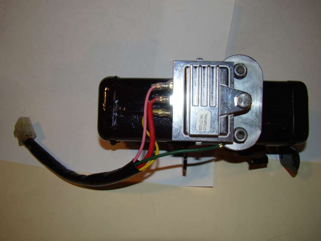
this is for my CB360. Check the build out in my signature....
The original regulator, with the three wires green, black, yellow, is removed and you do not need to do anything to those wires but fasten them so they don't dangle.
Look at my picture Here:
this is for my CB360. Check the build out in my signature....
bjbuchanan said:Black isn't ground on these old bikes unless he changed things totally and uses a new color coding
The ground will be green, the power will be black and the white is the power that gets sent out
The black uses battery voltage to sense when to excite the alternator, its like a communicator wire fly
Not quite right... The 360 has a permanent magnet charging system so the alternator doesn't use any voltage, it only produces it. The white wire is an AC partial circuit that is normally off. When you turn on the high beams, that switch also completes the circuit for the white wire and you get extra charging to help account for the high beam's extra wattage draw.
The stock regulator has a yellow wire, black wire, and green wire (ground). The yellow wire acts like an "input" to the regulator so that it knows how much voltage is being produced by the alternator. As the voltage increases, the regulator will shunt more voltage from the DC side (black wire) in order to keep the voltage levels in range.
mydlyfkryzis
当有疑问时踢你的敌人在生殖器上,你可以道歉后
Sonreir said:Not quite right... The 360 has a permanent magnet charging system so the alternator doesn't use any voltage, it only produces it. The white wire is an AC partial circuit that is normally off. When you turn on the high beams, that switch also completes the circuit for the white wire and you get extra charging to help account for the high beam's extra wattage draw.
The stock regulator has a yellow wire, black wire, and green wire (ground). The yellow wire acts like an "input" to the regulator so that it knows how much voltage is being produced by the alternator. As the voltage increases, the regulator will shunt more voltage from the DC side (black wire) in order to keep the voltage levels in range.
Actually, the Black wire is the DC Battery Voltage reference wire. The regulator actually shunts (grounds) the AC yellow wire to ground to regulate it.
On the later 360's, if you do not have the right pod on/off light switch, Honda connected the white and yellow together under the tank, at the big wire junction. On the older ones, the light switch controls the output. Light off, yellow only, lights on, yellow and white together. the Yellow is about 1/3 output 45 watts or so, the white is about and additional 85 watts or so. Ignition and battery charge can be handled with 40 watts. The lights, added up, need the additional 85 or so. Headlight is 35W/50w, with low beam you get yellow markers up front, 3W each plus tail 3 w, plus brake light can be 7W. Signals are 7 watts each, 2 at a time. Plus the 4 gauge lighting lamps, and intrument indicators (high beam, neutral, signal).
The system has pretty much just enough output to light the lights, spark the plugs, and up to 40 watts to charge the battery when the lights are off and the coils not being powered between points closing and opening.
that's why a 55/60 watt H4 bulb, on an otherwise stock system, puts it on a deficit, as there is nothing left to charge the battery.
The math isn't exact because the numbers aren't exact. this is because the average current draw of the coils varies with RPM, as does the output. At idle, you do NOT have the full 130 watts. The full amount should be available above 5000 RPM. At 9000 RPM, it can put out over 130 watts, but you are going to kill the engine if you race around at 9000 rpm all day.
mydlyfkryzis said:Actually, the Black wire is the DC Battery Voltage reference wire. The regulator actually shunts (grounds) the AC yellow wire to ground to regulate it.
Originally, that's how I thought it worked, too. But I went over the diagram a few times and it looks like the pink wire would be unregulated, which doesn't seem right.


