6v magneto CDI system, head scratcher.

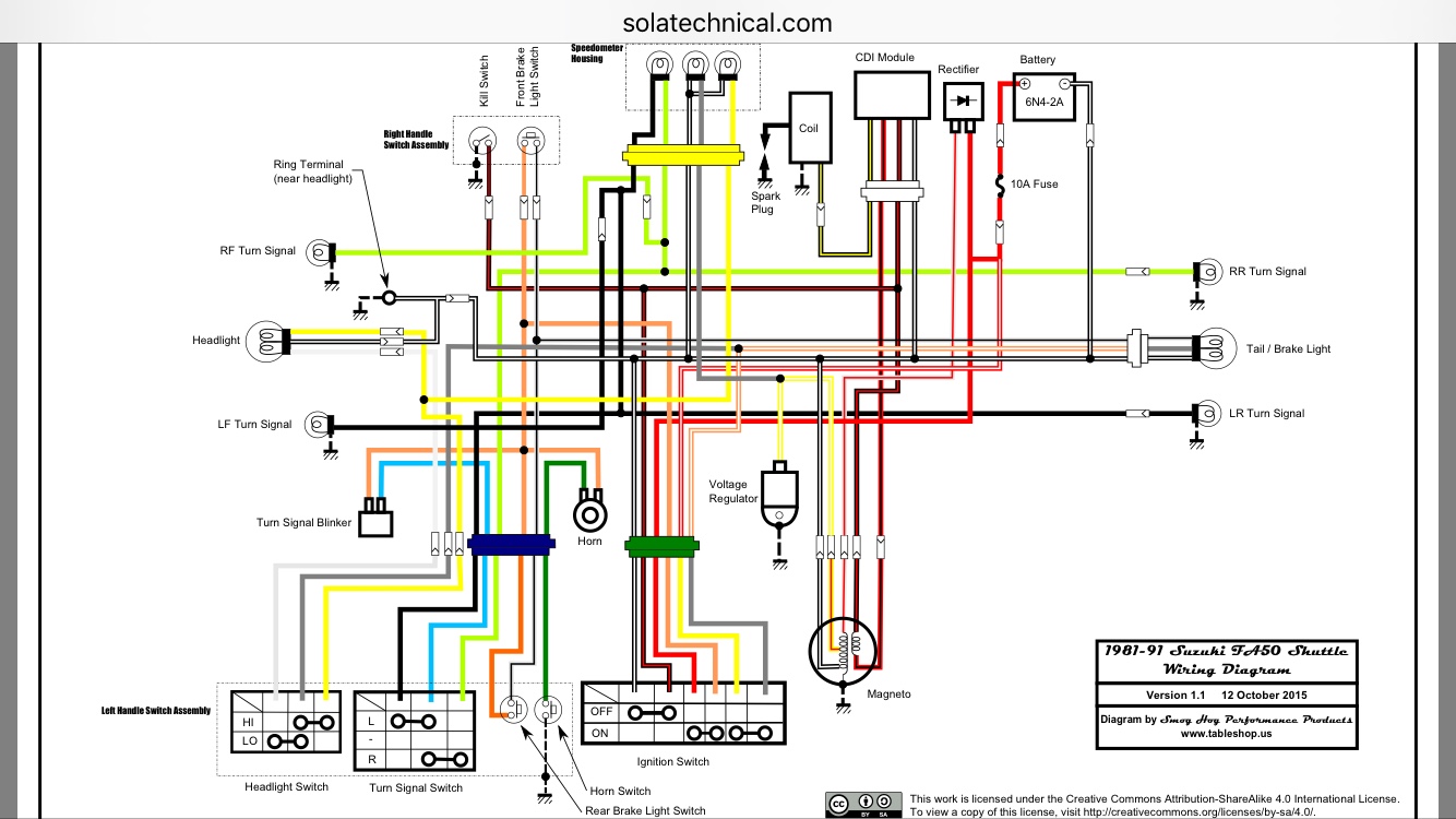
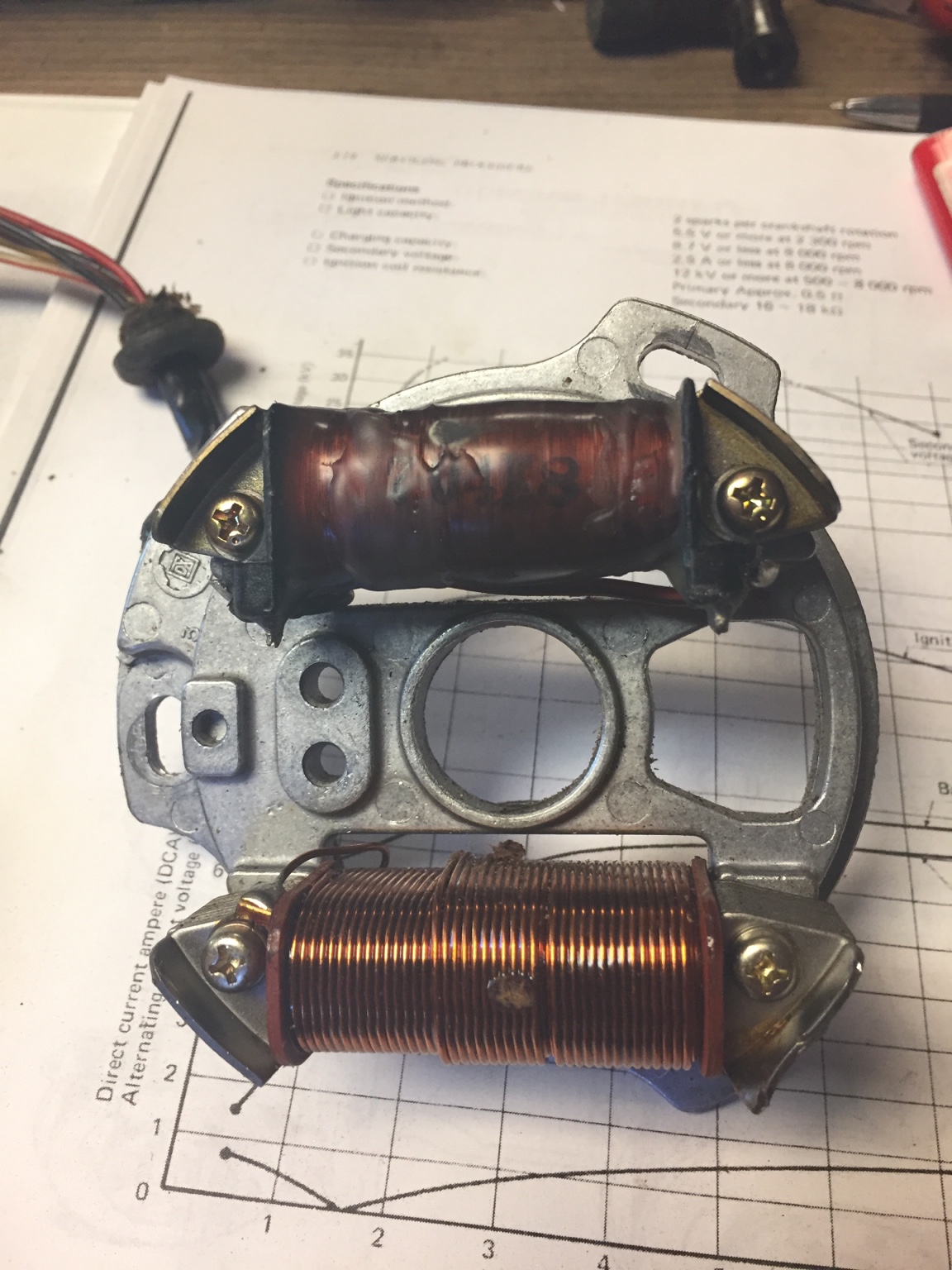
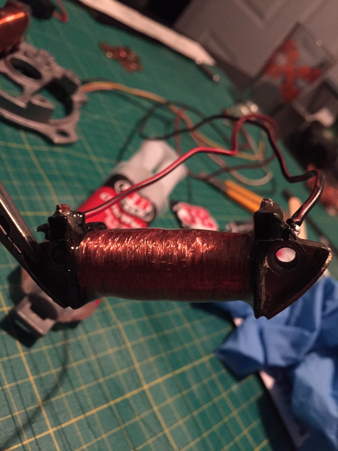
I'd speculate that it's a broken lead either in the windings or more likely where one of the main leads is soldered to the winding wire. They get old and brittle. I have had to get a few TZ generator coils rewound over the years.

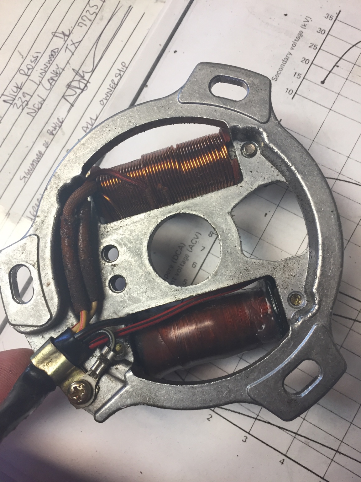
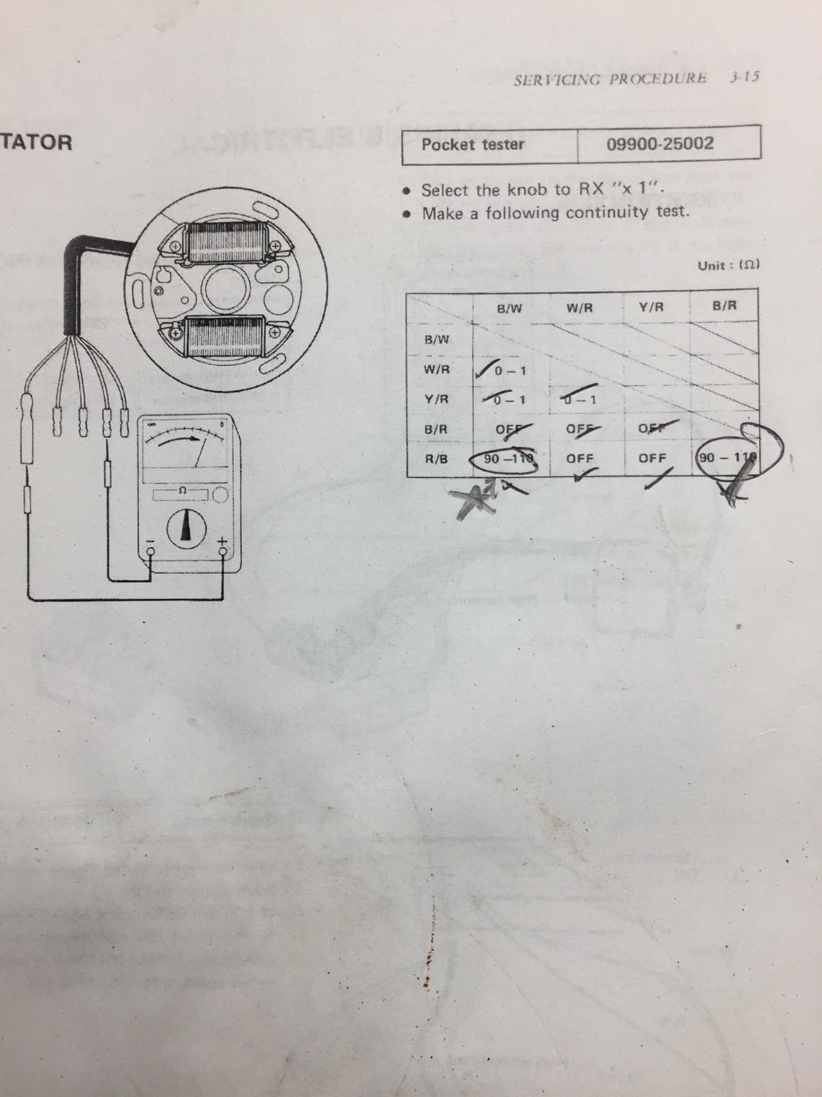
Are those figures in the book for a different bike than the wiring diagram we saw earlier? I am surprised to see a resistance between R/B and B/W on that chart. R/B to B/R yes - that is the ignition coil. That's not how I was reading the wiring diagram.

Either way, if R/B to B/R is open circuit there is a break in there somewhere.
 
4949dffd1945d620ad981c673e93e129.jpg


I just pulled up this diagram for the FA50. I posted an FZ50 diagram earlier, but they are just about the same. In fact, the FZ diagram was closer to the physical wiring than the diagram in the manual was, maybe the changed the harness for the later years. The image above is exactly what I have on the bike.

Anyways, I would like to test the stator with another multimeter, I don't always trust mine.


Sent from my iPhone using DO THE TON
 
I pulled the flywheel and stator. The dang stator looks like it's brand new. All windings are in place and soldered connections are solid.

26691a49127386b9c50991e286453bb2.jpg


26f8dfec376221d7cdbb145efe5df7dd.jpg


It tested open as I said before but it's just not adding up.


Sent from my iPhone using DO THE TON
 
If it is "open" then there's a break inside somewhere. Unfortunately, re-winding can be expensive. IS there a pit bike electronic CDI that could be used instead?
 
teazer said:
If it is "open" then there's a break inside somewhere. Unfortunately, re-winding can be expensive. IS there a pit bike electronic CDI that could be used instead?

I'm not sure, if I could cross reference parts but from browsing eBay it looks like some newer 50cc bikes have similar stator setups for way cheaper money, and most of them come with a stator and CDI unit.


Sent from my iPhone using DO THE TON
 
If the crank taper is the same as a Honda, which it probably is, then any pit bike/clone could be modified to fit. If the taper is different, it should be possible to cut a new taper.

Many bikes have the same taper so for example, Yamaha TZ/RD, Honda RS125/CB77/CB160, Suzuki T20 - all the same taper angle. Larger Suzukis, like a GT750, not so much.

If you don't need lights, a race only unit will work, but if you want charge, a street oriented source bike (Honda clone from China) will probably work.
 
You should just rewind them yourself? It's really not that hard and the magnet wire can be bought cheaply off eBay.
 
teazer said:
If the crank taper is the same as a Honda, which it probably is, then any pit bike/clone could be modified to fit. If the taper is different, it should be possible to cut a new taper.

Many bikes have the same taper so for example, Yamaha TZ/RD, Honda RS125/CB77/CB160, Suzuki T20 - all the same taper angle. Larger Suzukis, like a GT750, not so much.

If you don't need lights, a race only unit will work, but if you want charge, a street oriented source bike (Honda clone from China) will probably work.

I will do some research and see if I can find something that will work. What exactly do you mean by "crank taper"?


deviant said:
You should just rewind them yourself? It's really not that hard and the magnet wire can be bought cheaply off eBay.

I have heard of people rewinding themselves, and that seems like a cheaper option. Maybe I will read up and see what I can find. Don't really have anything to lose if I muff it up.
 
What I meant was if you change the whole ignition system, the rotor has to match the taper on the end of your crankshaft. Here's a couple of links on the subject plus top possible replacement parts.


http://www.mopedarmy.com/wiki/Crankshaft_ignition_taper

http://www.mopedarmy.com/wiki/Lapping_tapered_crankshaft_and_flywheel_surfaces_for_good_no_slip_bond

http://www.practicalmachinist.com/vb/abrasive-machining/grinding-crankshaft-flywheel-taper-275487/

http://www.practicalmachinist.com/vb/attachments/f44/95701d1388763746-grinding-crankshaft-flywheel-taper-photo-11-.jpg

http://www.dhz.com.au/buy/stator-magneto-lifan-ducar-kick-start-engine-light/ENP-27.LF125

http://www.ebay.com/itm/IGNITION-STATOR-MAGNETO-PLATE-125CC-PIT-BIKE-XR50-SDG-SSR-107-110-125-M-IS01-/360103355433
 
I rewound the primary coil, and ended up with about 90 ohms higher than the manuals range. Should I desolder and unwind some of the the wire or will it work as it is? Resistance in the manual is 90-110 ohms.

c987f362ac28a3636d409d127f196913.jpg


Sent from my iPhone using DO THE TON
 
Generally, the higher the resistance, the lower the voltage output.

You won't hurt anything just by trying it out, though.
 
Before I start unwinding, I noticed something incorrect. The factory service manual states there should be a resistance of 90-110 between Red/Black and Black/red, shown in picture above, which is the primary winding itself. There should ALSO be a resistance of the same value (90-110) between the R/B lead and the B/W (grounds directly to the stator mounting plate frame), and this is currently an open circuit.

d6f7ce45d3247f6b0a1fb93359c52bb9.jpg


In order to achieve proper resistance, does this mean that the beginning of the winding (to which R/B is connected) should also ground directly to the mounting plate? I can't think of another way to achieve resistance between the two. I thought the windings were supposed to be isolated?


Sent from my iPhone using DO THE TON
 
Grounding a circuit doesn't change it's resistance. If you ground the red/black or the black/red then the system will not work. Grounding either of those wires is how the kill switch stops the engine.

According to the diagram of the FA50 you posted earlier, I wouldn't expect to see continuity between the B/W and R/B.
 
Ok, I do believe that is the manuals way of saying "test this with the stator installed and the kill switch off and there should be continuity" aka the kill switch is working. I unwound until I hit just about 110 ohms, soldered everything back up and put a coat of epoxy on to hold everything in place.

938a6ab7395683e746596222a7075480.jpg


9827df6b97d9a0a640c19eb922653aed.jpg


Sent from my iPhone using DO THE TON
 
Back
Top Bottom