I recently resurrected this SS350 from perhaps decades of storage
All is well except the battery is not being recharged
I have a bar mounted volt meter to verify this
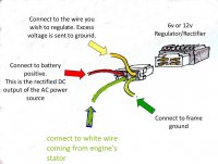
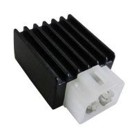
The original R/R was toast so I am using one of the pit bike units as shown below
The 'Macchi has two alternator coils - one for the headlight and one for everything else
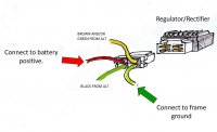
The HL coil leads are black and green, and the other coil is black and brown
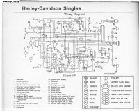
Per the original schematic, when the HL is on, the brown and green are spliced, essentially making both coils parallel and supplying the extra amps
At idle, there is about 9 volts AC coming from both coils but it increases to over 15 v with increased rpm
I have a three position switch that turns on the ignition in one position and ignition and and HL in the second position
This allows me to kick start it and then turn on the headlight after it's idling
I have a jumper between brown and green so that both coils are feeding the R/R
Did I do something wrong here? Did I ruin the R/R by sending it too many AC amps?
Should I use a separate R/R for the lighting coil?
All is well except the battery is not being recharged
I have a bar mounted volt meter to verify this
The original R/R was toast so I am using one of the pit bike units as shown below
The 'Macchi has two alternator coils - one for the headlight and one for everything else
The HL coil leads are black and green, and the other coil is black and brown
Per the original schematic, when the HL is on, the brown and green are spliced, essentially making both coils parallel and supplying the extra amps
At idle, there is about 9 volts AC coming from both coils but it increases to over 15 v with increased rpm
I have a three position switch that turns on the ignition in one position and ignition and and HL in the second position
This allows me to kick start it and then turn on the headlight after it's idling
I have a jumper between brown and green so that both coils are feeding the R/R
Did I do something wrong here? Did I ruin the R/R by sending it too many AC amps?
Should I use a separate R/R for the lighting coil?