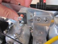
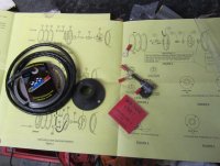
I found these neat mini waterproof switches, which I'll use for the horn and hi/low beam, just managed to fit them next to the ignition switch, which will keep the wiring out of sight.
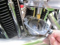
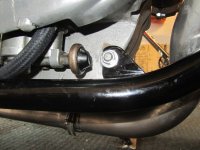
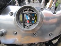
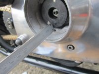
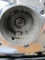
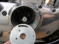
Hit a couple of small problems along the way, damaged case threads and I cant remove the old broken oil pressure switch to fit a replacement. Its in a tight spot and the nut has been rounded off some time in the past and it doesn't want to come off. I should've removed it before the motor was back in the frame, but I didn't want to risk damaging the new pressure switch when fitting the engine. I may have to remove the oil pump, which could open another can of worms..we'll see.
Hit a couple of small problems along the way, damaged case threads and I cant remove the old broken oil pressure switch to fit a replacement. Its in a tight spot and the nut has been rounded off some time in the past and it doesn't want to come off. I should've removed it before the motor was back in the frame, but I didn't want to risk damaging the new pressure switch when fitting the engine. I may have to remove the oil pump, which could open another can of worms..we'll see.
")