SR250 Brat/Street Tracker - First Build (aka Little Trouble Kid)

chiel

New Member
Hello fellow builders,

I've been following some builds for quite a while and learned a lot from them, so i was thinking i could contribute and also use this build to learn even more. Short introduction: I'm a 26-year-old Belgian graphic designer and had a passion for bikes ever since i was a little kid. My dad used to drive superbikes and i dreamed about doing the same thing, but my mom would never allow it, so for years i forgot about this passion.
About 3 years ago my father in law decided it was time to learn how to ride a motorcycle and i was hooked again. I got my drivers license, bought a brand new bike and commuted to work on a daily basis. Best thing i ever did.

The bike is fantastic, but there were 2 drawbacks. It was full of new technology, which i didn't know anything about so had to go to the dealer for every small thing which is costly, time consuming and doesn't help you in the long run (when you're stranded somewhere on the side of the road).
The second drawback: when the weather gets colder out here they love to use a lot of salt on our roads to keep you on them. Since i didn't look forward to hose down my bike after every commute, and it would hurt my eyes too much to see my bike getting eaten away by this salty mess i decided to buy a 'winter bike'. A cheap, old, beaten-up but reliable motorcycle i wouldn't be afraid to (ab)use, and learn me some mechanics/metalworking. That's what i would tell myself, but it was an excuse to get a shiny retro bike like all the cool guys on here seem to have.

After a quick search i settled on a '94 Yamaha SR250 with only 19.000 Kms (± 12,000 Miles) who seemed to be in a decent shape. The previous owner slapped on a different tank (from an XS400), changed the seat (to something weird and home-made) and tried to 'café it' (his words). I even got the original parts with the bike and all i had to change was a dead battery. In retrospect, i overpaid and the bike was in a far worse condition than i had expected. Bought it in the first half of November, got it insured within the week en was thinking i would only mis a week or two of commuting with the bike, but currently i'm still fixing things that seem to break when i'm working on something else.

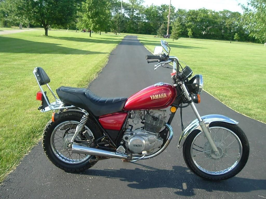
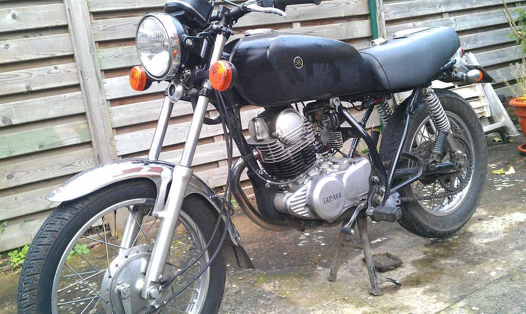
Well, long story short: judging by the old tank this is what she must have looked like 20 years ago:

11842944363_daa3e1ea3f_b.jpg


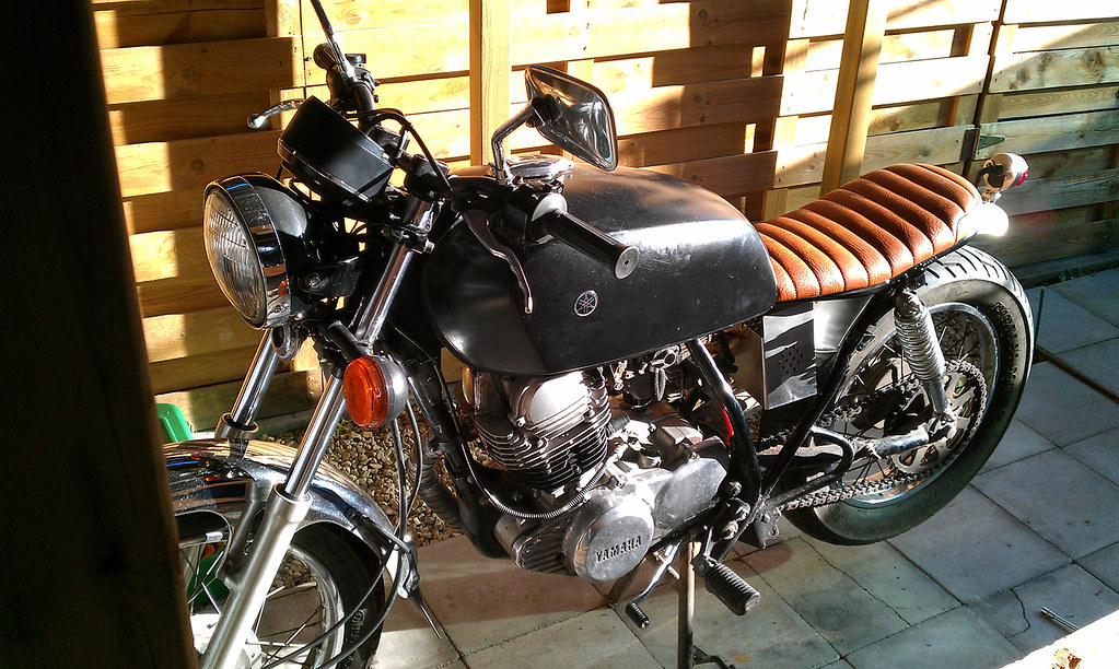
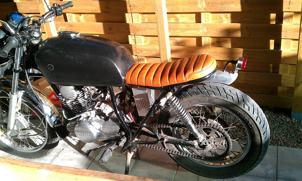
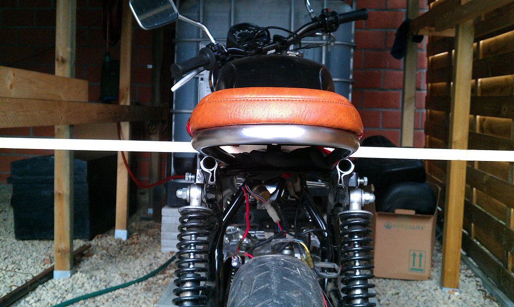
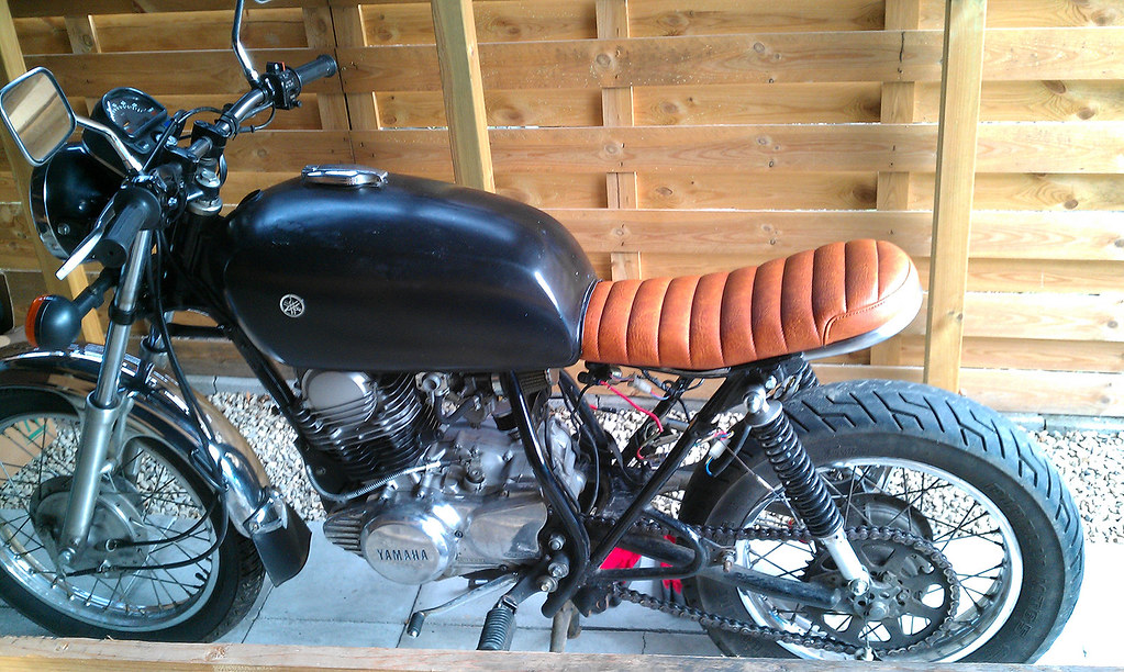
This is her the day i brought her home:

11842652535_a4315ec4e7_b.jpg


11842933933_2685bb8365_b.jpg


11842644355_224bd51a97_b.jpg


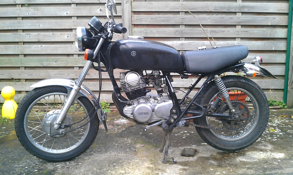
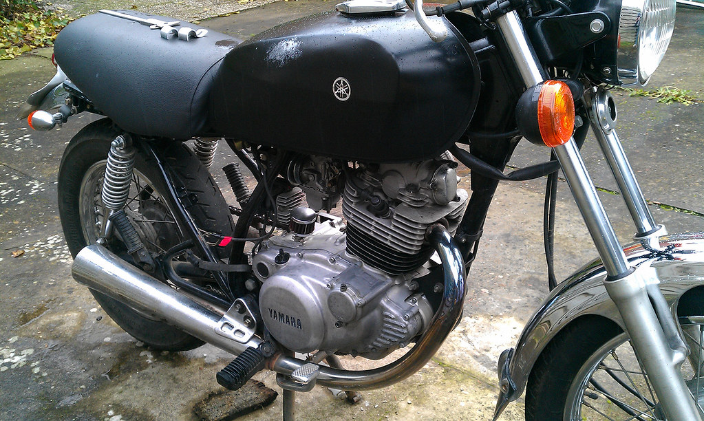
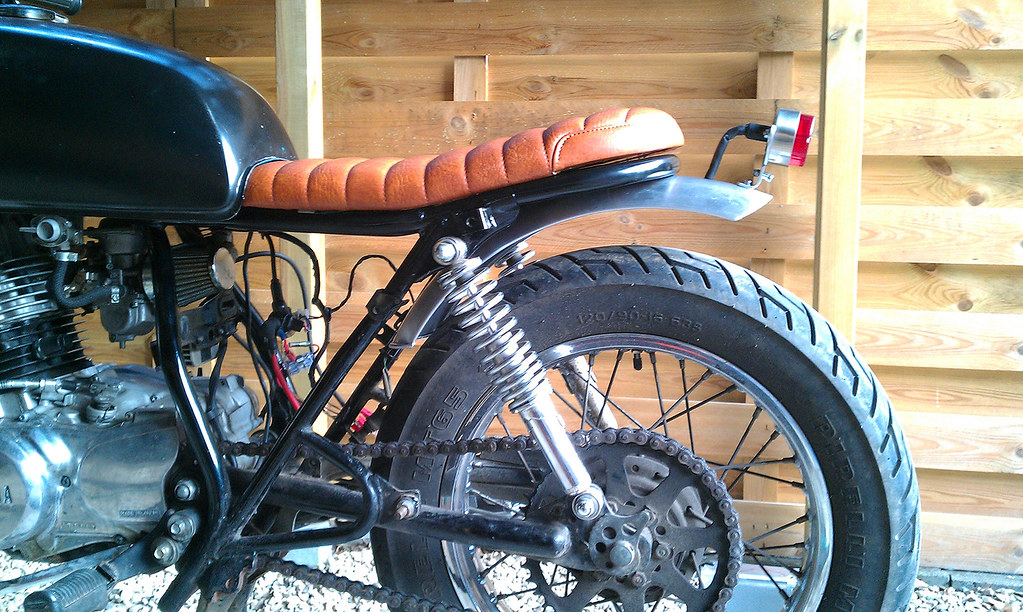
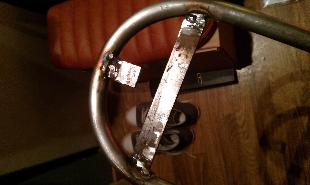
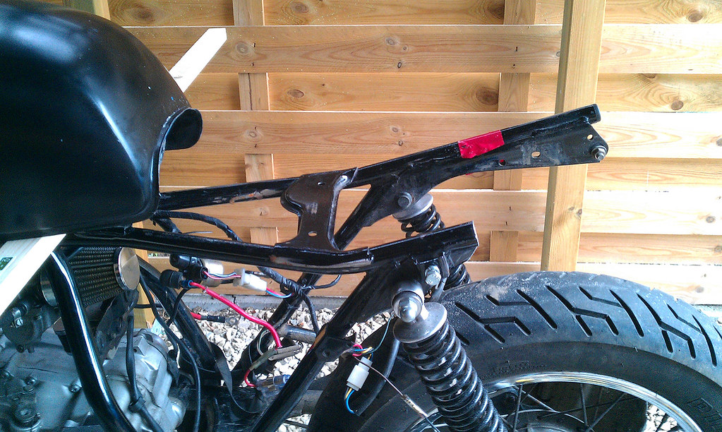
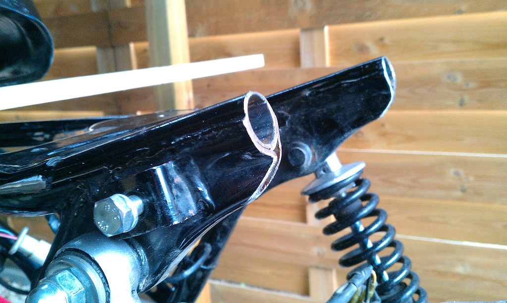
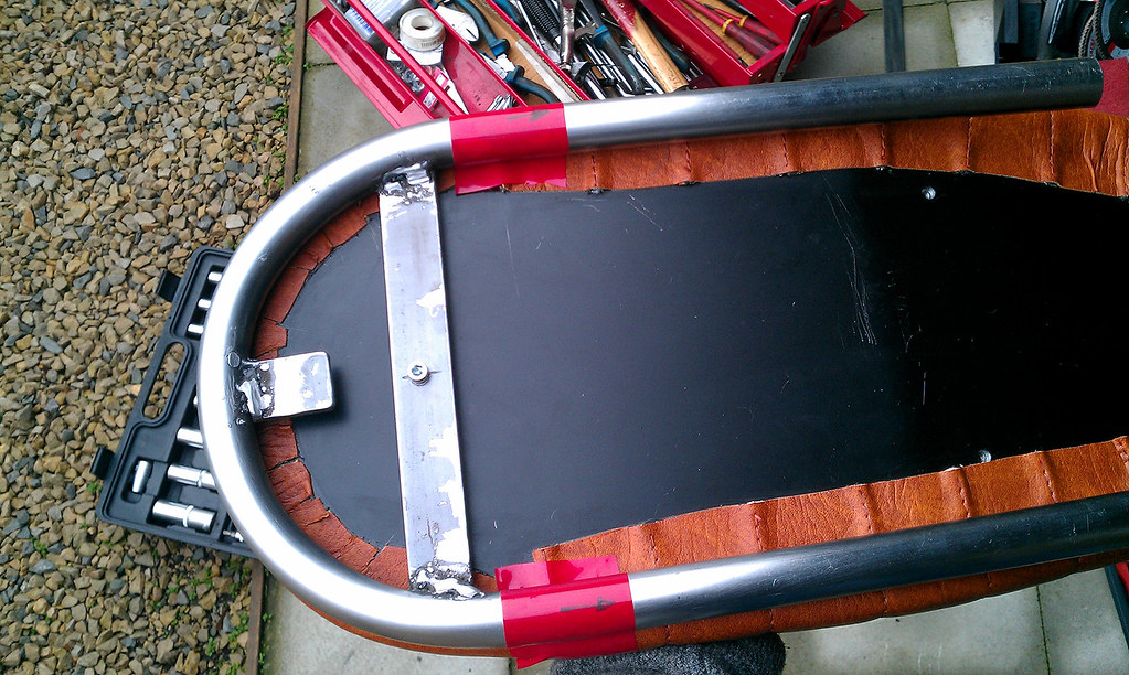
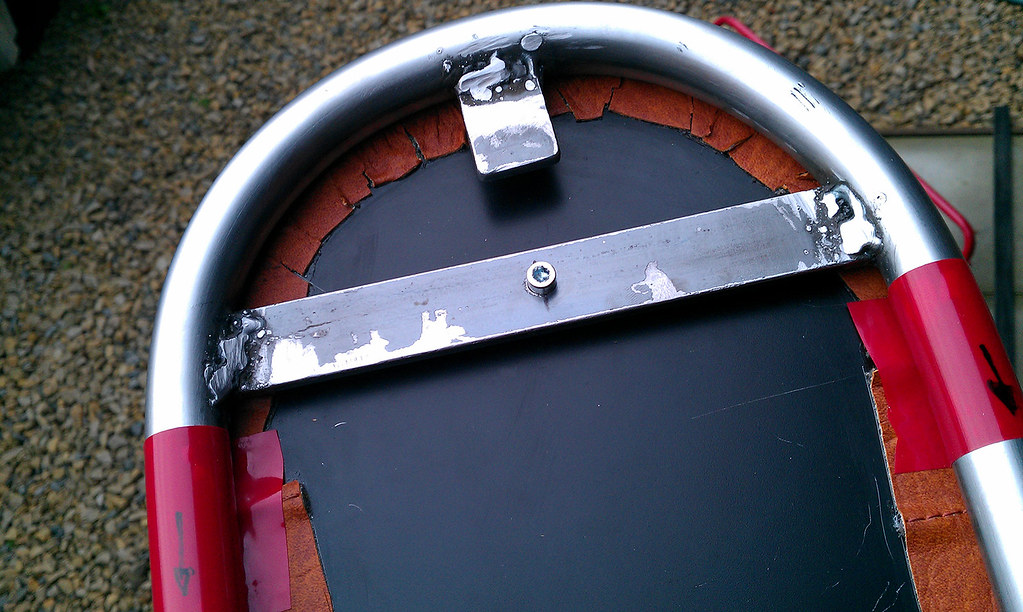
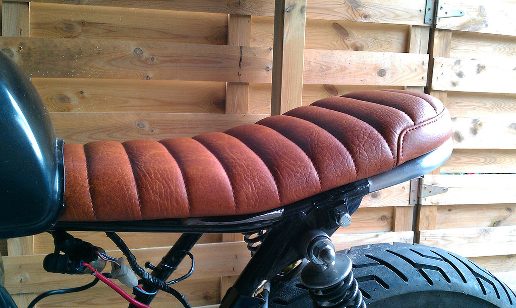
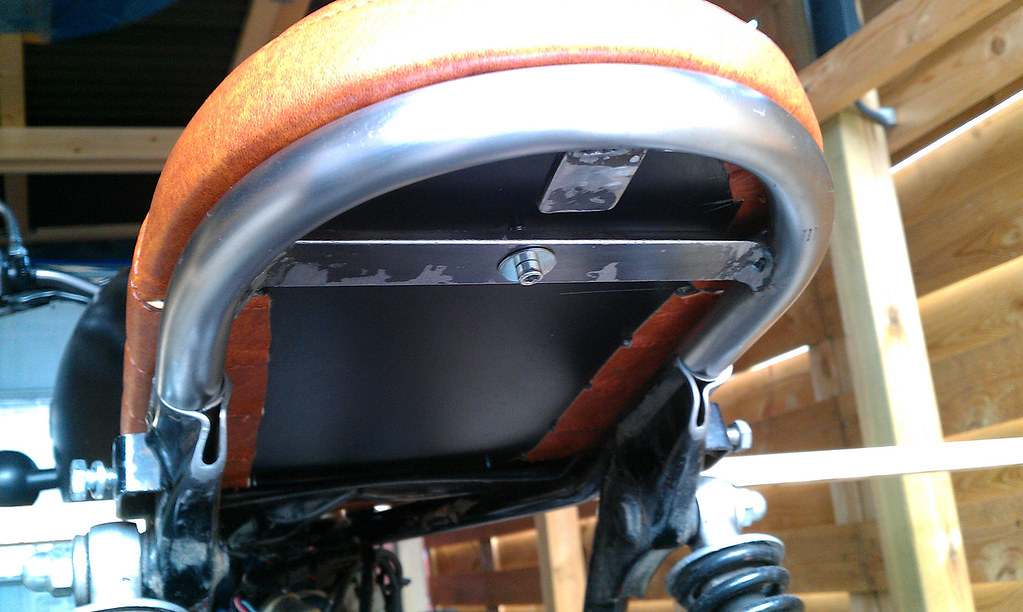
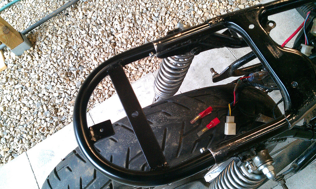
(this is where i started noticing some problems and a crappy seat job/subframe hack the previous owner did)

11843432326_016b8e3224_b.jpg


11842922503_90408c68bb_b.jpg


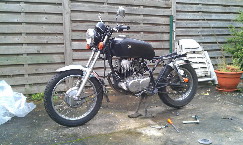
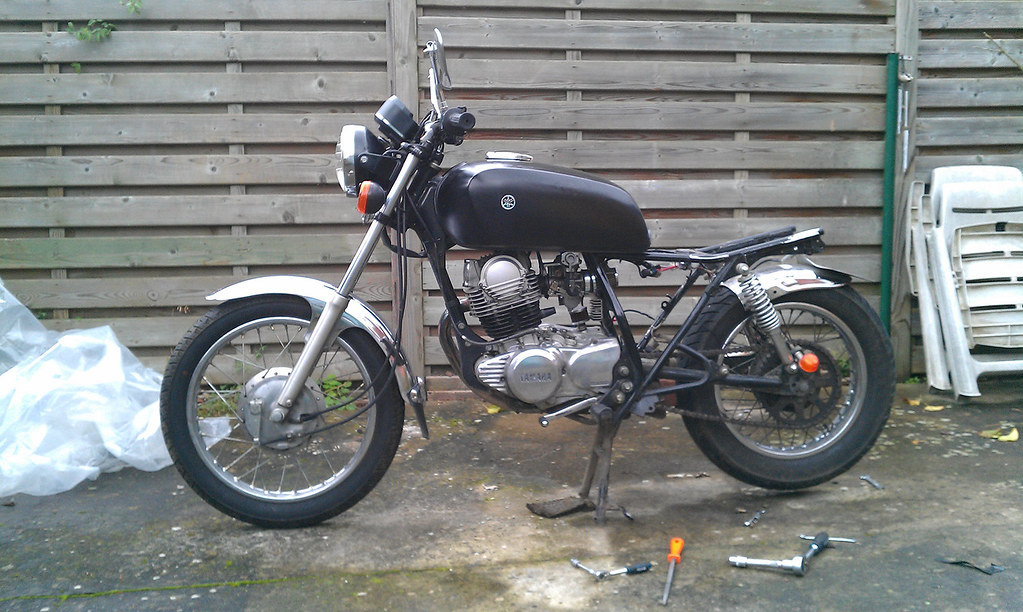
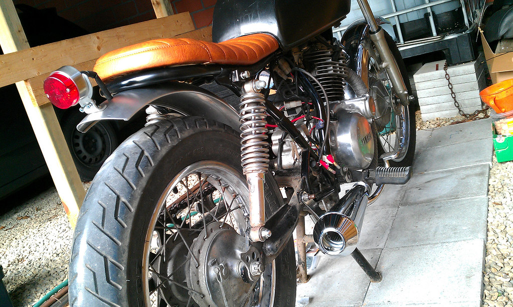
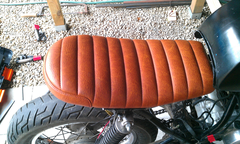
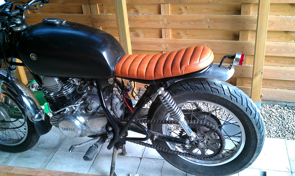
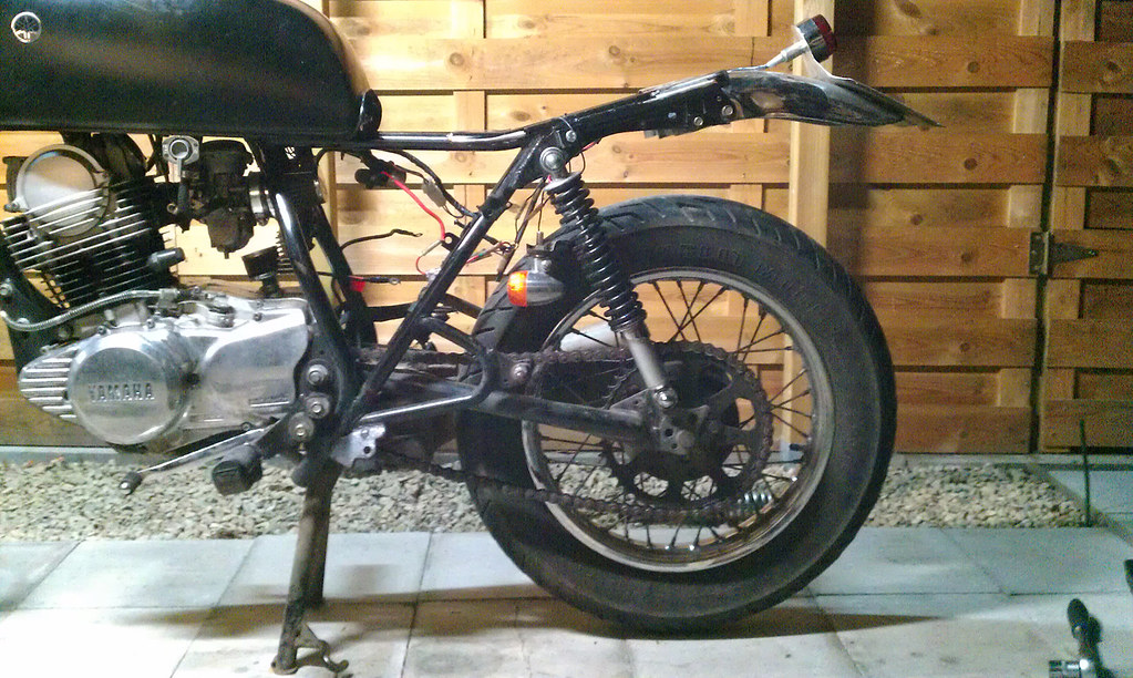
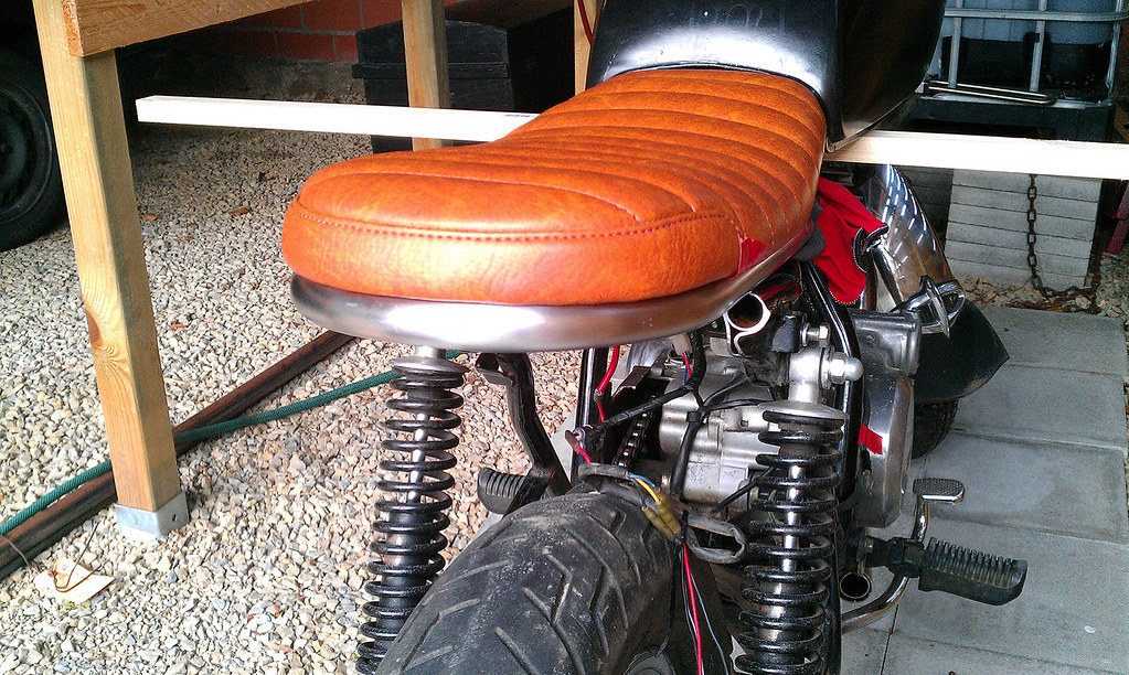
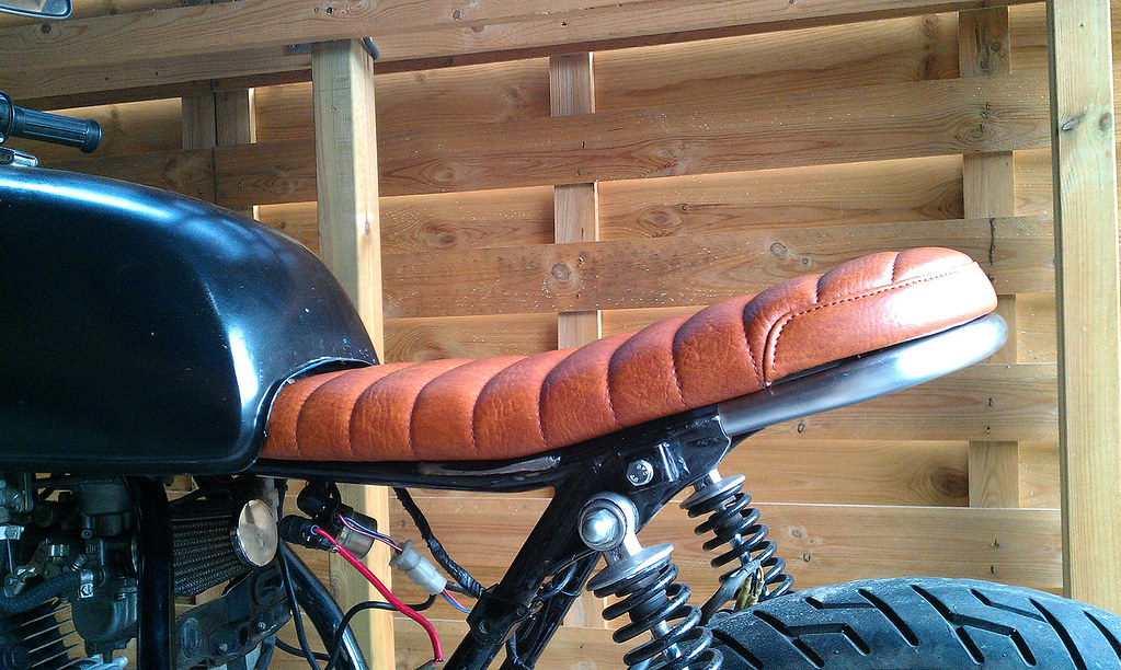
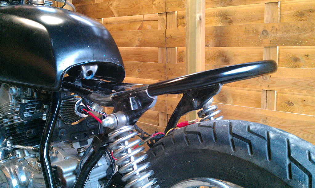
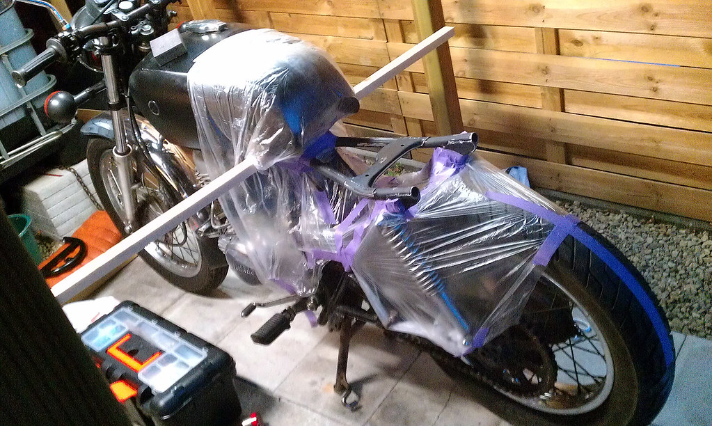
And this is where she sits currently:

11842673413_bc3318433a_b.jpg


11842678813_f280b3f747_b.jpg


11842683113_0c8a5d6eaf_b.jpg


Managed to fix (and break) a lot of things, and snapped a lot of pics in the process, so i figured it was time to give her her own build thread and get some creative feedback from you guys. Say, share, upload whatever you like in this thread. It can only benefit from it.


Next time i get around to it i'll post the pics and progress from the last 2 months.
If it's ok with you guys i'll try to split it into seperate posts for easy viewing.


Thanks for reading!
 
Thanks guys.
I like the direction it's going for now, the rear end/seat really makes it a different bike, but it's still a looong way from finished.

The seat is a custom made for this bike. I made a steel baseplate and dropped it off at a local upholsterer and let him shape the foam and stitch the leather. It's a long story, but it was next on my list, so i'll try to post more details tonight. I'll have to get a better camera though, 'cause it looks a ton better in person, but most of the time i only have my phone within reach. It looks very orange in the pictures, but i would describe it like a vibrant tobacco with a subtle marbled texture.
 
It's been quite the weekend. Had to clean the carburetor 'cause after the first test run the carb was overflowing and was squirting gasoline all over the place. Cleaned the float bowl and float needle and measured the fuel-level, which was normal after cleaning, so no more overflowing carb problems. Still have to revise the petcock though.

So, first thing i had to fix when i got the bike was the subframe. The previous owner removed the brace under the seat with a hacksaw and didn't even took the time to clean it up. Besides the reduced stability it also started to rust. Since i had to fix the rear end, i decided to do it proper and make a rear hoop. With the seat brace out of the frame, the rear would also be able to fit a flat seat instead of the cut up enduro seat the p.o. installed.

11842922503_90408c68bb_b.jpg


i read some blogposts and decided to build the seatpan out of multiplex, since i didn't have the tools to fabricate something else and i figured it would be easier to attach the foam and upholstery. The SR frames have a slight bend upwards, so the multiplex had to be steamed and bent. Didn't have a steambox or anything, so used a pot of boiling water to cook it…

11842632675_f3839cf378_b.jpg


11843410136_07fc20f0c8_b.jpg


…and bent it using the frame…

11842913523_0a986c3d2a_b.jpg


11842621605_eac5dcec9b_b.jpg


11843404446_20c6e6ed4c_b.jpg


…then attached some foam i got from a camping mat…

11842894613_30acbb0f7c_b.jpg


…and brought it to a local upholstery shop. The owner had a look at it and basically told me he didn't want to upholster it 'cause the foam wouldn't hold it for a month, it would be too soft and rip too easily, so the leather would look like crap. The only way he would work on it was if i remade the seatpan out of metal (the multiplex wouldn't hold the curve of the frame) and let him shape the foam (and use a correct type of foam) and upholster it. He basically brought me down to earth and made me realize that taking a shortcut and having to do it all over again is worse than doing it right the first time.


The new seat pan. Cut, bent, sanded and ready to weld some threads on:

11843025424_2c73983e43_b.jpg


11843020684_4f9254783d_b.jpg


11843382006_301b0bc4ac_b.jpg


Weatherproofing it with some satin black:

11843009944_972a490770_b.jpg


11842576145_726ea15057_b.jpg


Semi-finished product:

11842993574_70e0906344_b.jpg


11842564535_eb152ae76b_b.jpg


Ready for upholstering:

11843352766_1f60d681ee_b.jpg


Only thing left to do now was deciding on the saddle height, choosing the leather and searching for some pictures the upholsterer could use to build me the right seat. From the beginning i was inspired by Clutch Customs BMW R75/7, and wanted a similar style for the saddle:
(images from thebikeshed and clutch customs)

Clutch-3.jpg


Clutch-2.jpg


Had to wait quite a long time, but the end result was worth it imho. Again, it's not that orange…
(Still have to make decent pics though)

11843271526_f03af00cde_b.jpg


11843198766_9872d1af1f_b.jpg


11843194966_bf530b6215_b.jpg


Still had to find a way to bend the rear hoop without proper dies, but i'll explain that in the next episode.
 
still tuned in... love the detailed seat process... and that the guy was nice enough to steer you into doing it right instead of giving you a seat that would just fall apart.
 
Re: SR250 Brat/Street Tracker - First Build (aka Little Trouble Kid) - pic heavy

Thanks D4N63R, didn't know i was also following your build. Seems to come along nicely.
Been sick this week, so couldn't do much else than sleep.

Yeah, the upholsterer raised my standards for this build and i'm using the seat as a reference point. He also misquoted the price for the seat and i ended up only paying for the materials and got the hours for free. Nice guy.


So, while i had to wait for the seat i got busy with the batterybox, rear suspension and other small bits.
Decided to fabricate a new tank mount, since the p.o. didn't really took the time to fabricate something decent, and the tank had to be lowered to fit snug with the new seat.

Old bracket on the left, new on the right:

11842556245_8d6914c35e_b.jpg


Also bought some XT stereo shocks to raise the rear and get a nice horizontal stance. There were some copper bushings pressed in the rubbers, so had to cut them away first:

11842547825_1d61534c70_b.jpg


And the new stance, raised 5cm (around 2 inches):

11843336026_80b9458d69_b.jpg


Really loved the way the tank would follow the lines of the frame, and the lifted rear stance, but unfortunately the swing arm would get stuck behind the muffler (had to cut that one eventually) and the springs for the rear brake en brake pedal wouldn't work properly anymore. The center stand would swing all over the place, and the chain would rub the swing arm axle. Only solution was to re-fit the original shocks.


For the batterybox i drew a template in illustrator and (temporarily) glued it to some Aeronaut 1mm Aluminium:

11842955764_3b774f7385_b.jpg


11842814273_76e7e88f23_b.jpg


It consists of 2 pieces that would eventually be JB Welded together and secured by rivets. I was surprised by the final strength of the box.


Also had to fabricate some hollow bolts for the new Daytona turn signals that arrived in the mail. The hollow bolts weren't provided, and ordering would take at least 6 weeks since they had to come from Japan. So i searched for some similar ultra fine threaded M10 bolts (P1.25) and decided to have fun with my drill press:

11842821623_48c64510a4_b.jpg


(Original on the left, drilled and sanded on the right) They fit perfectly.


The upholsterer finished the saddle, but i still had to fabricate a rear hoop. Didn't know anyone with the correct size dies, and it would cost a couple of hundred euros to have one made, so i researched some other ways to bend tubing and stubled upon the oldschool ways: Filling the tube with sand and bending around a wooden die. I actually filled mine with salt, which was easier to come by.

Got to work on cutting and fabricating the wooden die. It had to be as smooth and curved as possible, sturdy and besides the perfect fit have a bit of extra bending room to compensate for the tubing springing back:

11842524045_3ec71f587c_b.jpg


11843313046_18c5c48f0d_b.jpg


After about 1,5 hours of bending (didn't have anything to fixate the die):

11842803713_ce50ef970a_b.jpg


11843300116_941a2e6693_b.jpg


To my own surprise it worked out pretty good.

Measuring on the frame:

11842504405_4643c7c79f_b.jpg


Got my grandfather to help with fabricating and welding brackets for the hoop:

11842924694_d1917a9e45_b.jpg


These aren't the cleanest of welds, but i don't think they are ever coming off.
The small tab will hold the rear fender, the large bar will support the seat and add additional stability to the rear end:

11842495465_73cc02241c_b.jpg


Had to shorten the subframe to make the rear hoop fit with the curve of the saddle:

11842492565_218d9fe966_b.jpg


11842912584_cd597bd11f_b.jpg


11843271526_f03af00cde_b.jpg


Measure, measure, measure, …

11842474195_a83a340ea7_b.jpg


11842754813_279344a2c9_b.jpg


11843256396_eac67dc784_b.jpg


11842745063_1bbb351ef4_b.jpg


It fits!

11842880704_d0c83d8df3_b.jpg


11843243366_a608ca833c_b.jpg


11842871374_662d67eca4_b.jpg


11842727843_3b7178e57b_b.jpg


The empty spaces in the cut up subframe would be filled with some metal-paste, sanded and painted.

The rear hoop had to be welded on, but since the bike wasn't moving, and i didn't know anyone who could weld it on, i decided to bolt in some metal plugs that could be left in when i would let someone weld it in the summer.

Pre-drilled and threaded:

11843231906_ecebceb560_b.jpg


11843227946_1b27208eb3_b.jpg


Painted and ready to bolt through:

11842432085_287f9645bb_b.jpg


11843220296_5339ae4b62_b.jpg


Plug and play:

11842848244_9f6f16dbc2_b.jpg


11842706943_d217a0401a_b.jpg


11842415795_018956aee9_b.jpg


Sanded and taped the rear end:

11842410565_7ccd0880c0_b.jpg


Drilled and cut the rear fender, soldered the rear light, fabricated a brakelight and license plate holder, and bolted everything together.
Ready for the first test-ride:

11843198766_9872d1af1f_b.jpg


11843194966_bf530b6215_b.jpg


Wrapped exhaust and new muffler:

11842683113_0c8a5d6eaf_b.jpg


Battery box in place:

11842678813_f280b3f747_b.jpg


11842673413_bc3318433a_b.jpg


Unfortunately, after 15min into my first ride i pulled over and saw the carb overflowing through the pod filter into the crankcase. I suspect the float was stuck and couldn't get it loose. On top of that, the vacuum operated petcock wouldn't shut off, so had to drain the full tank into a bucket. Next job would be cleaning the carbs, and revising the vacuum operated petcock…

She's starting to deserve her name.
 
Oh, and i have my first question for DTT.

I installed my newer, smaller Daytona turn signals in the rear, which was plug and play.
When i wanted to change the front signals i noticed these had 2 wires, while the replacements only had one (probably grounded through the bolt). I'm guessing i only have to connect the positive wire from the old signals when installing the Daytona's? And leave the ground wire exposed because the signals are grounded through the bolt/housing?

These are the turn signals:

Daytona_TurnSiganls_2.jpg


Daytona_TurnSiganls_1.jpg


(images from Buzzard Toast, another fine build: http://buzzardtoast.blogspot.be)


Do i also have to swap out the original thermal relais for and electric one? Does it make a difference if it's specific for leds?
The turn signals arend leds but have a 23w bulb. The original have a 27w bulb. With only the smaller rear signals and original front signals installed its already blinkin' at half the rate, so i'm guessing they wil stay lit when i install the front signals… ?
 
It looks like the housing is plastic - hence the 2 wires as you suspected; you will need to connect the ground wire to ground. Easy enough to test with any 12V battery and a pair of alligator-clip test wires (i.e., connect positive light wire to battery positive and check the other light wire and light body against battery negative). RE the flasher unit - 23w vs 27w should not make enough difference in load to the conventional flasher; switching to LEDs would as they draw MUCH less wattage.
 
nice work so far! i'm especially impressed with your seat hoop, did you heat that to bend it around your jig? also, what size wall is the tube you used?
 
Thanks guys!

@zap2504: We're probably thinking the same thing, but just to be clear; the daytona housing is aluminium and acts as a ground, the original housing is plastic so it needs the two-wired approach. If i follow the wiring diagram below i just have to connect the turn signals to the brown and green wires and leave the black ones exposed (well, i'll insulate the ends to be safe)? I did the same thing for the rear signals and those worked, only now my relay intervals at half the rate it did before. Am i missing something?

x51d.jpg


Full-size image can be found here: http://img560.imageshack.us/img560/3927/x51d.jpg


@7aliveatlast7: didn't have to heat anything. The jig was made to fit the bend, and hold the pipe in place on one end. Put a cork in one end of the tube, filled it with kitchen salt, tapped it on the ground to compact the salt and closed the other end with a cork too. Didn't have a vice to hold the jig in place, which made it alot harder to bend. If you have some sort of pipe that can hold one end of your tube inside, you can apply force and use the tube as a lever to bend itself. Make sure you try to bend it as far as possible in one motion when you get it going, 'cause it's a lot harder to bend it a little extra when it's just not bent far enough. Had to fixate my hoop on the jig with brackets, so it's a little scuffed up from the brackets and scratched from trying to bend it against a wall and the ground, but it came out quite nice. A lot better and cheaper than i expected.

Had to order the tubing from a metal-working factory because i wanted the same dimensions for the tubing as the factory frame used but couldn't find it anywhere else. If i remember correctly i had to order 6 meters (factory minimum) of DOM 22x2mm steel tubing (diameter x wall thickness). I guess it equates to DOM 7/8"x.079". Also had to buy 6 meters of round bar (20mm dia.) to fabricate the lugs used to fix it to the frame. Since i didn't have a turning lathe i used a drill press and two hand files to get a couple of millimeters off.
Think i will fabricate a side-stand and other stuff with the remaining 5m of tubing :)

Next update will be wednesday i guess. Still waiting for some parts…
 
chiel said:
@zap2504: We're probably thinking the same thing, but just to be clear; the daytona housing is aluminium and acts as a ground, the original housing is plastic so it needs the two-wired approach. If i follow the wiring diagram below i just have to connect the turn signals to the brown and green wires and leave the black ones exposed (well, i'll insulate the ends to be safe)? I did the same thing for the rear signals and those worked, only now my relay intervals at half the rate it did before. Am i missing something?

I don't think you missed anything, but if I were you I'd make up a short negative connecting wire with a bullet connector on one end and a ring connector on the other (to fit the turn signal bolt diameter) rather than assume the bolt is connected to a proper ground (the whole headlight frame might be isolated from the frame or not have a good ground path). This way you can retain the OEM wiring harness but provide a proper ground for the turn signal.
RE current turn signal flashing rate - it may be that the flasher unit is so delicately balanced that a minimal change in load (i.e., 27 to 23W) is enough to change the flash rate. I'd try it with two 23w bulbs. If it flashes way too low, then you will need to replace the OEM flasher with an electronic unit that is not dependent on bulb load (like one for LED lights).
 
Thanks zap2504, that's a smart solution, didn't think about that one. I recycled a spring washer and wire with bullet connector from the old signals and soldered them together. I'll try to hook it up tonight and see if the ground wire works with the existing wiring harness. Seems to be a straightforward swap.

Lost a lot of time last night trying to insulate my megaton exhaust. Seems the baffle is stuck and finally had to give up. Will try again tonight.


Soldered ground connectors:
 

Attachments

  • IMAG1012.jpg
    IMAG1012.jpg
    1.8 MB · Views: 652
  • IMAG1008.jpg
    IMAG1008.jpg
    1.8 MB · Views: 641
Thanks Yamaki. It's still a long way from finished, but that's all part of the fun I guess. Apparently I was following you Serotonin build when I first got my bike. How do you like your SR?
 
Re: SR250 Brat/Street Tracker - First Build (aka Little Trouble Kid) Elec. probs

zap2504 and all you DTT electrical wizards, i need your help.

Before replacing the old front flashers (double wire) with the new Daytona signals (single wire) everything worked fine. I already replaced the rear and connected the single wire with the leads (green and chocolate brown in the schematics), left the ground wire in the harness unconnected 'cause the flasher grounds through the body. Now, for the front flashers i followed your advice zap2504 and fabricated a ground wire, which connects the body (through the bolt), with the black (ground) wires that used to ground the double wire flashers. So essentially, the single wire signals turned into double wire switches and could connect to the stock wiring harness without being afraid of a bad/missing ground. Everything connects exactly like the diagram suggests. Only thing that changed using the newer signals is the relay not switching anymore. While using only front flashers it was blinking at half the rate, and using all daytona signals keeps the left or right signals lit constantly. I guess these signals don't have a high enough load and could benefit from a LED flasher?


The problem i'm having now is regarding the brake light…
While connecting the signals to the spaghetti of cables inside the stock headlight i first connected the Left Front signal. When disconnecting the Right Front signal the ground (–) cable from the right flasher was still connected, while the lead (+) cable was disconnected, slipped from my fingers and touched the housing of the Horn, which went off. Disconnected the brown from the horn housing, disconnected the black from the old flasher and hooked up the new Right turn signal.

Now, when all lights are off (idiot light from neutral is on) and i engage the front or rear brake, the brake light switches on, alongside the front parking (auxiliary) light and the Meter light (dash light). These 2 lights are also switching on and off while using one of the brakes, which makes my dash light flash, and my front parking light. When i switch the parking light on through the handlebar switch, the rear brake light stays lit. Same thing with the headlight switched on, the brake light stays lit. What could be the problem here?

When i look at the schematic, i can see they share some of the same parts from the wiring harness, so i can understand this problem is related with some of these parts, but i can't see any solution. I double checked the wiring inside the head light. The turn signals are hooked up correctly, according to the schematic, and i can't find any loose or false-grounding wires, as far as i checked…

Could it have anything to do with the flasher relay not flashing anymore? While i was double checking brake light problem and the front flashers i replaced them with the previous flashers. They were flashing again, but the brake light problem persisted. So i didn't short the relay.

Could it have anything to do with the disconnected lead wire from the right front signal touched the horn housing and made the horn go off? The horn still works though. Did i fry anything?

Is there something i can check, or measure with a multimeter?

I still have to connect the carburetor and change the oil, so for now i can't check if the bike fires up.

It has to be something simple, but for the life of me i can't figure it out…


Thanks in advance.

Some schematics for my bike: (first one uses the same wiring for the front signals, auxiliary light and dash lights)
 

Attachments

  • 2001 SR250 - Original Wiring Diagram.png
    2001 SR250 - Original Wiring Diagram.png
    59.1 KB · Views: 9,375
  • 2001 SR250 - Original Wiring Diagram 2.png
    2001 SR250 - Original Wiring Diagram 2.png
    15.9 KB · Views: 1,008
  • Yamaha SR250_Esquema Electrico Blanco y Negro_03.jpg
    Yamaha SR250_Esquema Electrico Blanco y Negro_03.jpg
    215 KB · Views: 6,193
  • Yamaha SR250_Esquema Electrico '96-3TH-MS1 (por Picatuelo 2010-05-03).gif
    Yamaha SR250_Esquema Electrico '96-3TH-MS1 (por Picatuelo 2010-05-03).gif
    283.2 KB · Views: 1,413
Re: SR250 Brat/Street Tracker - First Build (aka Little Trouble Kid) Elec. probs

chiel said:
Before replacing the old front flashers (double wire) with the new Daytona signals (single wire) everything worked fine. I already replaced the rear and connected the single wire with the leads (green and chocolate brown in the schematics), left the ground wire in the harness unconnected 'cause the flasher grounds through the body. Now, for the front flashers i followed your advice zap2504 and fabricated a ground wire, which connects the body (through the bolt), with the black (ground) wires that used to ground the double wire flashers. So essentially, the single wire signals turned into double wire switches and could connect to the stock wiring harness without being afraid of a bad/missing ground. Everything connects exactly like the diagram suggests. Only thing that changed using the newer signals is the relay not switching anymore. While using only front flashers it was blinking at half the rate, and using all daytona signals keeps the left or right signals lit constantly. I guess these signals don't have a high enough load and could benefit from a LED flasher?
That would be my guess too; not enough load for the OEM flasher to flash.
The problem i'm having now is regarding the brake light…
While connecting the signals to the spaghetti of cables inside the stock headlight i first connected the Left Front signal. When disconnecting the Right Front signal the ground (–) cable from the right flasher was still connected, while the lead (+) cable was disconnected, slipped from my fingers and touched the housing of the Horn, which went off. Disconnected the brown from the horn housing, disconnected the black from the old flasher and hooked up the new Right turn signal.

Now, when all lights are off (idiot light from neutral is on) and i engage the front or rear brake, the brake light switches on, alongside the front parking (auxiliary) light and the Meter light (dash light). These 2 lights are also switching on and off while using one of the brakes, which makes my dash light flash, and my front parking light. When i switch the parking light on through the handlebar switch, the rear brake light stays lit. Same thing with the headlight switched on, the brake light stays lit. What could be the problem here?

When i look at the schematic, i can see they share some of the same parts from the wiring harness, so i can understand this problem is related with some of these parts, but i can't see any solution. I double checked the wiring inside the head light. The turn signals are hooked up correctly, according to the schematic, and i can't find any loose or false-grounding wires, as far as i checked…

Could it have anything to do with the flasher relay not flashing anymore? While i was double checking brake light problem and the front flashers i replaced them with the previous flashers. They were flashing again, but the brake light problem persisted. So i didn't short the relay.

Could it have anything to do with the disconnected lead wire from the right front signal touched the horn housing and made the horn go off? The horn still works though. Did i fry anything?

Is there something i can check, or measure with a multimeter?

Touching the horn body with the black wire just simulated what you do when you press the horn button - the button completes the circuit from the horn body to ground. No damage.

Also - nothing to do with the flasher unit (but the flasher still needs to be replaced with an electronic unit).

I'm guessing that you have one or more wires mis-plugged within the headlight body or wiring harness where you have been recently working that is activating the aux/meter lights with the brake handle. Double check all bullet connections (with a good flashlight) to see that all connectors have the same color wires together (black is ground, brown is +12VDC from the ignition switch, etc.) you should not have any connection where there is more than 1 color of wire (nor any connection where there is a solid color connected to a stripe). Look in the areas you have just been working and you should see it.

BTW - I'd also fab-up some ground wires for the rear turn signals just to re-use the OEM ground bullet plugs and ensure you have a good ground to the signals.
 
Thanks iGreek. First thing on the list now is to get her running again.

@zap2504: Thanks for the solid advice. Will try to check everything after work tonight. Hopefully i missed something and it's an easy fix.
 
So, the wiring… I was convinced it would be something easy, like a brown wire that got mixed up with a chocolate wire, or blue with purple and it would only take 5 minutes to fix my problem. Well, after 3 hours in the freezing cold and literally checking every wire and plug a dozen times … nothing changed :-\ Every connection works out with my schematic. I even suspected the new front signals, so i disconnected them. Still the same problem. I started to think my homemade ground wires for the signals were bridging a circuit through the headlamp bracket, so disconnected them entirely, nothing changed. Well, i should be happy, 'cause this means the turn signals will work once i connect the elec. relay, if i can sort this thing out. I even started to doubt the signal-relay wiring, so disconnected that one, nothing. So if all my connections inside the headlamp are correct, there are only a few more possibilities. But i can't seem to figure out which ones.

I also tried to disconnect the aux light, but the dash still flashed when i applied the brakes. I reconnected the aux light and disconnected the dash light, applied the brakes, and the front aux light still flashed. So if none of these two really matter, could it be inside the front brake switch? Rear brake switch? Is there some wire inside the harness that's exposed and touching the frame or another wire?

I also found a black wire running from the right hand side controls to the front fork brace under the headlight, connected to a bolt that's also holding the horn bracket in place. So i eventually started questioning the switches, and thinking something happened inside when the lead wire from the right hand signal touched the horn body and it went off.

At this point i'm losing hope. What would be the best thing to do? What's the next thing i can check? Is it possible to decipher the problem from the wiring diagram alone? Is there something i should/can measure with a multimeter?

It can't be that hard to find, can it? It's only 2 circuits that are bridged through 'something' that i'm missing.
Could it all be solved if i connect the new flasher relay and start the bike? Or wouldn't it change a thing (i'm thinking about the ECU or something like that)?


Oh, and for the electronic flasher relay i chose this one: http://motogadget.com/en/electrics/digital-flasher-relay-m-flash/m-flash-blinkrelais.html
It's the size of a fingernail, electronic, almost load independent (min 1W), works with all flashers (LED and bulb up to 100W) and only has two wires so i guess it would be easy to substitute my oem relay (2 pin B & L). I'm curious to see if it will work… Only thing i'm not sure about is the fuse. The site says the relay can handle 7A before it fries, the manual suggests a safety fuse of max 10A (http://motogadget.com/media/downloads/manual/mflash_manual_en.pdf) and my bike's main fuse is 20A. Should i connect a second smaller fuse between the brown 49/B (+) wire and the relay, or can i just swap the oem relay without adjusting my wiring?

Sorry for the long (picture-less) post.
 
Back
Top Bottom