CB-R 700SC My crazy idea to put a CBR900RR front end swap on my NHS

WaltNpt

New Member
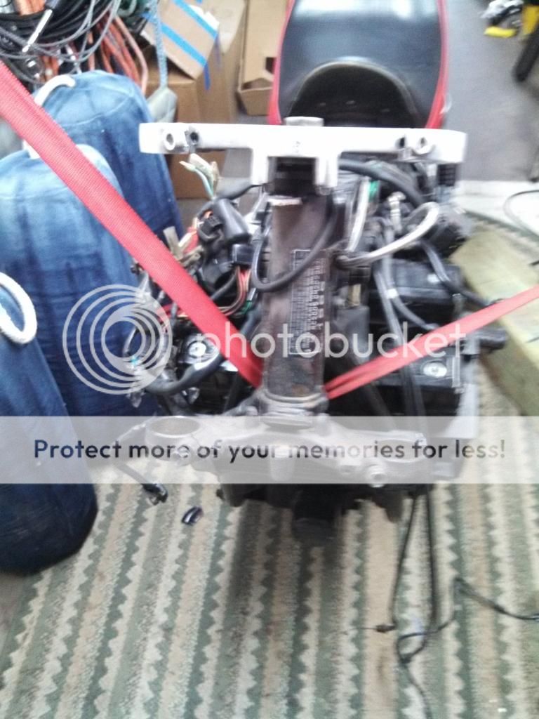
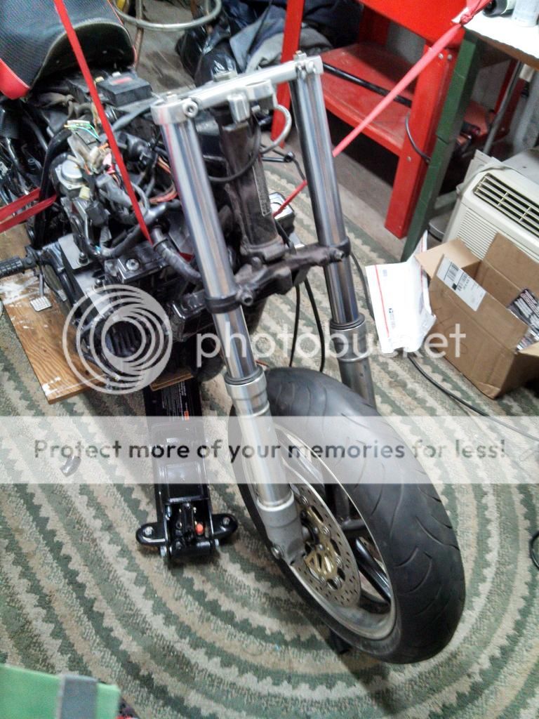
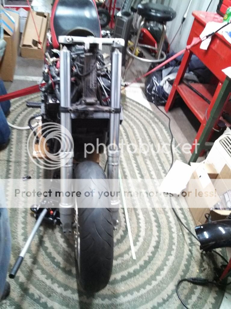
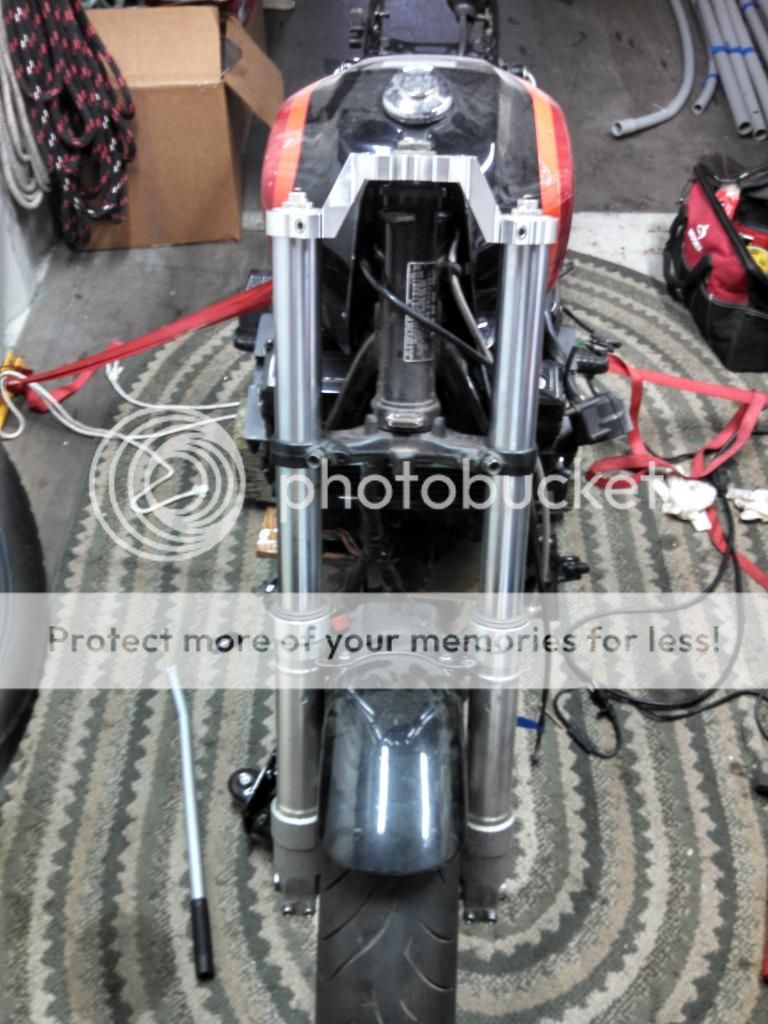
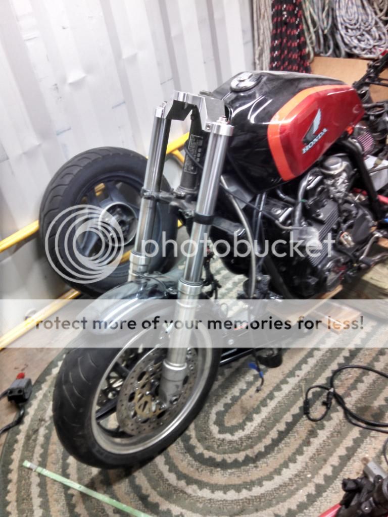
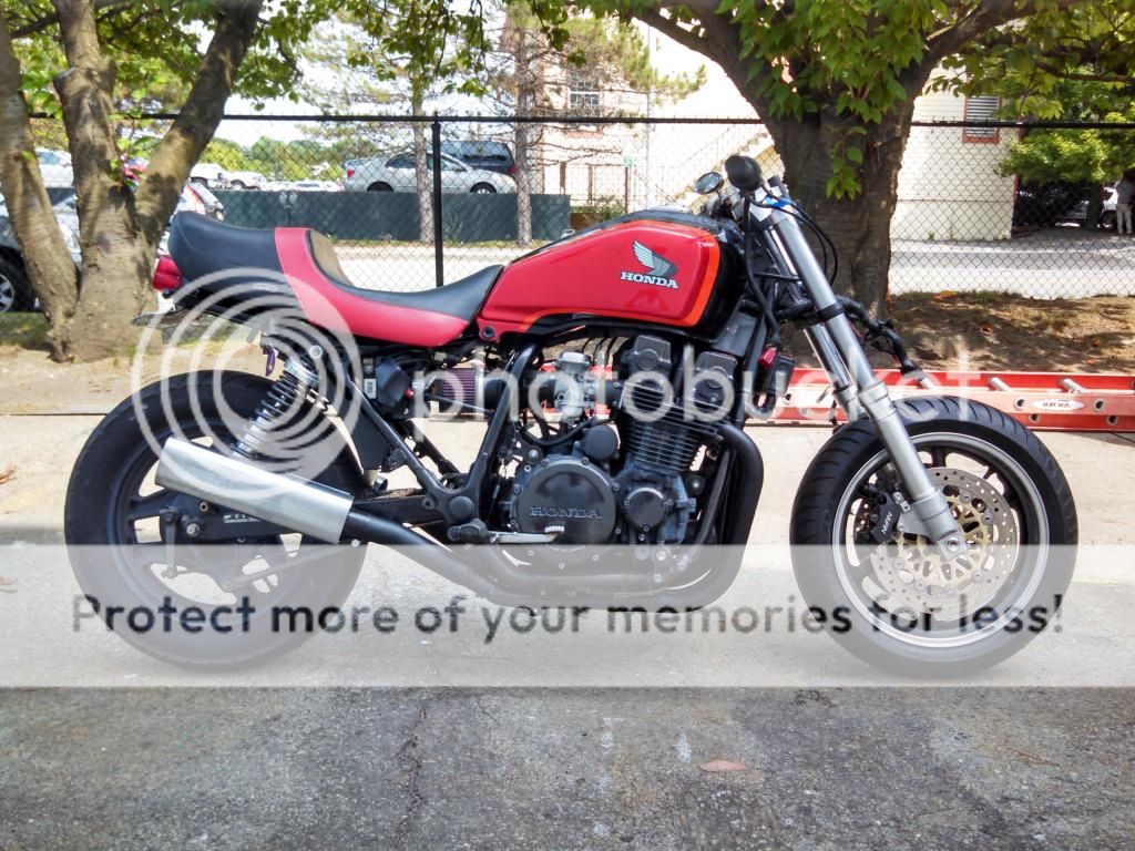
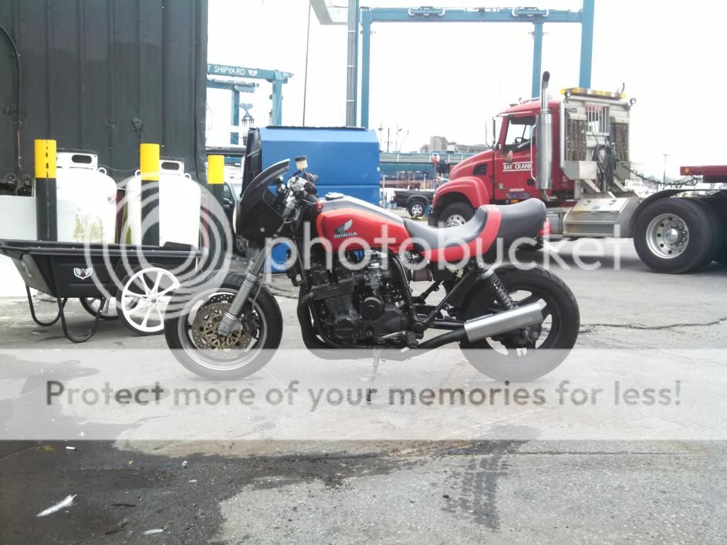
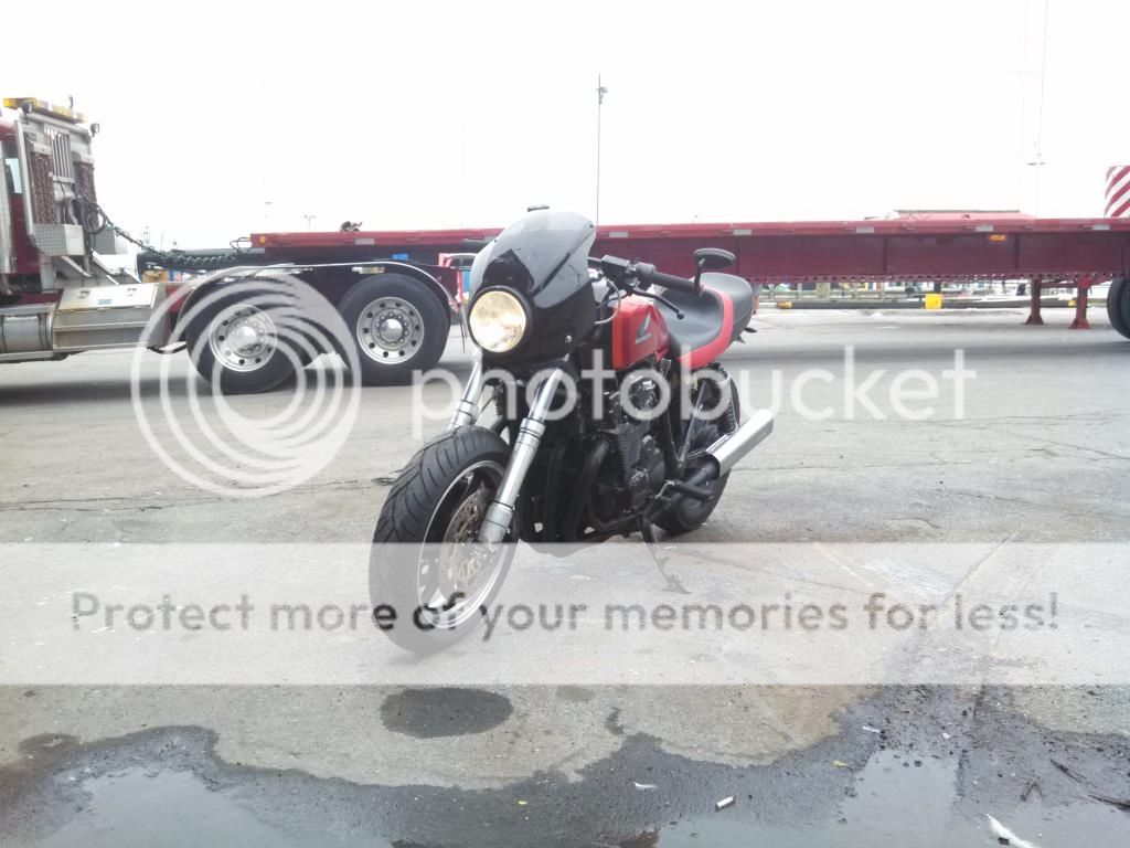
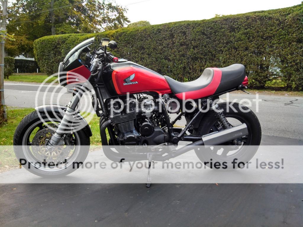
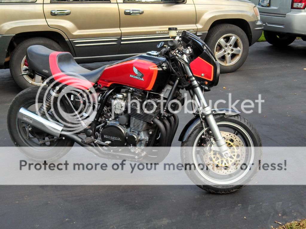
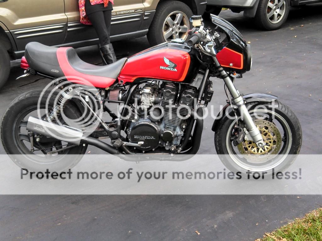
I have been contemplating this project for over 4 years, and after seeing some of the front end mods lately I decided to pull the trigger last fall. It started with the purchase of a 1996 CBR 900RR front clip for $200 on craigslist, and from there has taken me almost 9 months to get to the point I am at now. There has been a lot of planning, fabricating and plain old frustration but it is almost done and I would love to see what you all think.

List of items:
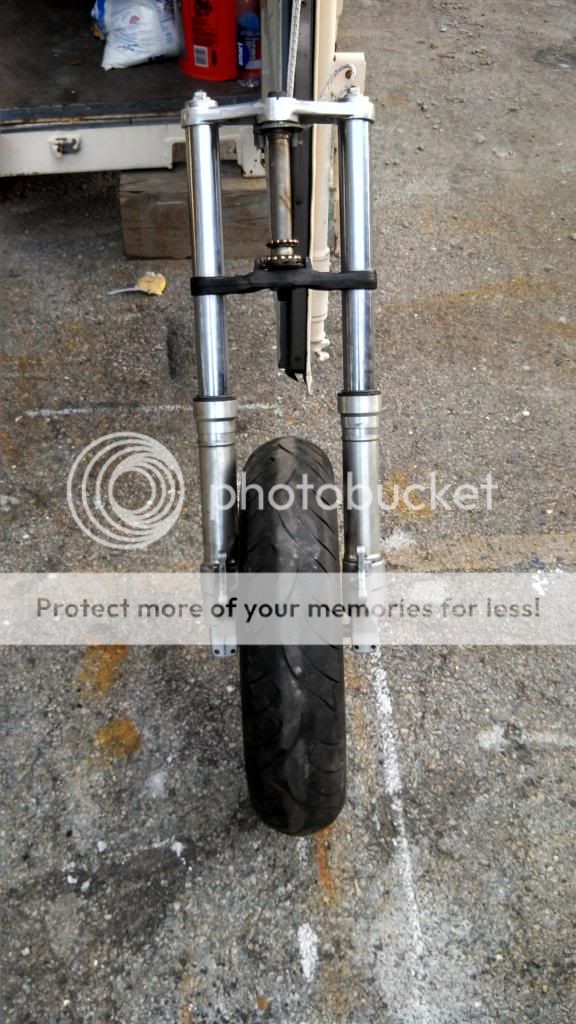
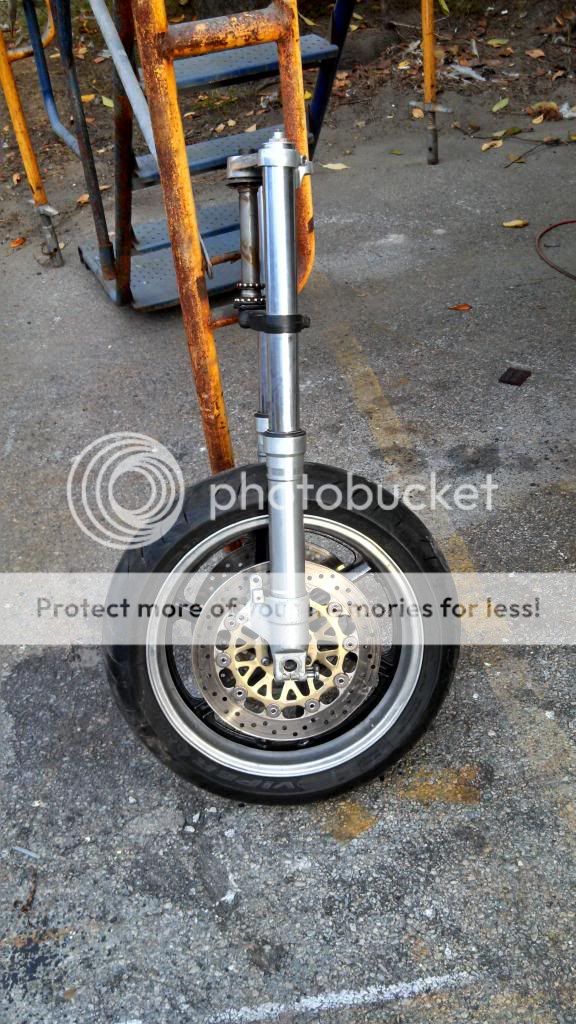
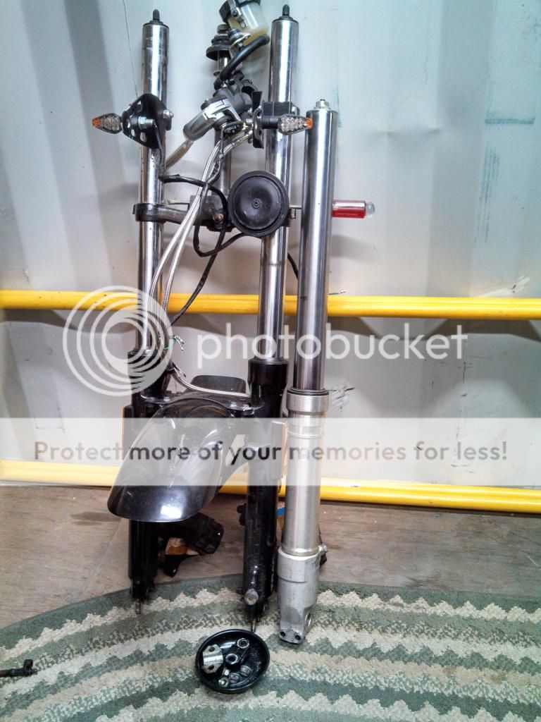
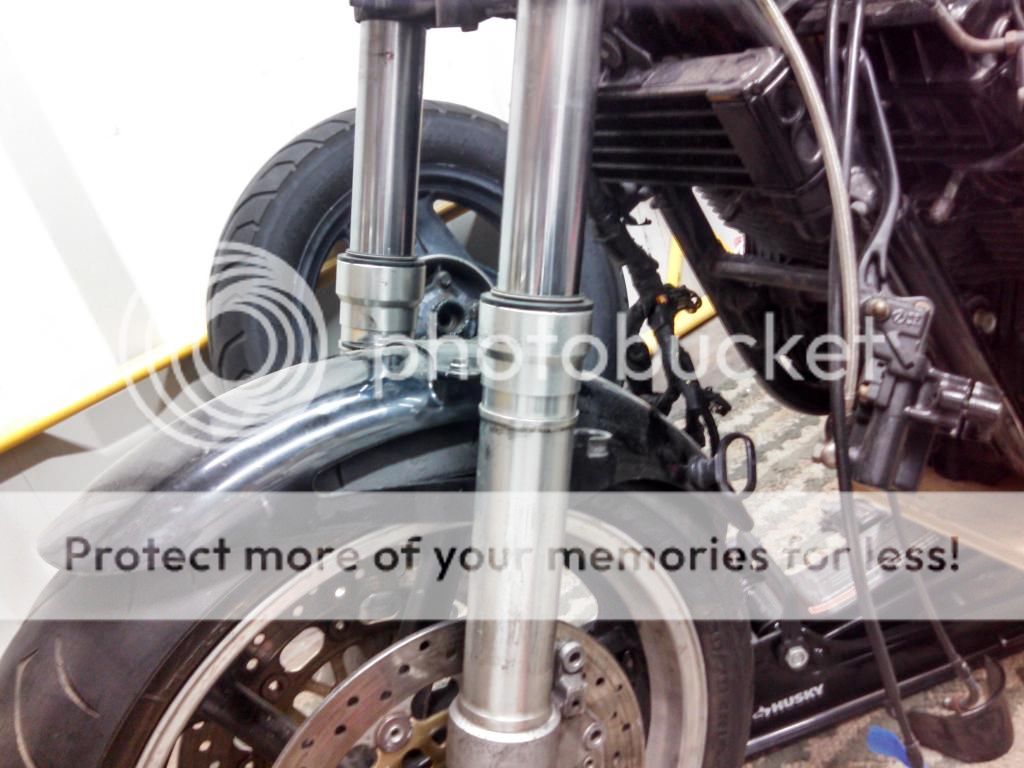
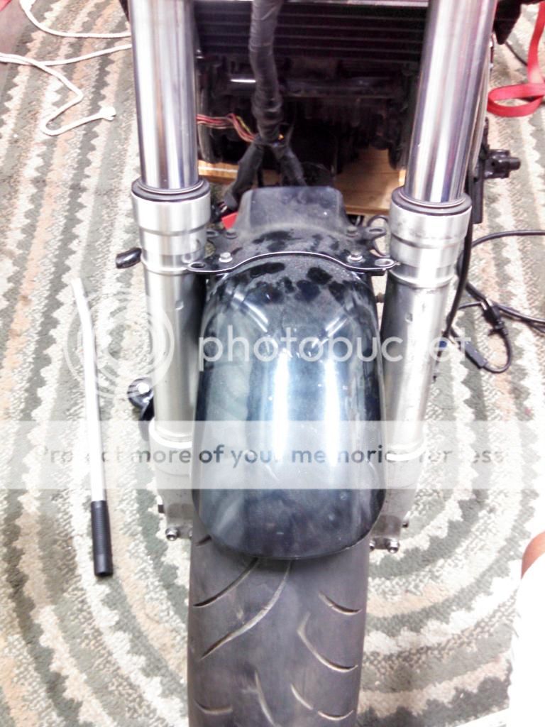
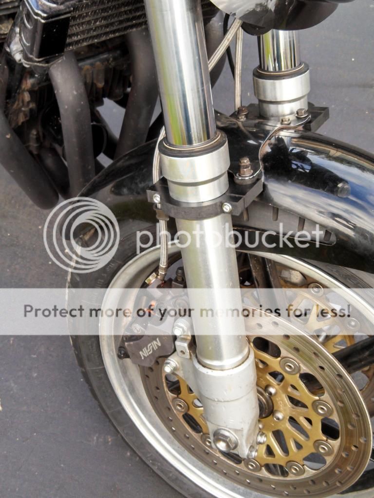
1996 Honda CBR900RR front clip (forks, triples, wheel and brakes)
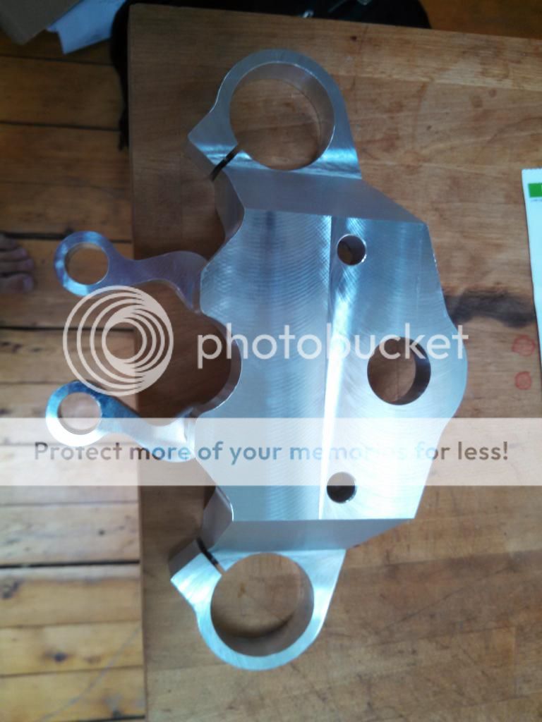
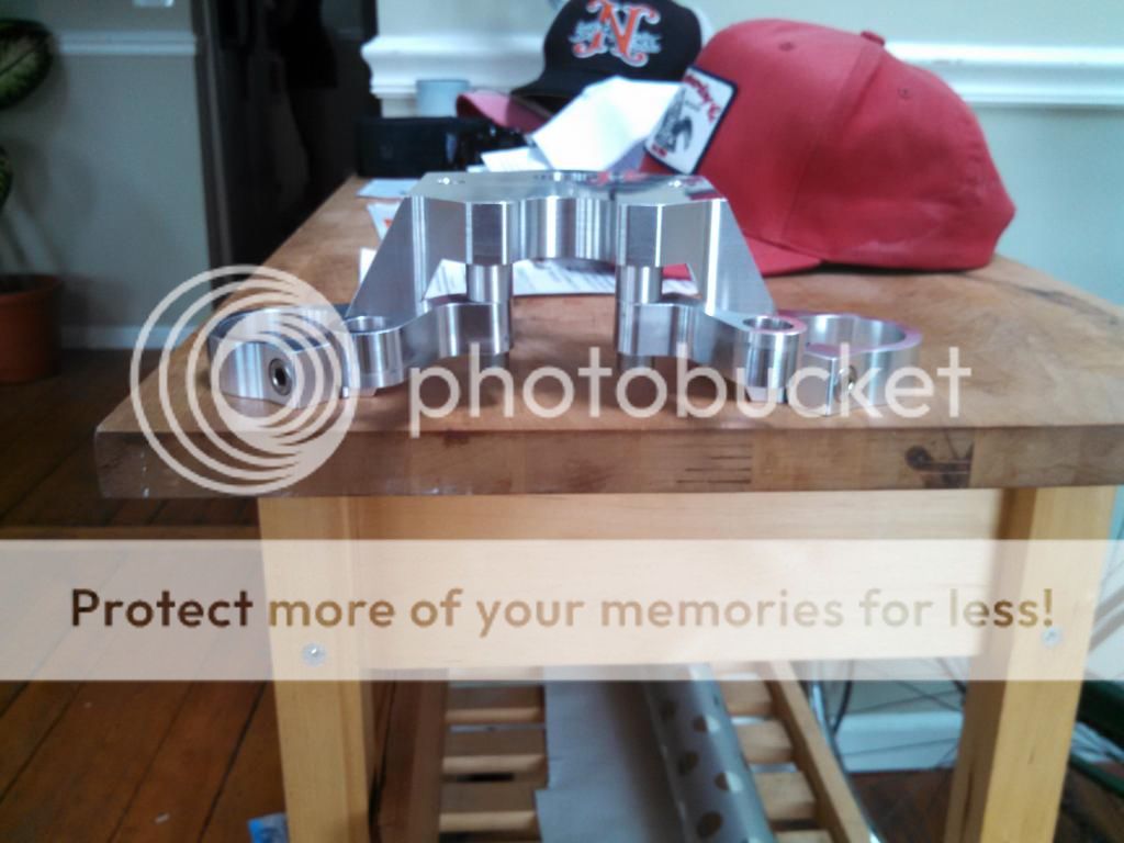
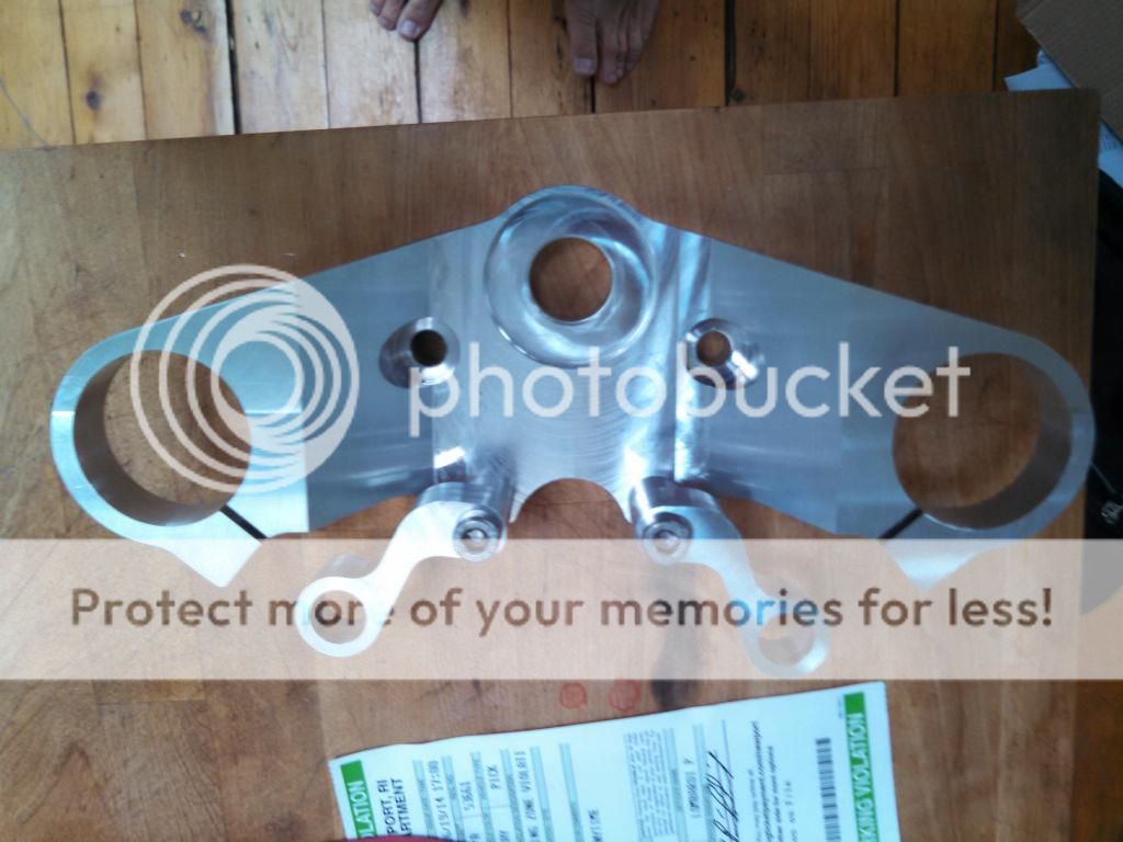
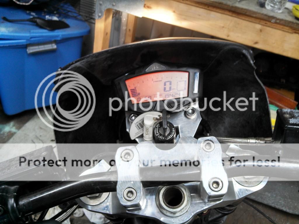
Custom machined Billet Aluminum 50mm drop down upper triple http://www.billetbikebits.com/shop/
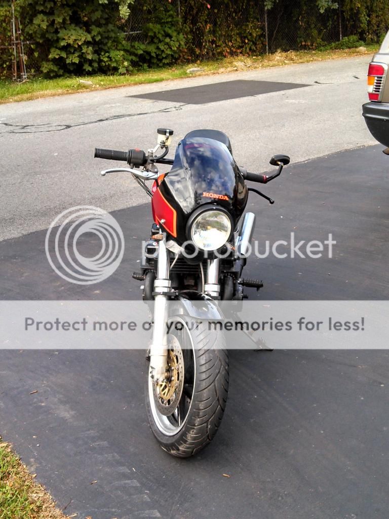
2010 Honda CBR600RR 17mm radial master cylinder
Custom Galfer stainless lines
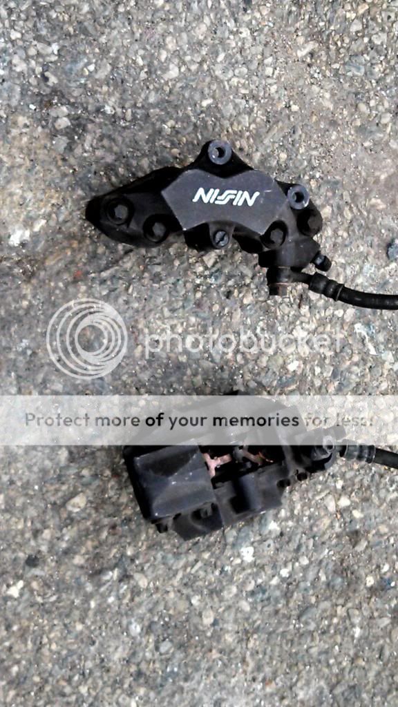
EBC Sintered brake pads
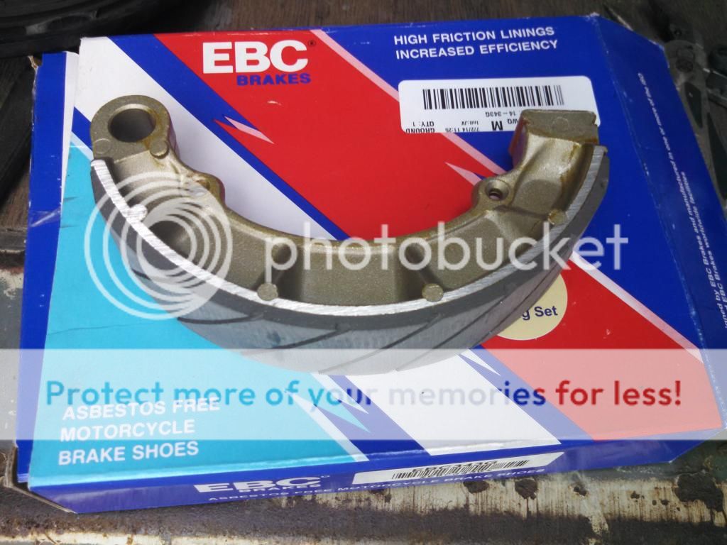
EBC grooved rear brake shoes
Avon Azaro radial tires- Front 130/70-16 Rear 150/80-16 (not installed yet)
All Balls front and rear wheel bearings
Koso DB-03R Gauge
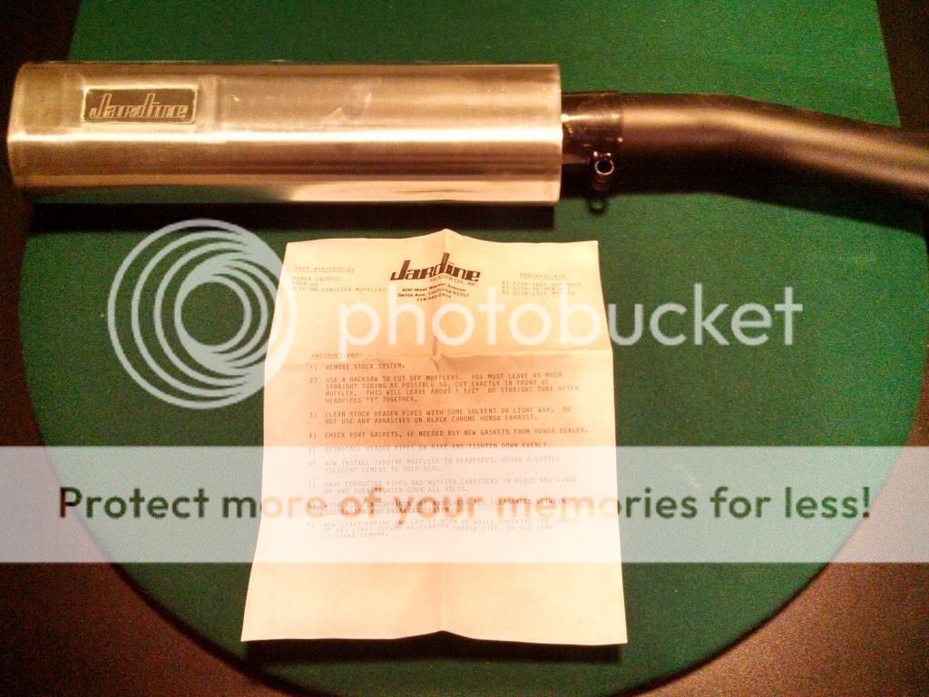
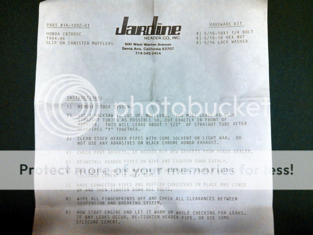
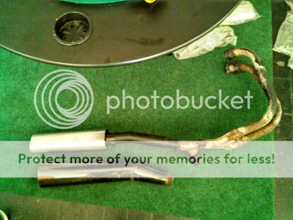
CB700SC Jardine Slip-ons (NOS from 1987 on Ebay)
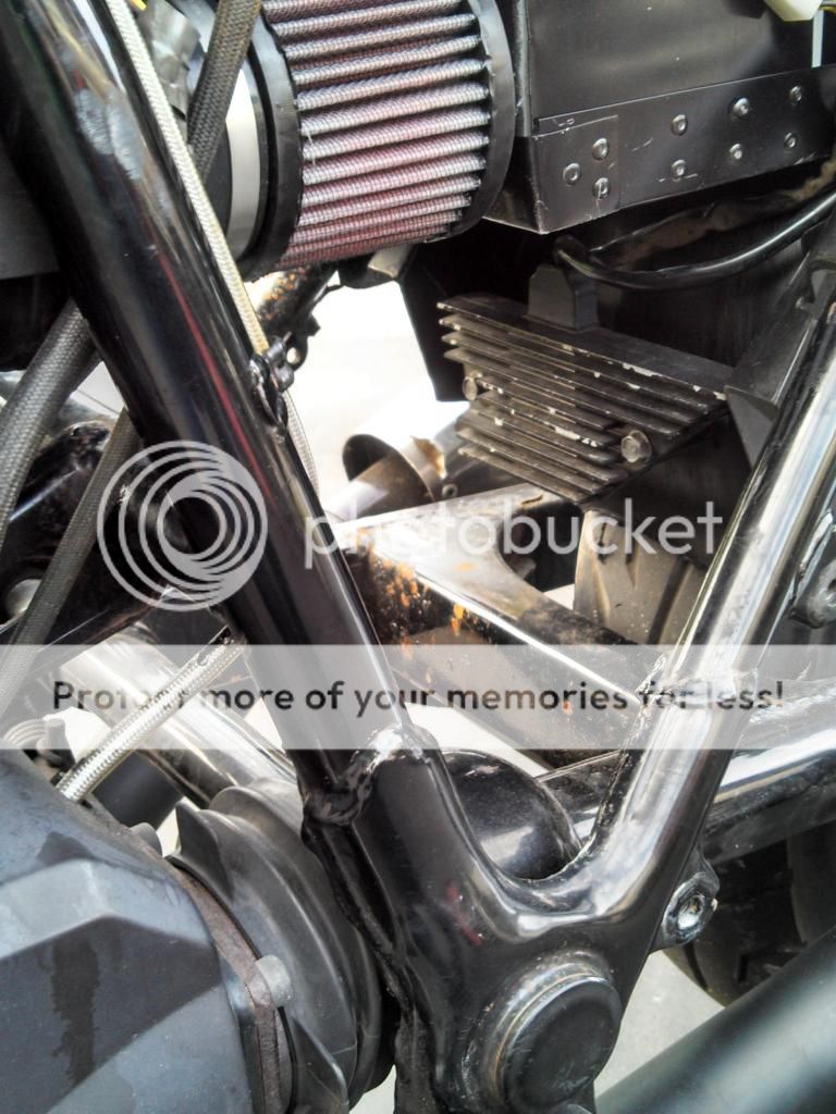
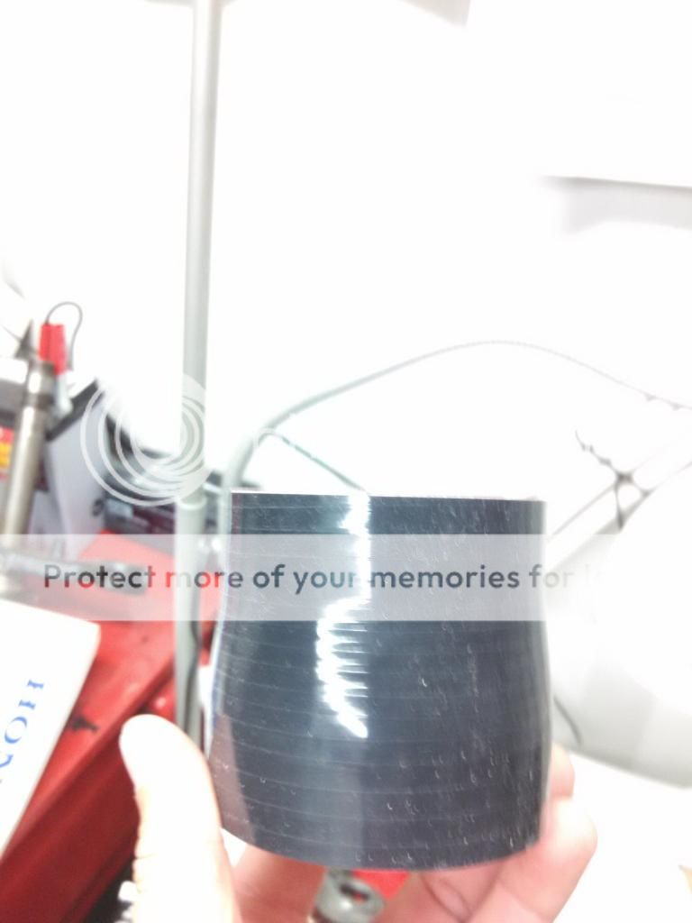
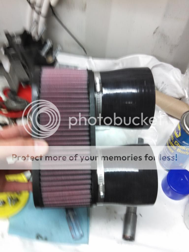
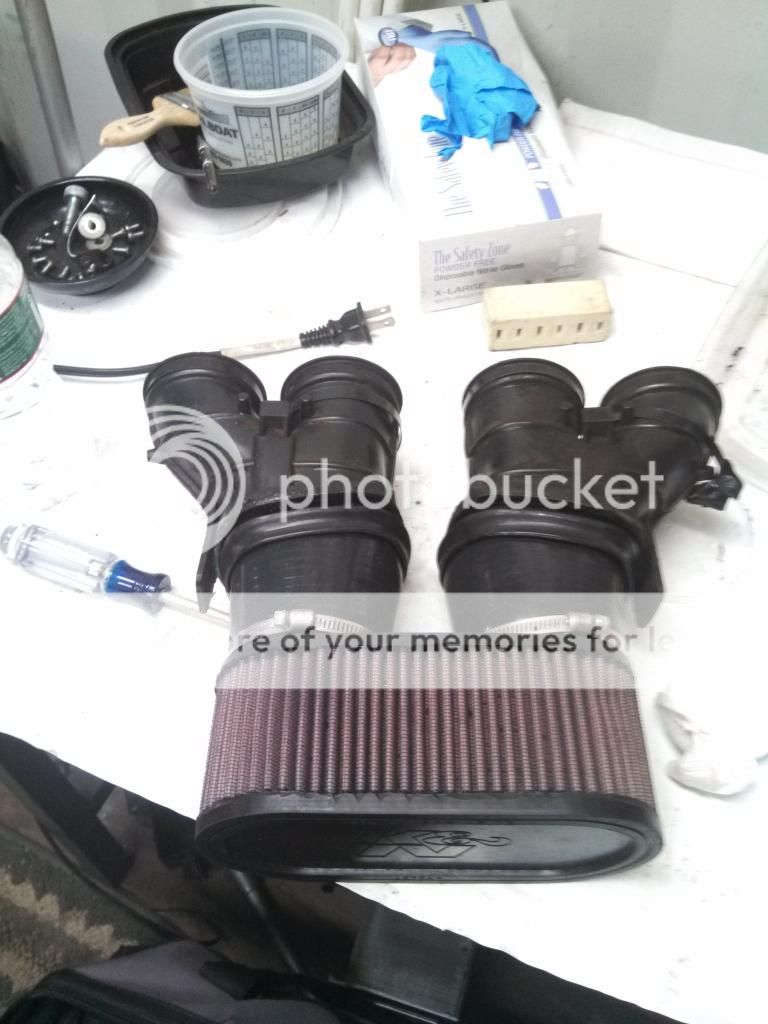
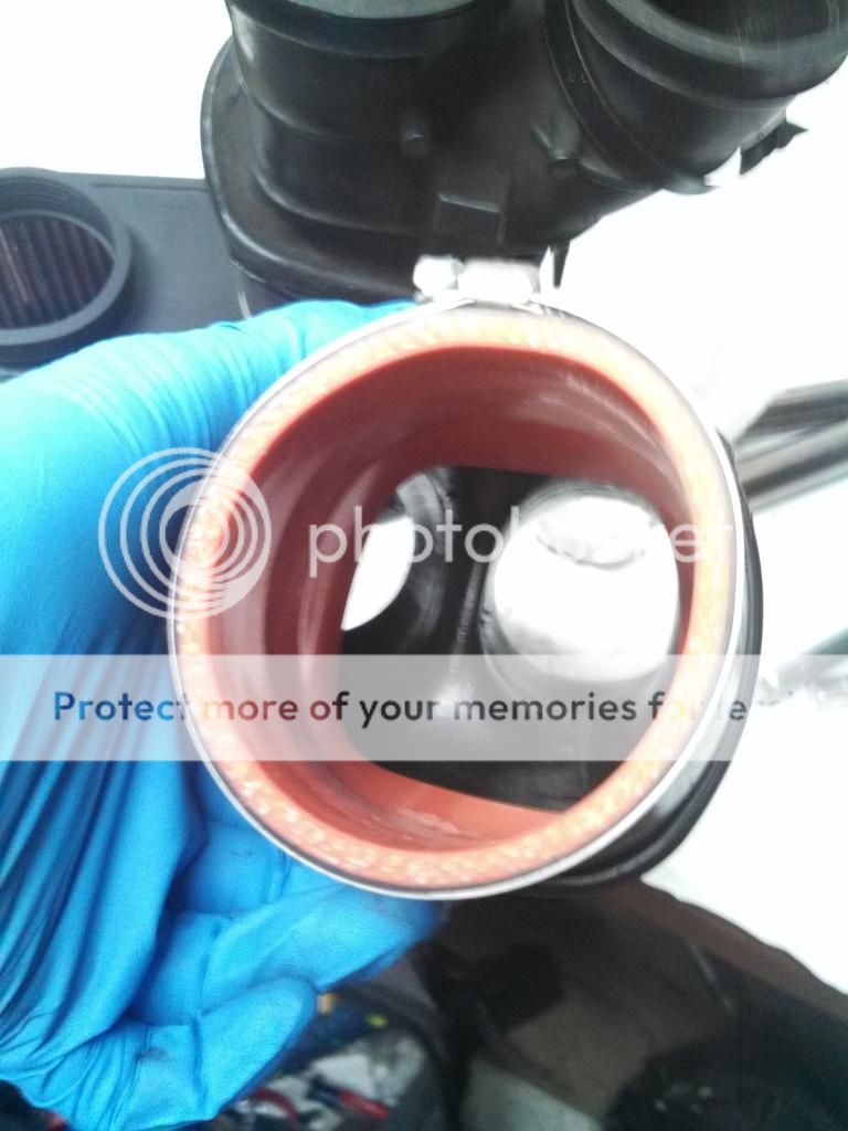
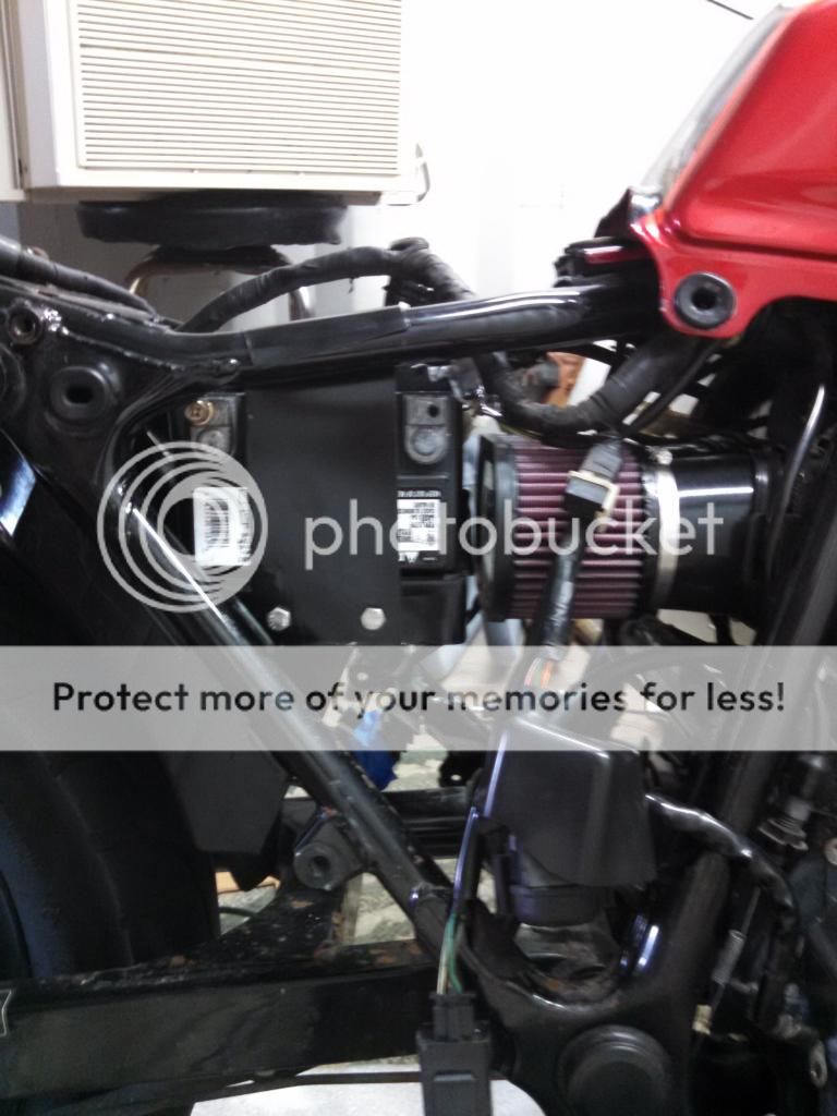
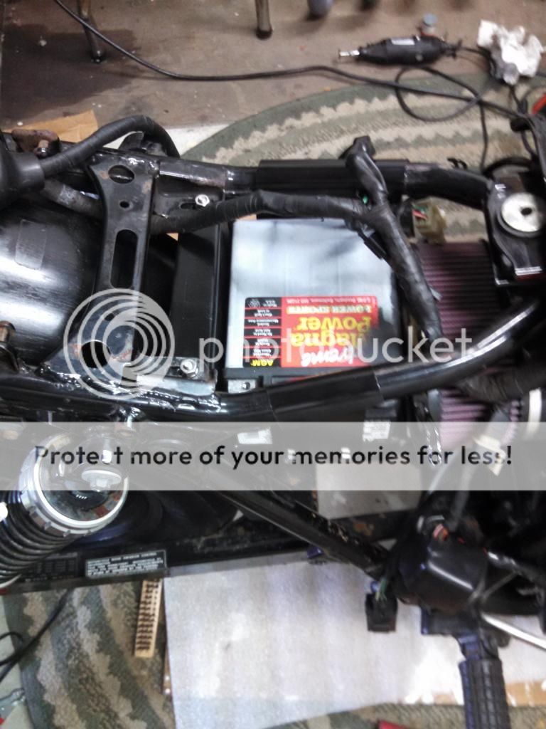
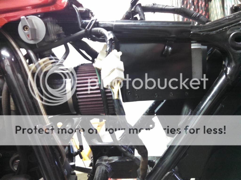
Universal KN filter and silicone hose adapters
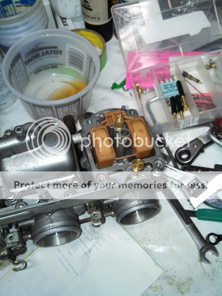
Factory Pro Stage 3 jet kit
New Spark plugs and NGK points
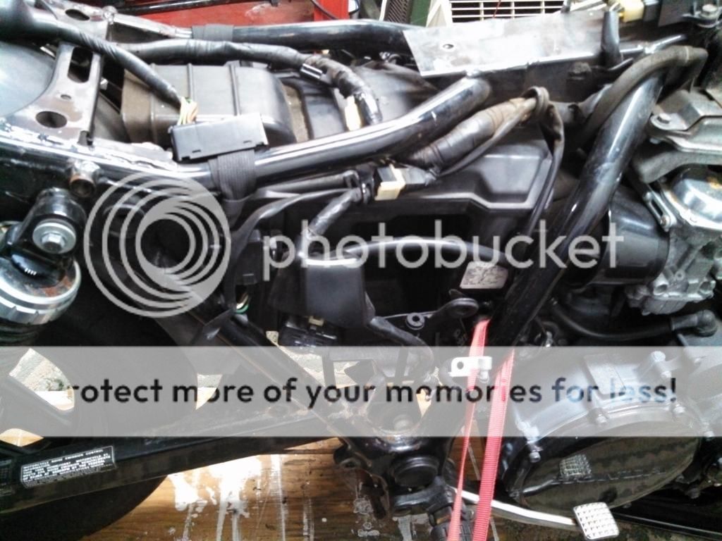
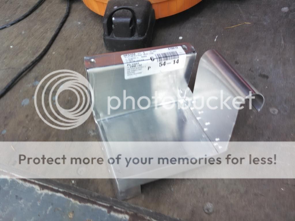
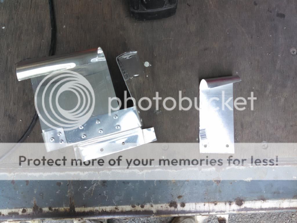
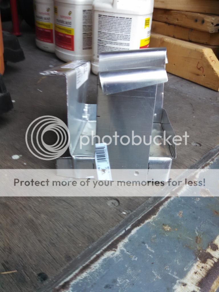
Custom battery box and lengthened negative battery cable
Coming Soon
Sparck Moto harness (ordered and hopefully on bike this spring) sparckmoto.com
Works shocks
Tarrozzi Rear Sets
Paint work
17" wheels with rear disc brake conversion
***there may be some other things I have forgotten, but I am sure you guys will ask, haha***

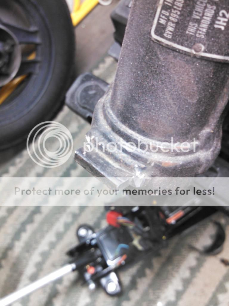
I have a whole bunch of pictures from various projects during the build and will start posting them slowly with explanations along the way.

IMG_20141015_162843_555_zps1897a1fd.jpg
 
The fork lengths are noticeably different almost 5 inches. That is why the custom drop down triple is necessary.
IMG_20140227_175047_654_zps8c69a863.jpg


The CBR shares the exact same stem diameter and bearings as the NHS, however it does not have the same length stem. In order to get the CBR front end to go on you have got to press the NHS stem out of the lower triple and press it back into the CBR lower. It is a bit of pain to get them separated from each other though since both stems are welded to the triples. I have a buddy who is a machinist and does a lot of work on the boat I run, so I gave it to him and he ground the welds, pressed out the stems, re-pressed the NHS into the CBR triple and welded for me. He are some pics of me mocking up the front end after that was done. You will also notice that I had to cut the factory steering rack lock off and the steering stops at the bottom are much farther forward on the CBR. To cure this, later on I simply cut the tab on the frame with a dremmel to provide the necessary distance from lock-to-lock
IMG_20140423_134258_677_zps9579576d.jpg

IMG_20140423_170435_580_zpsa3dc6bfa.jpg

IMG_20140701_144301_981_zpsf6d9b559.jpg


In this pic the forks are dropped 50mm down from the upper triple, this is where I decided I wanted the front end. I dont feel like going through all the math right now but at that point I concluded I would get the rake I was looking for without a large sacrifice in ride height. I only lost about 1.5 inches if I remember correctly. I will try and get the math together at some point just to show all of you.
IMG_20140423_171303_273_zpse2206d73.jpg

IMG_20140423_171029_288_zps595b0d85.jpg
 
The triple was made by Roy of Billet Bike Bits in England. http://www.billetbikebits.com/shop/
He was the most experienced I could find and by far the cheapest! (Even with shipping)
He also provided me with 1 inch risers which are really beefy and fit great.
IMG_20140626_173425_939_zpsa97b5ac8.jpg

IMG_20140626_173443_643_zpsc3f7ffa6.jpg

From below
IMG_20140626_173454_079_zps43c7decf.jpg


All mounted up and the fit is perfect. No wiggle, no binding and no friction, it turns like the factory. Also the stock NHS fender still fits the CBR tire so I am able to use the stock fender.
IMG_20140701_153336_322_zps70d46712.jpg

IMG_20140701_153355_710_zpscb141404.jpg

IMG_20140701_153436_582_zpsd6a94b76.jpg

IMG_20140701_153447_783_zps4666a26d.jpg
 
Using RB racing rake calculator (https://www.rbracing-rsr.com/advchoppercalc.html) these are the stock numbers and then the numbers I have now
Stock setup
Wheelbase= 58.4 inch
Front tire diameter=23.79 (110/9-16)
Rear tire diameter=25.21 (130/90-16)
Rake=30 degrees
Triple clamp offset=1.8 inch
beginning fork length= 34inch
triple rake=0

Results of calculator
Fork angle= 30
Trail=4.8
Rear axle centerline to centerline top of steering neck= 49inch
Wheelbase: Rear axle centerline to front axle centerline=58.4inch
Top of steering neck centerline to ground=40.44inch


CBR front end
Wheelbase= 58.4 inch
Front tire diameter=23.16 (130/70-16) The 130/70 tire is smaller in diameter
Rear tire diameter=25.21 (130/90-16)
Rake= 30 degrees
Triple clamp offset= 1.37 inch (I had to used the CBR offset of 1.37inch when I had my new triple made)
beginning fork length= 30.75 inch (this is including the 2 inch drop from the upper triple, stock is about 28.75)
triple rake=0

By the way when you substitute the offset and the tire the STOCK numbers will be different in the calculator but your NEW GEOMETRY numbers will be right.
Results of calculator
Rake=27.16 degrees
Trail=4.4 inch
Rear axle centerline to centerline top of steering neck= 49.44 inch
Wheelbase: Rear axle centerline to front axle centerline=56.8 inch
Top of steering neck centerline to ground=38.31 inch

So to sum up, a rake change of almost 3 degrees, a trail of .4 inch and a wheelbase change of 1.6 inch. That pretty much means the bike has a rake and trail almost exactly the same as the much nimbler Honda Hawk GT, although with a slightly longer wheelbase.
 
I made the brackets for the front fender out of a block of ABS plastic from McMaster Carr. The dimensions were 6x6x1/2. The CBR front forks have a
2-1/8 inch diameter x 1/2 inch slot where the stock CBR fender mounted.

Used drill press and hole saw to cut wholes. The ABS melts real easy so it was a bitch, haha
IMG_20141010_172517_955_zps4cbcf42d.jpg


We drilled the holes for the bolts first then cut the brackets in half so they could be mounted around the forks. I tapped the inside part of each bracket so that the bolts screw right in with out any fasteners for a cleaner appearance.
IMG_20141010_180206_453_zps7862be46.jpg

IMG_20141010_180215_760_zpsb6883d66.jpg


I dont have any pics but you can tell in the photos, that I rounded the outside of each bracket for a nice clean look. A little hitting here and there with a dremmel was necessary to make everything fit. I will take some time later to wet sand the rough spots nice and smooth, but over all I think it came out real nice.
IMG_20141015_162406_132_zpse054e12d.jpg

IMG_20141015_162414_579_zps87db7af2.jpg


Also a pic of the rectifier in its new spot. It is mounted to the rear inner fender on the engine side. Gets plenty of cool air and cannot even see it any longer.
IMG_20141015_162320_894_zpsb68a527b.jpg
 
The idea behind this is to remove the big clunky airbox and still retain the 1-2-4 intake tract. The CV carbs still breathe from a single air source just like the stock box, the only difference is that it is a much freer flowing intake, more air=more power. To better explain, the airbox breathes into one filter, which then flows through into the 2 carb boots, which then V off into the 4 carbs. I have simply replaced the airbox with a higher flowing K&N filter which still breathes into the stock carb boots. To be honest 80% of the reason I did this was cosmetics, but with a free flowing exhaust and a Re-Jet it will create more power.

What is needed:
A) K&N RU-2970 universal filter
B) (2) silicone reducer hoses 2.5"-3" ID. These are the ones I used http://www.siliconehose.com/2-50-2-75-id-x-3-high-performance-silicone-reducer/
C) Tube of RTV Silicone Sealant


Stock airbox with battery out. Look at that gigantic waste of space!
IMG_20140423_174735_716_zps29d6cae5.jpg


K&N air filter
IMG_20140527_144423_094_zps321bb193.jpg


Notice the 2 exit holes which mimics the stock airbox and allows for the stock carb boots to be used.
IMG_20140527_144444_569_zps94806f85.jpg


The silicon reducer hoses. The ID of the hose is 2.5" which fits snug with the outer diameter of the K&N flange,
all you do is snug up the hose clamps and it is air tight. The OD of the silicone hose is about 3.2" which fits nice and
snuggly into the the stock carb boots.
IMG_20140527_144508_282_zpsaf528b6e.jpg


IMG_20140527_144743_232_zps28ef15ad.jpg


The stock carb boots have a rectangular shape to them, but being rubber they can be manipulated into a circle. The trick with fitting the silicone hose properly into the boots is to have them attached to the carbs and then the silicone hoses properly attached to the filter. You then want to heat the boots with a heat gun for a short bit to make them soft. You should then be able to work the silicone hose into each boot and then adjust the position till they look tight.
IMG_20150219_135436_806_zpsw238ieaw.jpg


Here is a shot looking from the carbs back towards the filter. You can see the silicone hose sticks out a bit inside the boots but it is minimal and it is with the flow of air rather than against it. Once you are sure of placement it is time to apply the RTV Silicone sealant to make the connection between the boots and hose air tight and to prevent movement.
IMG_20150219_135527_871_zps1hos8rap.jpg


Shot from filter end looking into carb openings
IMG_20150219_135704_743_zpsas6hzrjo.jpg


IMG_20150219_135601_675_zps0n7qbufe.jpg


I had seen a few other people do similar things with 2 separate filters, but they just did not look very clean and I wanted to retain the single intake point like stock. As a result I needed a filter with 2 exit ports so that I could attach it to the stock carb boots. I spent a lot of time on K&N website and ended up ordering and returning 2 filters before I found this one. The problem with the first 2 was I was trying to find universal filters that would fit the 3.25" opening of the stock boots and all those filters were just too big and looked out of place. I finally looked into the silicone hose reducers and found this filter which I think looks great with the space in the frame. Also, the increase in distance between the filter and carbs should help settle the airflow towards the carbs a little, similar to lengthened runners on a car intake manifold.


The aftermarket slip-ons built for the bike by Jardine are straight pipes with some packing around the sides for sound, but much freer flowing than stock. The pipes and the filter definitely are flowing more air, so much so that the choke was all the way down and the bike was still not getting enough fuel to idle properly the first time I started it. I bought a Factory Pro stage 3 jet kit which came with 122, 125 and 128 main jets as well as new 5 point adjustable needles, the stock main for the NHS is 115. I started with Factory Pros suggestion of 125 and the needle set at the 4th setting (which is the second most open) and pilot jets set at 2 turns out. All this tuning was happening in the late fall temps (Oct-Nov in Rhode Island 45-65 degrees) so the air is much denser than the usual summer time riding. The base tune was a vast improvement, but the idle was still a bit lean and at WOT above 9k it was falling on its face still.
Next step was 128 jets, this helped driveability all around with the top end almost right, but the part throttle and low end was still a bit off. I ordered 130s from factory pro and they did the job at WOT, the bike was screaming. Next I wanted to address a little bit of a rough idle and a flat spot at part throttle down low (2.5-4.5k). I turned the pilot jets out to 2.5 turns, made a final adjustment to the idle screw and this really helped. 1/3 choke at cold start and then nice smooth idle at 900, the bike pulls through the revs and rips at WOT and the back fire from the pipes when the throttle is closed quick is wicked! In all honesty I am 90% there I would say, I still have to sync the carbs again this spring and experiment with another 1/4 turn out on the pilots to help part throttle driveability at the mid range, also I may go back to the 128 with the warmer temps in the summer.

Any how I hope this helps a bit and I will fill you guys in as things progress. Thanks for the feedback haphap

Hope this helps and feel free to PM me if you have any Q's.


IMG_20140801_124812_740_zps145cdd9c.jpg
 
Battery tray was interesting, i probably tried three other ways before this location and setup came to me. I am really pleased because I thought I was gonna end up having to buy one of those really small and really really expensive Lithium Ion ones so that I could get it out of the way. Not a whole lot to write about the pics are pretty self explanatory. Just used 1/4 inch aluminum sheet, 1/8 Al rivets, and lengthened the negative cable to about 2ft in order to reach.

The right side is open so the batter can slide out like stock
IMG_20140730_162907_945_zpsf1cb1a72.jpg


A look from the left side and the right side arm which is obviously removable to get the battery out
IMG_20140730_162858_425_zpsdeb96f0a.jpg


I retained the rear plastic fender well on the project for a couple of reasons; obviously to keep water and dirt out of the important areas and it is where I relocated the rectifier. But if you look in the photo, I kept the tab on the backside bottom of the tray (bottom left of photo). These rest right up against the fender and I hope will help prevent movement underway.
IMG_20140730_162918_584_zpsabf244a3.jpg


Here it is mounted up you can also see in the photo that the rear lip mounts to the old bolt holes for the stock airbox and the two sides with the frame hangers support the rest of the weight. It looks real tidy in person with the black paint.
73a10378-27ea-4321-baf2-4d322cda120a_zpscf19f5f7.jpg

IMG_20140801_124812_740_zps145cdd9c.jpg

IMG_20140801_124838_543_zps8762289d.jpg


The mounting bracket for the Positive cable has been retained by attaching it to one of the bolts for the right side hangar.
IMG_20140805_113928_473_zpsa3f6eece.jpg
 
Now the exhaust. I have had the Jardine NHS slip-ons sitting in my closet for a year and a half waiting for this day. They were only $150 delivered on Ebay and were NOS from 1987. What a score, the directions were typed on letter head and it was packed in the original box with newspaper from 1987 (there were adds in the paper for Woolworths, haha). However, my pipes were getting a lot of surface rust and the chrome was very dull, so naturally I wanted to redo them but how? Well after talking to chroming places (expensive!!!), powder coaters and media blasters, it sounded like the chrome was going to be a real pain in the ass. I went online and came across some how to's that said muriatic acid works to strip the chrome. I use muriatic acid every now and then to clean heat exchangers on the boats I run and know it is cheap compared to the other alternatives so what the hell. I used a 40/60 ratio (acid/water) in a 20 gallon parts washer. One pipe at a time, keep in mind though that the mufflers were already cut off in preparation of the new slip-ons, this made it much easier. I left them in for 24 hours came back and presto almost completely stripped, a little wire wheel and 80 grit sanding wheel action and about an hour later they were bare steel. I used Ospho on some of the spots i could not get and primed and painted with VHT ceramic header paint.
IMG_20140530_170511_855_zpsd682cd60.jpg

***Also, another tip I learned the hard way, the exhaust flanges that mount to the engine are aluminum and will get eaten by the acid. Man did that suck! Mine were painted black from the previous owner and it never dawned on me that they were not steal like the pipes, so I stripped and wire brushed the right side pipe free of all the rust and chrome after the acid dip and even started priming before I realized that the flanges were no longer there! Look at the next pic no flanges, I still had not realized it yet at this point and I had to buy a new right side pipe on ebay, ugh. So, if doing this I would recommend one half at a time and tape the flanges up so the stay out of the acid.
IMG_20140601_153530_295_zpse5353945.jpg


Pipes all done and they look great, sorry not best pic.
IMG_20140801_124753_828_zpsca19febe.jpg


Slip-on
IMG_20140227_183946_108_zpsbaeb5408.jpg

IMG_20140227_184022_237_zps0e485e22.jpg


Look at how bad my old pipes were and how good they looked after the bath!
IMG_20140228_122230_166_zps8eb7c66d.jpg
 
Corbin Seat chopped tail mod:

Link to my build thread http://nighthawk-forums.com/index.php/topic,1005.0.html

Here is a quick look at the tail project i did years ago. I found a few random pics but keep in mind this was my first attempt , I made a much better bracket a little later. Anyway brief idea of what I did.

Rear cowl and grab rail off.

IMG_1570_zpse5iqqxi5.jpg


From behind you can see the space under the seat.

IMG_1572_zpsbjz8dao6.jpg


Remove everything and cut. You are going to have to trim the rear wheel well fender. The Blinker relay can be re-routed under the seat no problem.
The reason for keeping the last set of holes is for a mounting point for turn signals and the tail light/Plate bracket.

IMG_1573%20Cut_zps6yt16ffb.jpg


This is similar to the taillight except mine is a bulb not LED and much cheaper, you can find them on ebay. It is a late 90s Harley tail light and all you do is flip it when mounting so the license plate light is on the bottom.

http://www.jpcycles.com/product/362-681

Finished product minus wiring the lights in. Just used 1/8" Aluminum sheet and cut and bent. Where the wires and bulb come out the back I cut a slot but left it attached at the top of the bracket as a support arm. This I drilled and attached to the bike using the fender well bolt under the seat. The turn signals hold the other 2 mounting points for the bracket. (Sorry no pics of under seat or fab) Paint it all black and it looks great and works great! Gonna make a new one this winter as the second one has started cracking in spots. Will probably use rivets and separate pieces this time. Definitely will post write up when done with it.

IMG_1578_zpsmfflz11c.jpg

IMG_1576_zpseywre4tp.jpg

IMG_1575_zps14rsrvzi.jpg
 
Some pics from build

Before tail I did tail chop 4 years ago
002.jpg


Tail chop
IMG_15801024x768.jpg


Build Pics

Longer Pilot screws
IMG_20141024_151126_707_zps6ucw66wk.jpg

IMG_20141024_151533_143%201_zpsmrdxjkwh.jpg


Grooved Shoes!
IMG_20140718_164718_866_zps7b8a8b0c.jpg


IMG_20140801_142959_061_zps878ecf3f.jpg

IMG_20141003_163849_694_zps1d5d166d.jpg

IMG_20141003_163902_778_zps30c05e74.jpg

IMG_20141004_150438_001_zpse5d33795.jpg

IMG_20141015_162816_478_zps56aded12.jpg

IMG_20141015_162352_259_zpsb3f16181.jpg

IMG_20141015_162257_987_zps4a2caa96.jpg
 
JustinLonghorn said:
Nice Muscly look going on with the SC. I can dig it.

Thanks, the 45mm forks look so good on the frame and the larger brakes balance out the extra weight nicely. More to come soon!
 
Back
Top Bottom