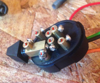
I purchased this switch from DCC. http://www.dimecitycycles.com/chrome-retro-horn-headlight-and-starter-control-switch.html. It is an Emgo switch part number: 46-68900. The switch I received would not perform the advertised functions. After an un-answered email to tech support I modified the switch to make it work for what I need. The switch is missing a wire that it needed to work properly.
Two of the contacts are connected underneath, I wanted these contacts to be my outputs for the 3 position part of the switch. This is what Ill use to control high and low beam and . I used a drill bit to drill through the connector piece on the bottom of the switch that connected the two outputs. I then relocated the red wire to the actual switch mechanism, this is now my input and the yellow and orange are the outputs for the high and low beam. The orange wire was added in and had to be soldered in since there was no pre-drilled hole or set screw to hold the wire in place
One of the green or black wires had to be re-located as well I forget which, but when the momentary button was pressed it was making contact with a terminal that didn't have a wire connected to it. I plan to use the two momentary buttons for horn and kill.
Over all for 15 dollars Id probably buy the switch again now that I know how to modify it. Also be warned that it doesn't come with a diagram. I am not sure what this switch is rated at amperage wise, but it shouldn't matter for my application since I am just running ground through it to trigger relays for each function.
Let me know if there are any questions.