My little kz440 project

Cool, it's a ltd too. Not a bad solution for the crooked frame either. Very red though :p
It also uses the same location for the rear sets as I had in mind. It's probably the best location.
 
So, a bit more work has been done, alhough not nearly as much as I would want. The wet cold weather isn't very conducive to manual labor involving shaping and welding steel, so I worked on other stuff mostly. The sun did come out at a few occasions though which prompted me to at least make some measure of progress.
While it was still dreary outside I set about attaching layers of foam to the now very stiff and solid seat pan. I cut some foam sheets roughly to size and glued them on using a weird type of spray glue that the upholsterer provided. I used some packing tape to hold the sheets in place while the glue dried.

49318190418_207aba0d24_b.jpg
]

I'm always quite sceptical of glue, but it's surprisingly strong stuff. It seems to hold up well.
I stacked on some more layers, and trimmed the outside edge with a bread knife, after which I ended up with this:

49318893367_dd5b639cc2_b.jpg


I know, it looks all manner of ugly and it's way too bulky. I wanted to have a lot of material to work with while I sand it down and sculpt the final shape. I am not a sculpter, so I need some material to allow for mistakes while I get used to the process. The upholsterer reccommended a powerfile for this job, which I ordered. It didn't arrive yet though, so this is as far as I got with that.

The weather improved a little by this time, so I got busy on some other small stuff. I had noticed that the allan key bolts that clamp the clip ons to the fork tubes interfered with the tank on the left side on (almost) full lock. On the right side it was fine. The bike must have gotten a good smack at some point, because one of the tabs that limit the steering movement was bent backwards a little bit.
I smacked it with a hammer in an effort to bend it back, but it didn't really look like it would budge easily. In the end I zapped it with the tig welder and some filler rod.

49318893362_002bcc08a8_b.jpg


It may not look the prettiest, but it's doing the job perfectly for now, making the pretty ineffectual zip tie that served the same purpose before completely obsolete.
I may revisit this at a later point if I decide it is not pretty enough.

49318190333_6347f44d02_z.jpg

49318190438_037fd51f1d_h.jpg


As it happens I had been working on my car as well that day, so I took the chance to make a picture of the two very different vehicles I own.

49318893287_2092078ca7_h.jpg


It may not look it, but the one in the back is quite a bit quicker than the one in the foreground will be. Both are lots of fun to work on though.

Lastly I wanted to see how the rear fender I had purchased would look like, and figure out what the best position would be.
So I propped it up using some wooden blocks, and after trying different stuff, this looked pretty nice to me.

49318190403_6c13d5d247_b.jpg


If I decide to go with this I want it to hug the tyre pretty closely, so I would be attaching it to the swing arm. It would also be adjustable so it can move with the wheel if that ever needs adjusting.
It would also provide a place to put a rear light. Still thinking about other directions I can go with this, but I will probably make a final decision when the lines of the bike become more clear with the saddle shaped, and the headlight mounted and stuff like that.

Here's another angle of it without the saddle on.
49318893217_3a23e3d700_b.jpg


I will have to ponder it for a bit.
Now I have to wait for that powerfile to arrive so I can finally finish that seat, hopefully I can start making a huge mess using it by next weekend.
 
Last edited:
before you do that mount, try it up under the hoop. It may look better, it may not but to me that looks to shorten up the back end too much. That also may change with the finished seat etc though as well. I like the fender itself a lot.
 
I will try it under the hoop, although I rarely like that look on a cafe. But maybe it will be different on this one. I agree that the fender isn't half bad, it came from caferacerwebshop aswell.

The story of today starts off with this fugly seat "blank" I made a while back.
49440711286_a141c5aeb9_h.jpg


The thing was becoming quite the eyesore, and my powerfile had arrived some time ago so although it was cold and windy outside I decided I could stand it no longer! I started with ripping off one layer, as I knew the complete layer had to go anyway and it would be way too messy to sand it all off with the powerfile.
49440238603_fdecda7ee0_h.jpg


Than came a lot of sanding, looking at the result, trying to decide how to improve it, sanding again, correcting mistakes, etc. etc.
As said, I am not a sculpter by any means, so it was a bit of a challenge.
In the end I was sort of successful.
49440238968_c4844e53f7_b.jpg

49440938542_49bc1acb71_z.jpg

49440711251_0faf09d80f_b.jpg


I didn't really want to touch it much more in fear of screwing it up. It's easy to find yourself in alternating between sides to correct for symmetry slowly grinding it down until you finally hit the seat pan.
At the last moment I did one last pass on it though, and I'm glad I did because it left a better finish. It started raining at that point, which I took as a sign to stop.
49440238813_f051f8d1c3_b.jpg

49440938492_7b91068635_c.jpg


This stuff leaves a mess when you sand it like I did. I didn't see a better way to do it though. I made sure most of the material that needed to be removed was cut off with a bread knife, and then only used the powerfile for the final shaping. The dust gets everywhere though, and it's statically charged too, so it clings to whatever it lands on.

I dropped the resulting shaped saddle off at the upholsterer where we discussed the color etc. He had a few reasonably nice imitation (skai?) leather in the color I liked. I showed him what I had in mind and we came to an agreement. He really gave me a handsome discount too. At the last moment he showed me some real leather samples he had in a book. We had discussed before that the real leather required bit more maintenance, and as it was quite a bit more expensive I decided just to go with the imitation stuff.

When I got home it was already bugging me..., the real leather did look significantly nicer than the fake stuff. I asked the upholsterer what kind of maintenance it exactly required, and it only needed to be treated with some wax like stuff 2 times a year. Not that bad after all I thought. He had also given me that handsome discount, so after adding the price of the leather the total was not much higher than I had expected to pay for the fake stuff.
It was on my mind for 2 days before I finally pulled the trigger, and I messaged the upholsterer that I went for the real leather after all. Funnily enough he may have been even more excited than me, as he really wanted to make that saddle with the real leather.
I'm glad I did... it really looks very nice

49440938447_daa55d8682_b.jpg


I couldn't wait to testfit it on the bike, and when I did I wasn't disappointed!

49440938367_e4a23257a5_h.jpg

49440238698_c52e708cff_z.jpg

49440238733_9f1c1f85ac_b.jpg


I think it looks gorgeous :eek:, really happy with the result.
I had temporarily fitted the engine and the exhausts as well, so the overall shape of the bike slowly starts to emerge. I have not decided on the color of the tank yet and I wont do so for a while I think, but the color of the seat is perfect.

Up next is going to be the rear sets, which is the reason I mounted the engine and pipes. I will be attempting to make my own, hopefully it will work out the way I have in my head.
 
Last edited:
Nice work on the subframe and seat matey. Can you find a 17 or 18” Kawasaki front mag rim, that will drop the front and give some proportion to the new seat angle?
Nice start to the build, well done.
 
I think the current rim is 18". I may be able to find a 17" one, not sure. I took the cap off the right hand side of the front hub and found it was prepared to take a rotor on that side as well.
I don't believe they all have this, and I think I may know a way to easily convert it to dual disc in the front.
I am considering to raise it slightly in the rear to get a bit more clearance between the tire and the frame. That may also help with the stance a bit.
 
The rear is 16" yes. An 18" rear would be nice maybe. I'm keeping an eye out for one, but I need to get some other stuff done first before I spend money on that. The saddle did kinda blow a hole in my budget for a while :p
 
That seat looks tremendous. I was noticing the belt drive setup Kawi ran for a few years on those. I'd be curious what it would take to do a chain/sprocket swap.
 
Chain sprocket swap is very easy on these. Just need to buy the 2 sprockets and the chain and it's a straight swap. The belt guard doesn't fit the chain, so you would need a chain guard as well. I like the belt drive though, just because you don't see it that much. It's low maintenance as well. New original kawa belts are unobtanium but I saw that there are belts available from gates for HD sportsters that fit these bikes. I think I will try to retain the belt drive system for now.
 
So I had cooked up a plan to create my own rear sets, as buying them is quite pricy and it's a nice project to build them myself.
This is the stuff I was planning to create them with:
49473964928_5206c6ce35_h.jpg

It's about 15 dollars worth of aluminium and ballbearings.

The first order of business was to use the minilathe at work to create some bearing cages for the little ball bearings.
49473964908_2dae780bab_h.jpg


Then I used a aluminium cutter in a jigsaw to cut out the levers from the aluminium bar.
It worked quite well to cut aluminium like that, much to my surprise!
After roughing them out with the jigsaw I used the powerfile to give them their final shape.
Here you can see one of the bearing cages with a bearing pressed in, and one of the levers that I plan to weld to the bearing cage:
49473964853_80c01ab744_b.jpg


Aluminium is a little harder to weld than steel, so the welds weren't very pretty. Nothing the powerfile couldn't clean up though. :D
The result is actually quite strong, so it should work fine.
49474673092_ec2d2f89da_h.jpg

I am contemplating to drill some holes into the lever to give it a bit more character, and to make them a little lighter.
Also I will give it a better finish when they are done.
After welding I drilled a hole for the rod end to connect to and mocked up the setup to try out the positioning.
49473964948_10d770e790_h.jpg

I will create a new mounting point for the rear set which is a little higher up so it will clear the exhaust when downshifting.
If I use the passenger footpeg mounting point it would have to be adjusted too far up as to not interfere with the exhaust, which makes the angle my ankle has to make to shift quite uncomfortable. It felt quite good in this position though, I think it will work out fine.
I will eventually buy some new rod ends and make a custom lever for the shifter axle so things will fit a little better. The forward controls these came with will still be a complete set I can sell then as well.
I couldn't do much more, because I need some material to make the new mounting point, and I still need to turn up toe peg for the shifter lever.

During disassembly of the bike I had noticed that the exhausts were in bad shape. One of them had quite a big crack through the seam where the damper meets the rest of the tubing, and the other had the part of the x pipe rotting off.
49474673057_059272a3a2_b.jpg

Well that explains the sound it made when I was putting around with it on the driveway :D
I wanted to try and patch them up for now as they are hard to find here for a good price. Also I like the fit of these on the bike.
So I ground off the chrome and the rust near the damaged area, and cut a strip off some sheetmetal. The plan is to wrap it around like this and weld it in place.
Most of the patch will be hidden under the bike, and I will probably wrap the pipes as the chrome had corroded quite a bit at places.
49474672977_777bc9a530_b.jpg

I was in the process of welding it in place, and tapping it into shape with a tiny hammer when I was finally losing the light.
I couldn't really see well enough to go on so I called it quits. The photo of the end result will have to wait until next time :)
I realize it will probably be a temporary fix, but hopefully it will hold for a while. When it eventually fails again I may make a custom set of pipes.
 
Last edited:
As I'm sitting here writing this blog entry I hear the soft sounds of rainwater finding it's way into my room, dribbeling down the wall and slowly soaking a stack of old towels. It appears that the ship has sprung a leak! No matter, I wont bail out just yet although I'm not the captain. Besides, I've got a blogpost to finish, and I still have dry feet so it's not all that miserable. I guess I will have to climb the deck tomorrow to check the freeboard. Hopefully it will be dry by then.

Many a thing has passed since I last posted an update to my musings back in februari. It was not a smooth ride by any means. The current mass affliction has affected us all, and though I have to admit I don't seem to have come down with it, at least not badly, it all seemed like a minor thing to me amongst the turmoil that had befallen us. I do realise it is not however, and I hope everyone here is either healthy or making a speedy recovery.

I seem to have left you with a shot of an unfinished exhaust patch, taken in the waning evening light. I have long since finished the patch with a series of tiny hammerings followed with some welding. I never stopped working on the bike as it keeps my spirits up. I need to work with my hands regularly to keep myself happy.
It's not pretty, but it is also hidden under the bike so I think this will do just fine for now:

50049893843_b91c792eb3_b.jpg


I was in the middle of the creation of a set of rearsets, and had devised to create some mounting points a little above the original rear footpeg mounts in a bid for more clearance. I created these from some round stock which I drilled to size for an M6 bolt, which is accepted by both the bearings in the rearsets and the footpegs I decided to go with. Just offering up the new mounting holes to the frame and zapping it in hopes of getting it in the ballpark wasn't going to do, so I made a little bracket out of an aluminium strip to hold it aligned with the original mounting point.

50050717467_7ca66c603e_b.jpg


A few minutes with the tig later and both where attached to the frame, and I think the alignment is near spot on. I will try to borrow some time on a friend's mig machine to give the weld a bit more substance.

50050717777_f976da69b7_z.jpg

50050463296_ec2961a017_z.jpg


I could then get the shifter side mounted up to see how the clearance was and I still wasn't happy with it. The shifter still was adjusted a little high in order to clear the exhaust, which put my ankle in a weird position. I decided to move on the the rear brake side first and ponder on it a little. The brake side didn't come out half bad as you can see here:

50049893428_4e19fe1592_b.jpg


This piece was modified to account for the new position of the brake pedal. It had to come in a little bit, and the lever had to be repositioned.

50050717397_0b4250556d_h.jpg


Of course at this side I had the same issue with the pedal not clearing the exhaust.
It was around this time that my dad suggested to take a big old hammer to the exhaust on the shifter side, and dent it to create some more clearance. After all, stock exhaust have such dents stamped in for the same reason. At first I didn't like the idea too much, but upon further reflection I decided to go out on a limb and try it. The current exhausts aren't in great shape anyway so not much to lose. I took a piece of round stock and used that to concentrate the blows in a more controlled manner so I could shape the dent a little better. It looks a little rough with all the markings I made still on it, but with some cleaning up I don't think it will look so bad.

50050717752_79fe7cc455_h.jpg
 
This alleviated the problem on the shifter side quite a bit although it still wasn't entirely to my liking. On the brake side I wanted the pedal to be a bit lower still for comfort, so the same trick wasn't going to work there. I was a bit at a loss, and was thinking of ways to solve the problem when my eye fell on the MAP gas torch standing on the desk. That thing is hot enough to braze aluminium, so I figured it could easily heat up the aluminium enough to make it a little more malleable. I clamped the brake side lever in the vice between some strips of aluminium and hit it with the torch. After heating it a while I could easily make a bend in the lever. I repeated the same trick to bend the tip over to align the toe rest with the footpeg so to speak. It worked like a charm as you can see here:

50050717352_5d40013ed3_b.jpg


No dent needed on the this side. I didn't regret putting the dent in the other side though, as the pedal comes out quite a bit like this. At the shifter side I still want to be able to switch positions easily without my big foot having to go around the footpeg too much. Having said that, I did repeat the excersize on the shifter side in a lesser extent to gain a little bit more clearance. They are just about perfect for me now, so I'm happy with that.

50050462906_2716aef37b_b.jpg


Speaking of toe rests, I had created one out of a piece of aluminium round stock by then. Here it is standing beside it's future brother:

50049893773_5ff81fc6d1.jpg


Somewhere during testfitting I noticed that the bearings in the rear sets where slowly working themselves loose, and where about to pop out of the bearing cages. Not very surprising of course, as it is only a friction fit (and not very good ones at that) so I came up with a plan to create some covers for the bearing cages. After creating the plates in the minilathe and drilling and tapping a million holes I came up with this result:

50049893323_aa6c803c88_b.jpg


Really happy with how that came out.
Putting it all together I ended up with this setup:

50050717707_5e1f15b29e_c.jpg


They fit me well as far as I can judge while standing still. They can still be adjusted quite a bit, so when I get to actually ride the thing I can adjust them to suit my needs. They also need some shiny new rod ends (although the steel strap on the brake side has a rugged look to it) and a better surface finish, but for now I'm calling it good. It was a bit of work to make them, but I learned quite a lot from making them.
 
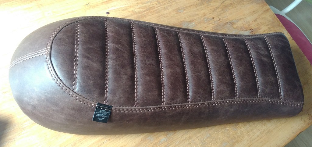
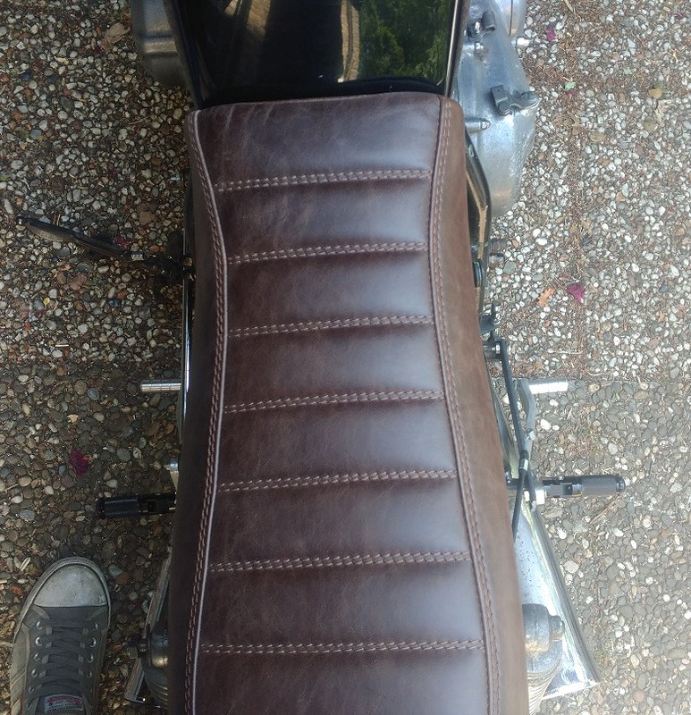
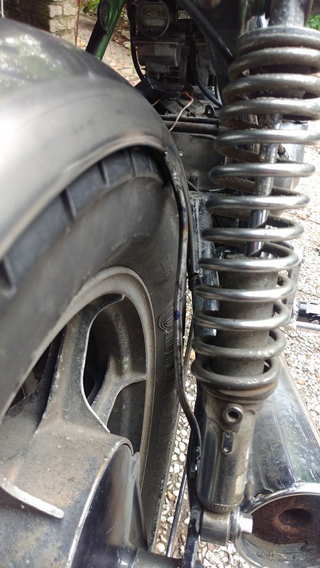
By this time I had made up my mind about the rear fender. I considered putting it up against the bottom of the seat, but I decided to go with the original idea to attach it to the swingarm and have it hug the tire a bit closer, kinda like this:

50049893768_7ab9c01be3_b.jpg


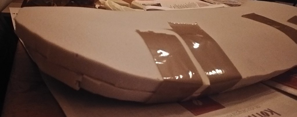
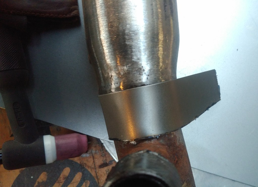
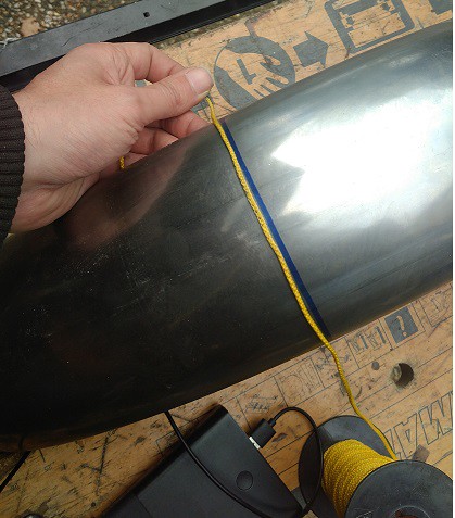
I cooked up a little trick to mark a straight cut across the fender. I first marked both sides to exactly the same length and then held a piece of string taut across the fender like this (Laplace should be helping us out here). You want the string to take the shortest route between the two markings so I moved it from side to side a little to help it get into position. Then a mark can be made along the string to get a perfect cut. Note that the last bit does require a helper.

50049893733_50ae42b00d.jpg


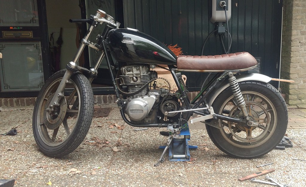
After cutting the fender I offered it up to see if I was anywhere close to the mark, and it looked quite good in my eyes:

50049893698_19cb68ab7e_b.jpg


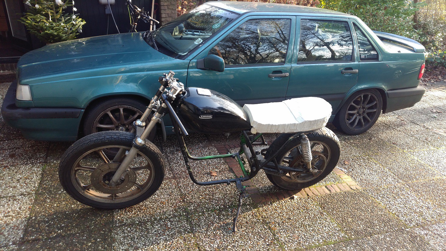
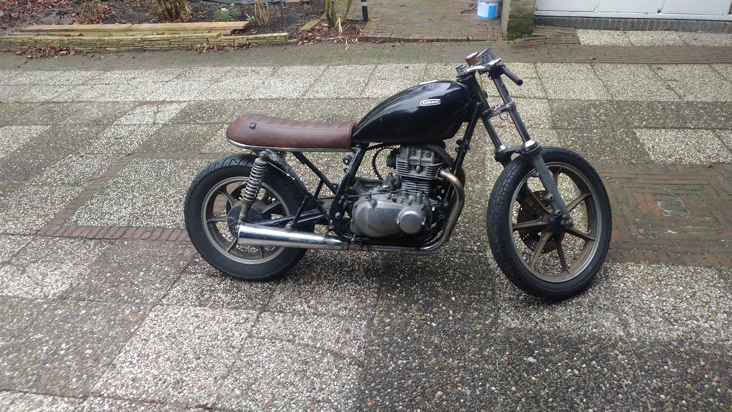
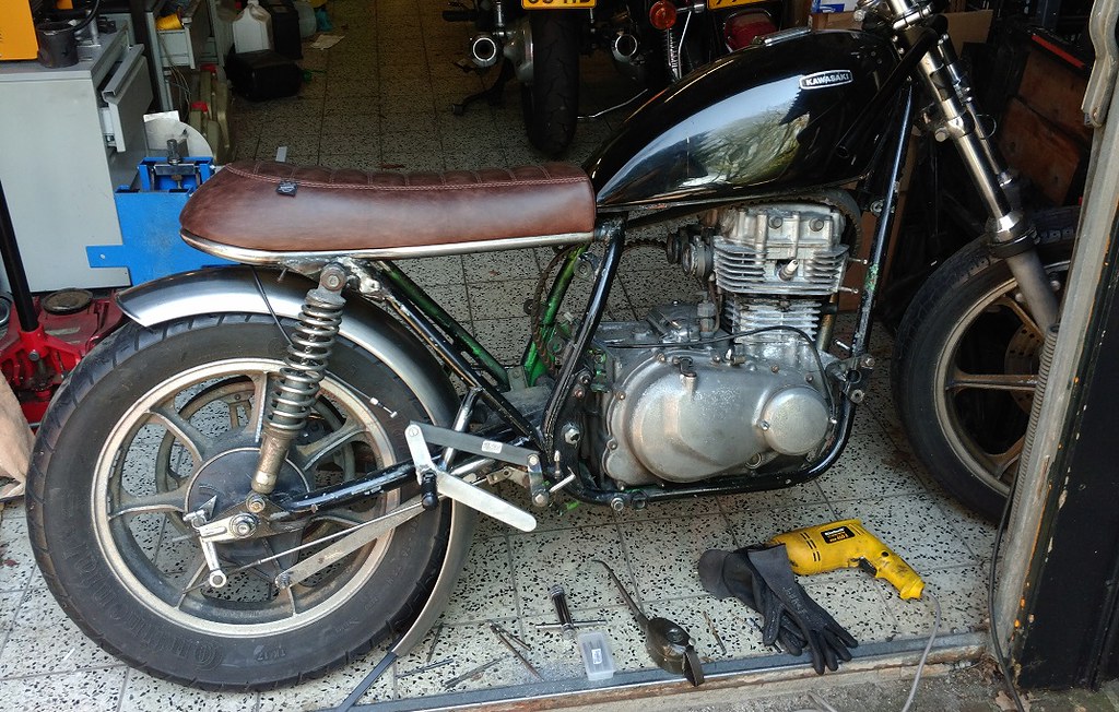
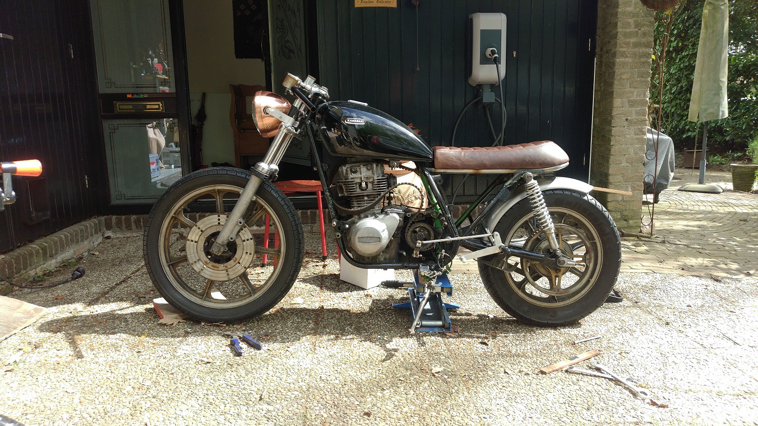
Suddenly, a headlamp appeared and attached itself to the front fork with temporary brackets.

50049893713_28d07baa71_h.jpg


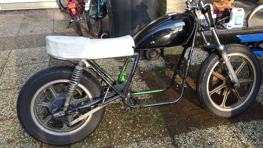
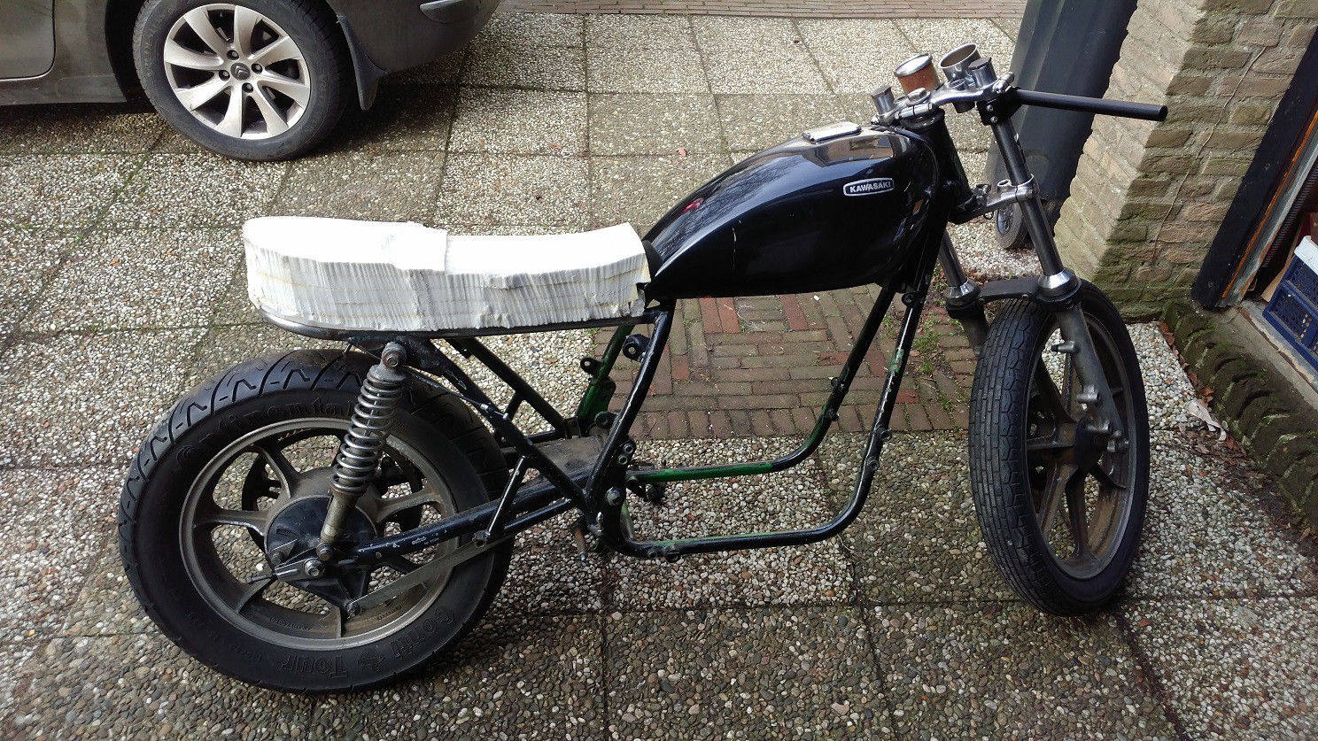
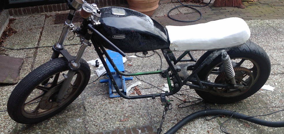
I'm really starting to like the shape this little bike is acquiring, even in the rough shape the individual parts are still in. I found myself staring at it for a while and dreaming of riding it:

50050463226_b7fd9eebbd_b.jpg


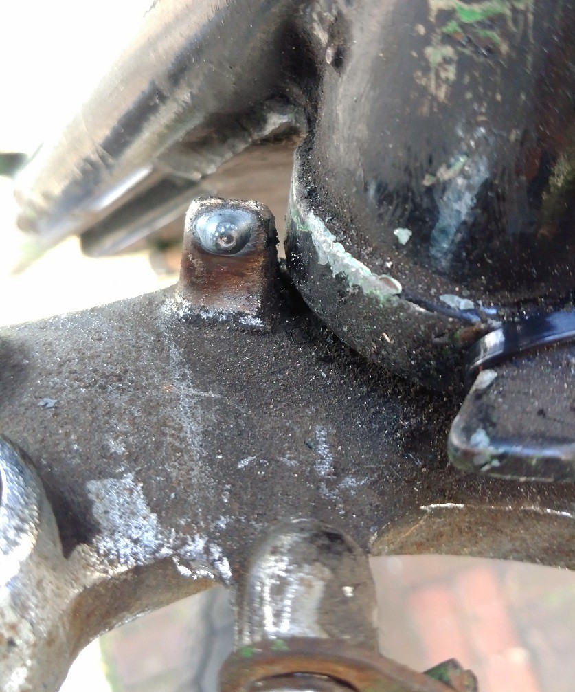
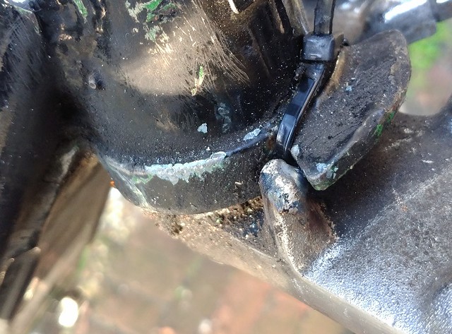
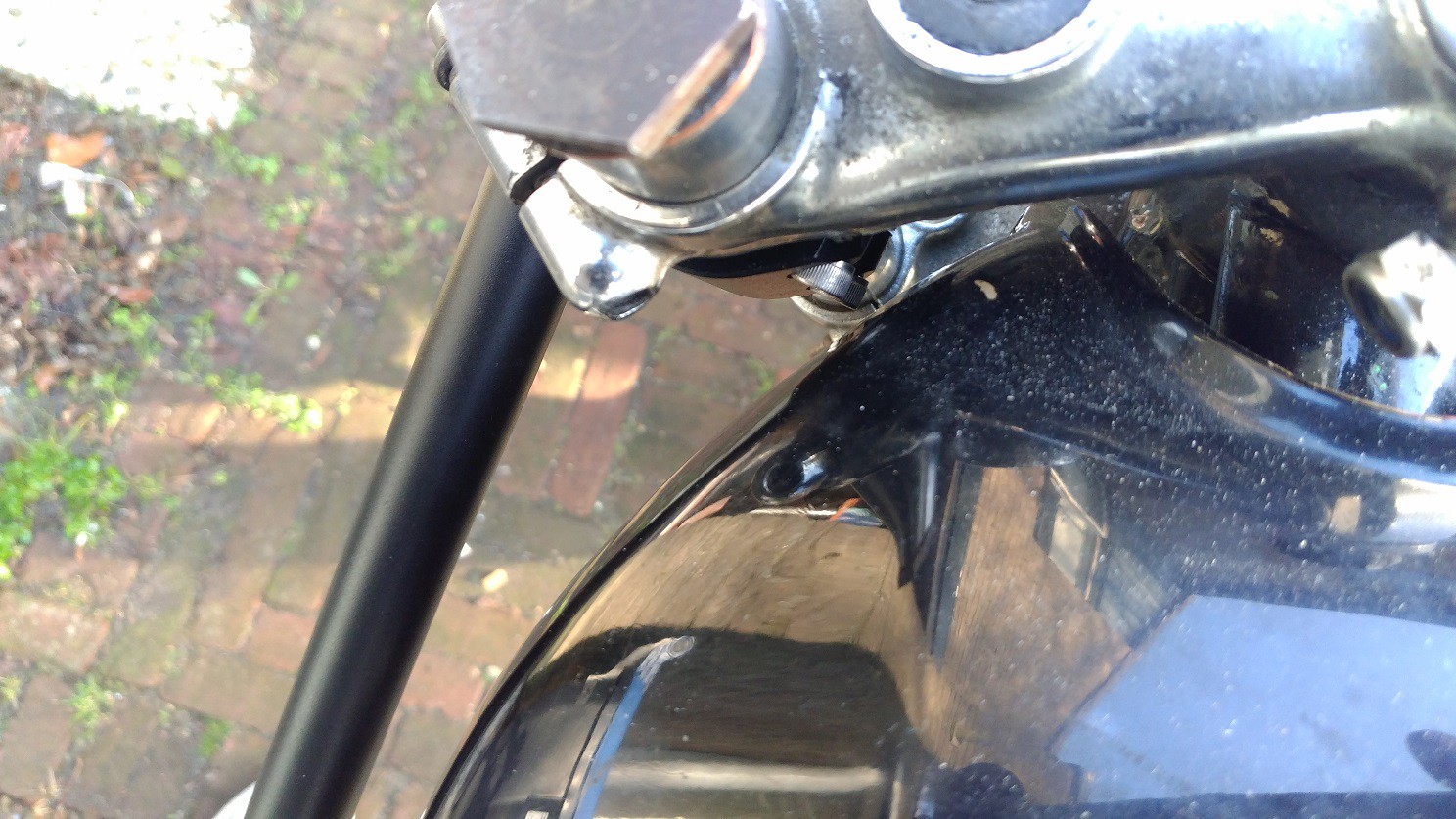
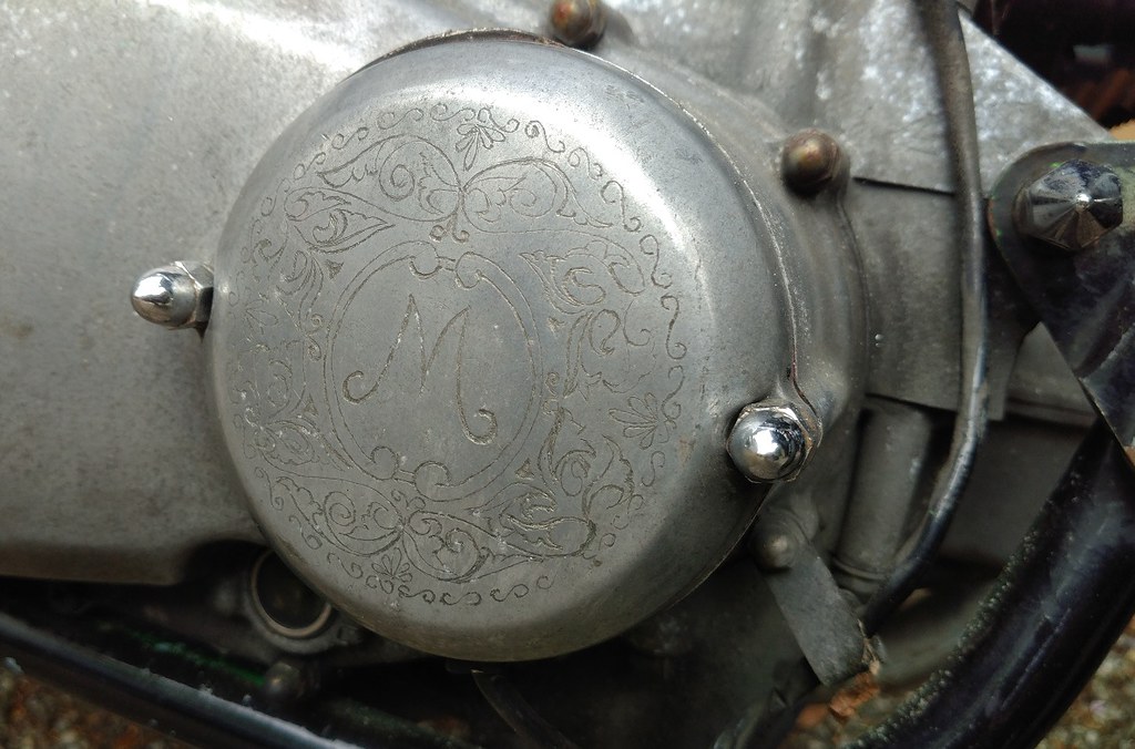
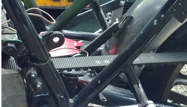
I also found this little gem on the ignition pickup cover which I had not spotted before (note the pointy fasteners still present at some places):

50049893603_684a8ac9b3_b.jpg


One of the previous owners must have done this at some point. It's a bit of a coincidence, as M is the first letter of my name. I will polish it up a bit, but otherwise keep it as it is. I think it's quite charming.

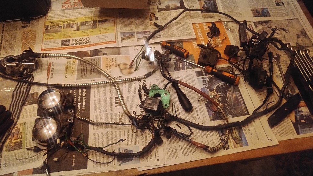
At this point it was quite a long time ago since I ran the engine. I really wanted to hear it run again, so I picked up the carborettors and the old wiring loom from storage.

50050717312_5c8bafca76_b.jpg


This 40 yr old loom is a mess, and I'm not going to use any of it, so I decided isolate the bare minimum required to make the engine run, and ditch the rest. I took a look at the wiring diagrams in the service manual and came up with the bare bones of the ignition, and starter motor wiring. I will put up a diagram of it if there is any interest.

I really like how they solved the problem of keeping the ign coil dwell time semi constant throughout the rev range, which is not self evident with the transistorized ignition. They must have been quite proud of it as it was described in detail in the service manual. I wont bore you with the details, but it's really neat stuff.

After retrieving the required bits from the old loom and hooking it all up I was able to start the engine and let it run for a bit. It started up instantly on the first go. It ran as beautifully as I remembered from when I first got the bike. No chain noise or anything like that.

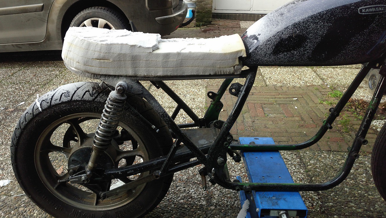
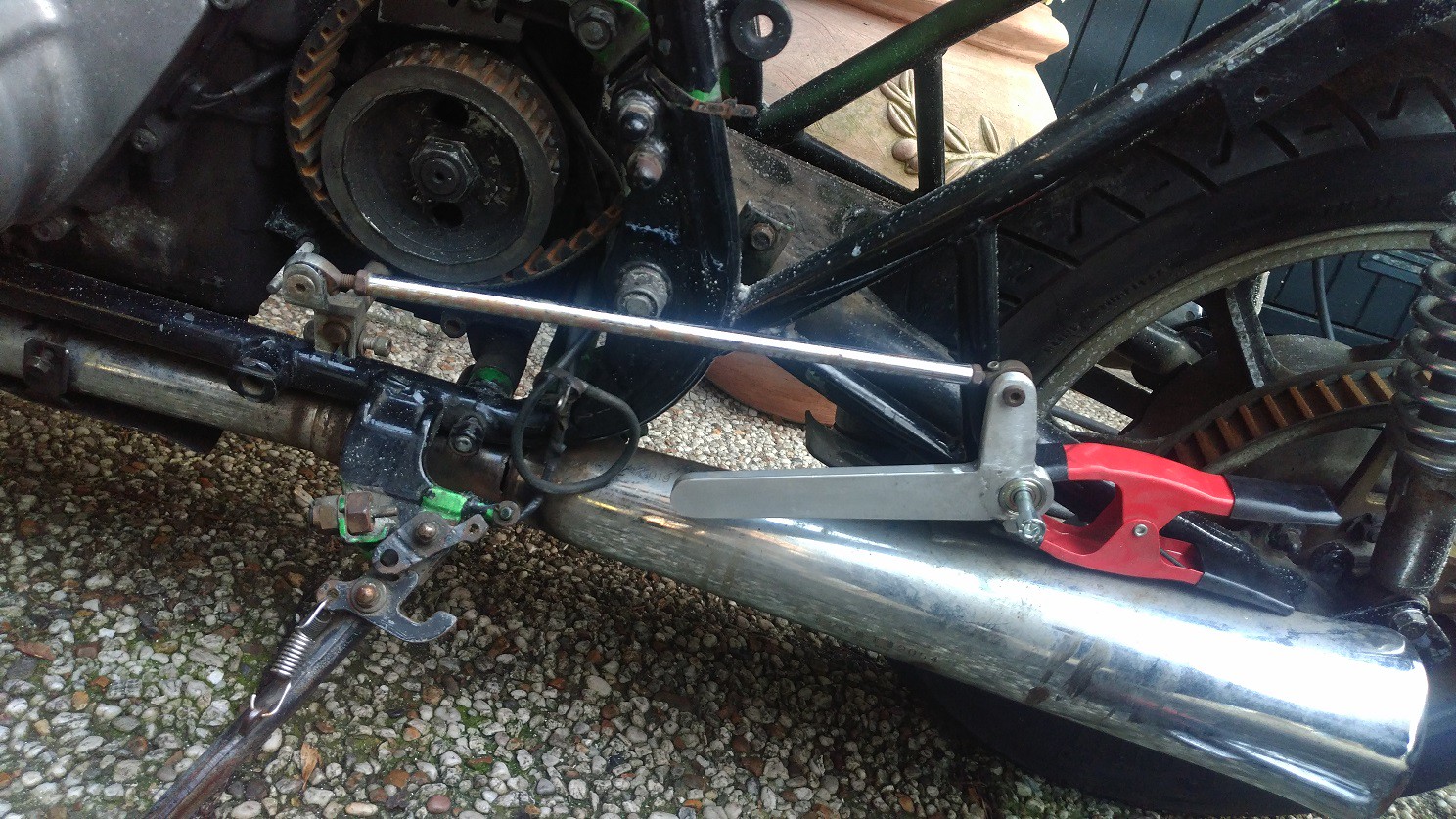
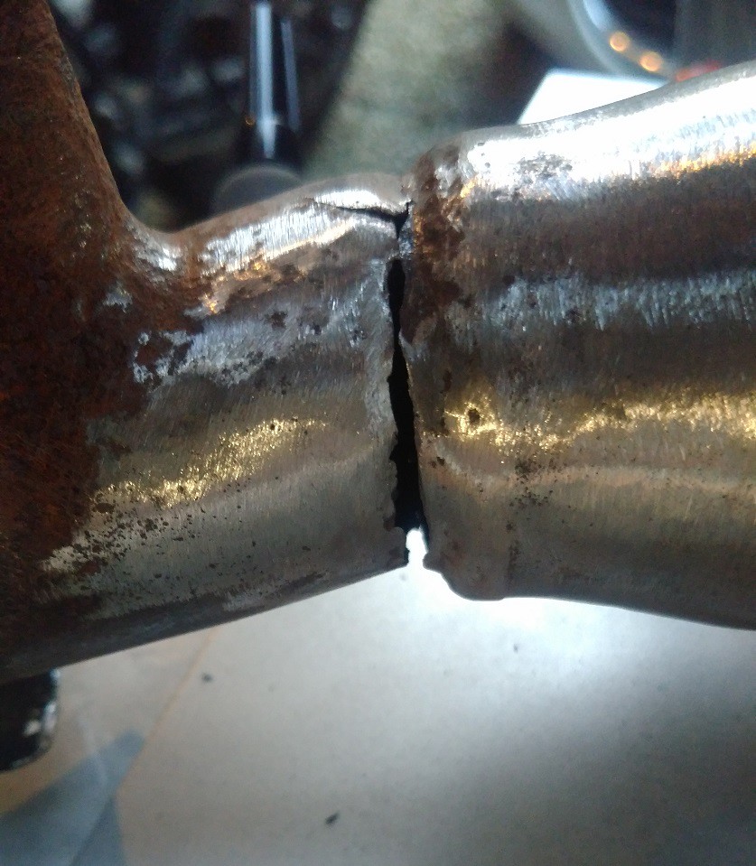
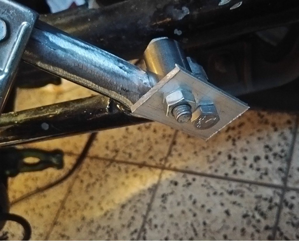
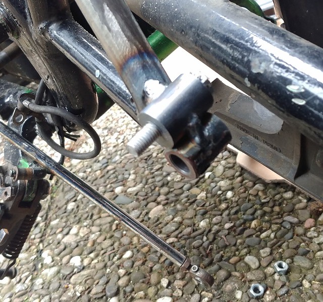
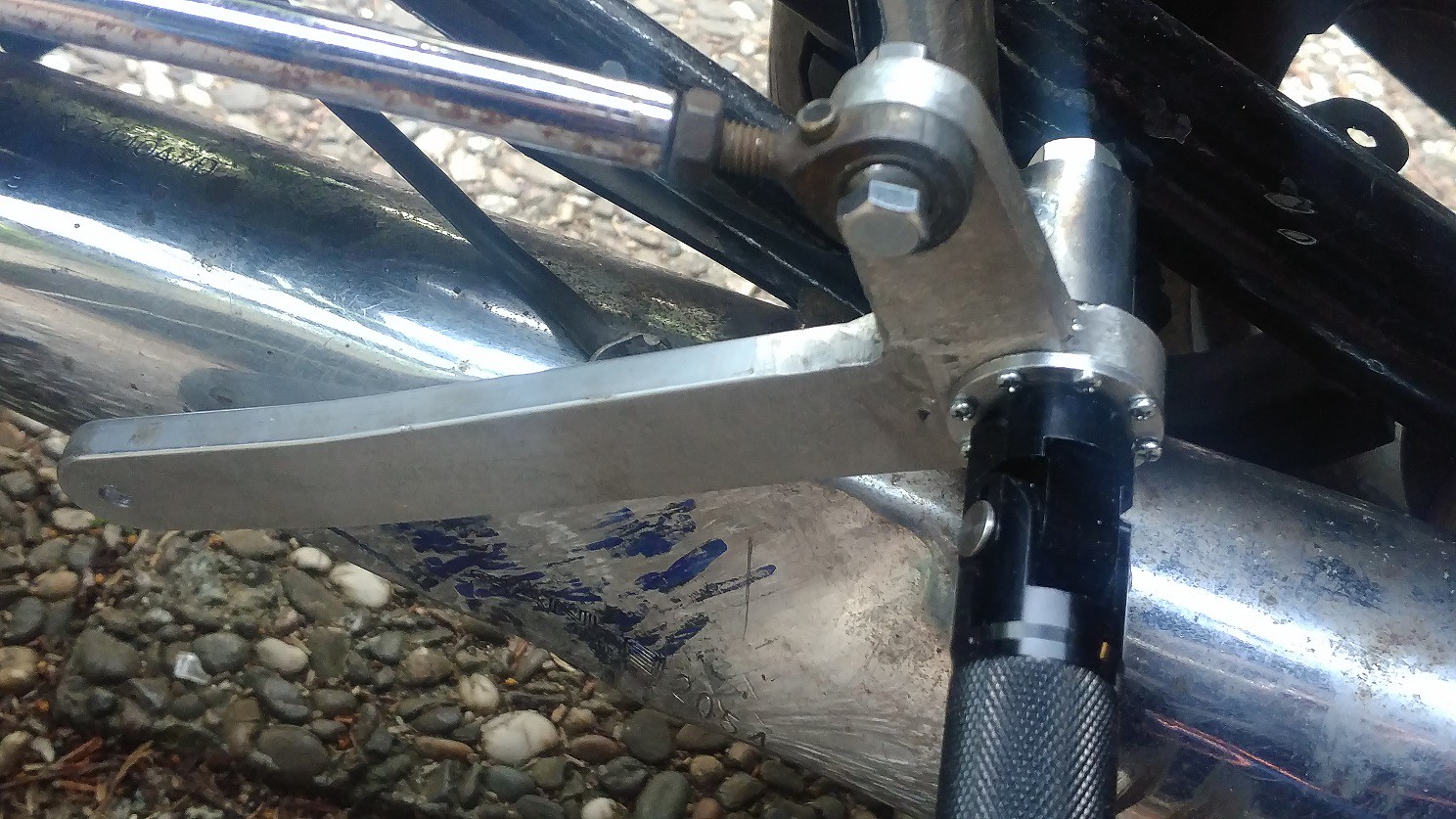
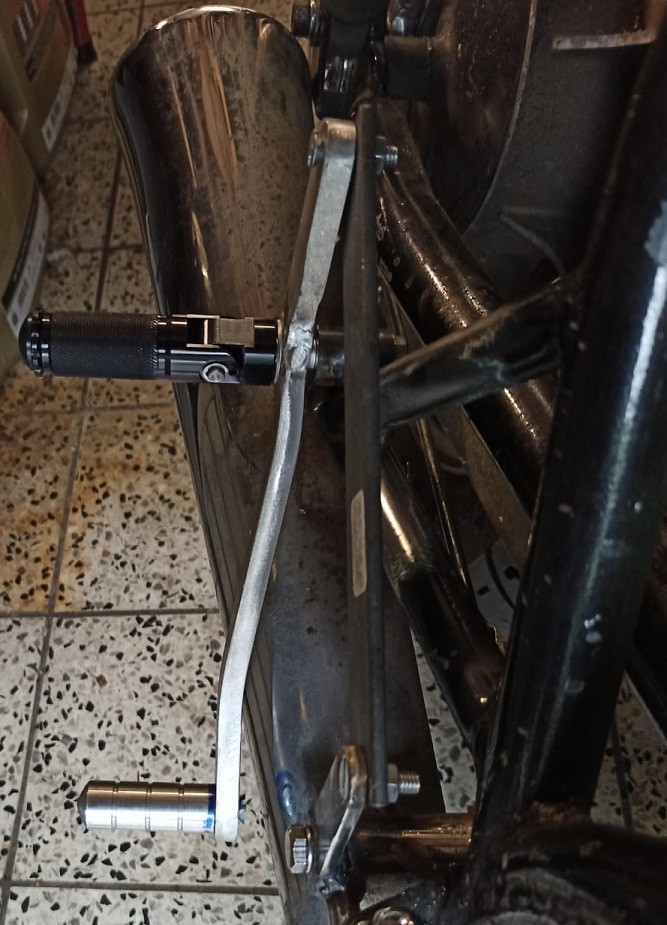
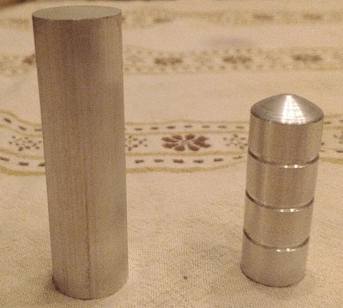
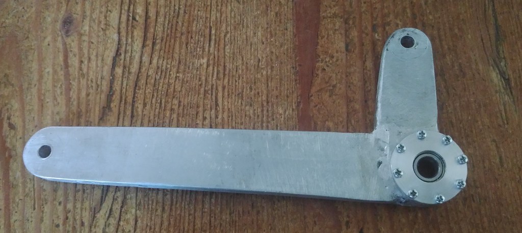
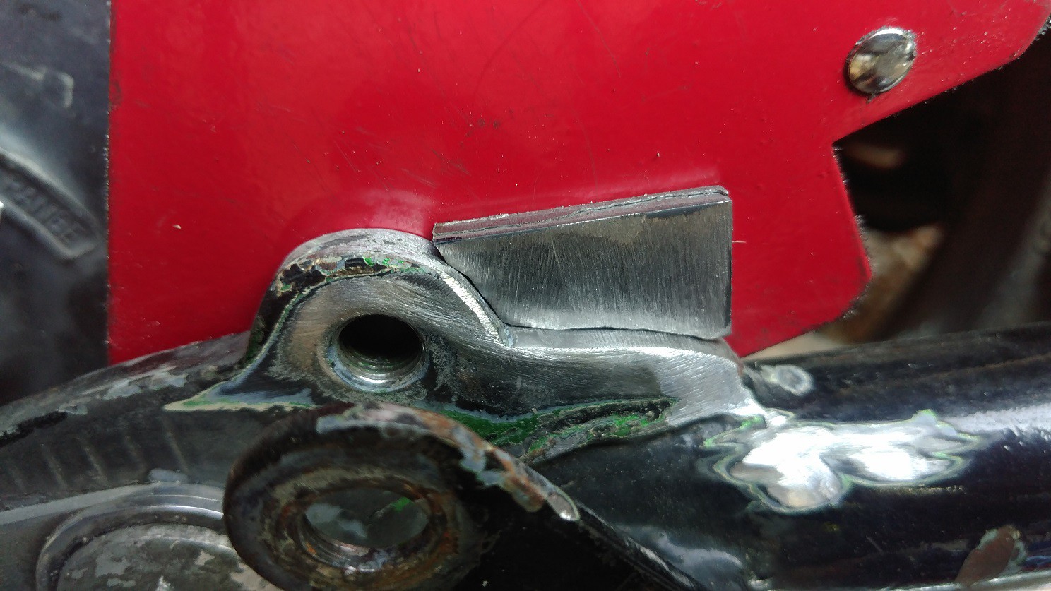
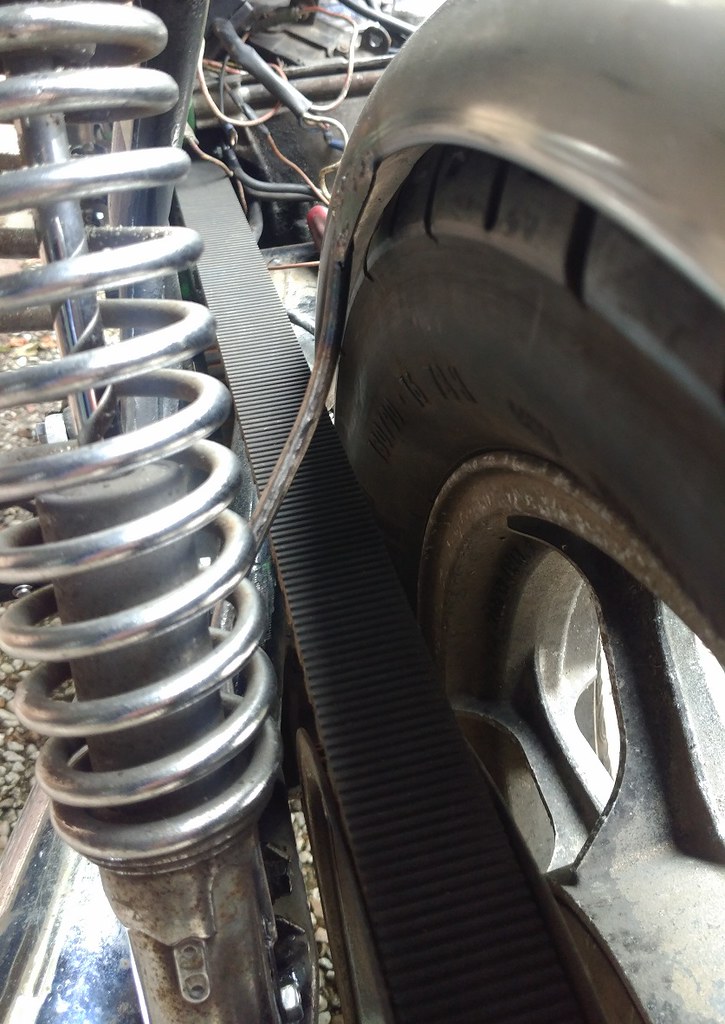
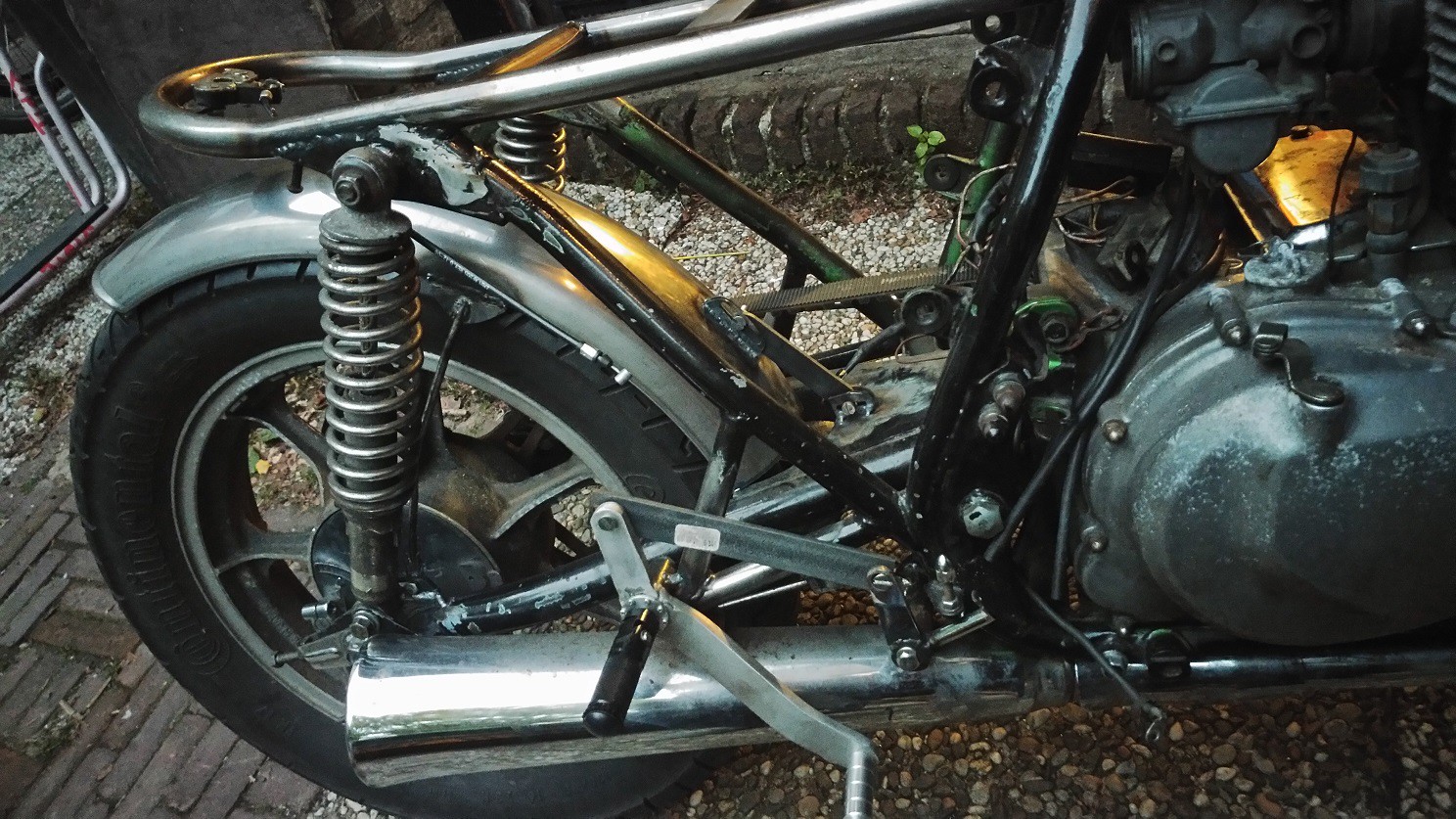
Next up was to create something for the rear fender to attach to. I wanted it to be adjustable, so it can move if the belt needs adjusting or if new tires are fitted. Looking at the swing arm I came up with a way to hide the side attachments behind the rear shocks. First I made some slotted attachment points on suitable locations on both sides of the swing arm.

50050463151_ed11f6c378_h.jpg

50050717572_86458ae2ce_h.jpg

50049893508_70fa494822_h.jpg


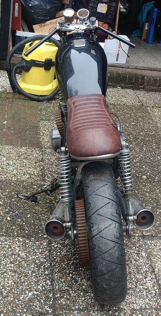
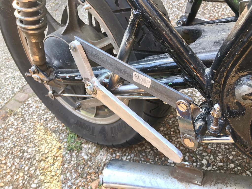
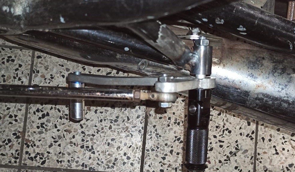
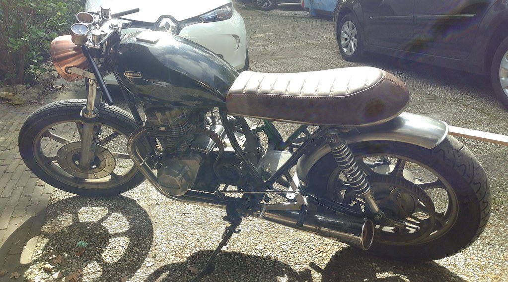
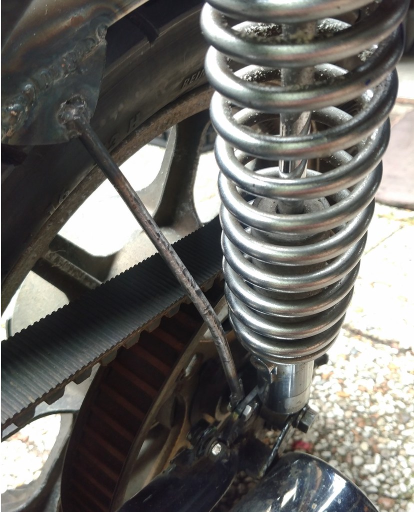
After creating a few more pieces for both the fender and the attachment rods, I ended up with this setup:

50050544526_1d0f360f47_c.jpg

50050798442_49b9f7f023_b.jpg

50050798432_785c20e78a_b.jpg


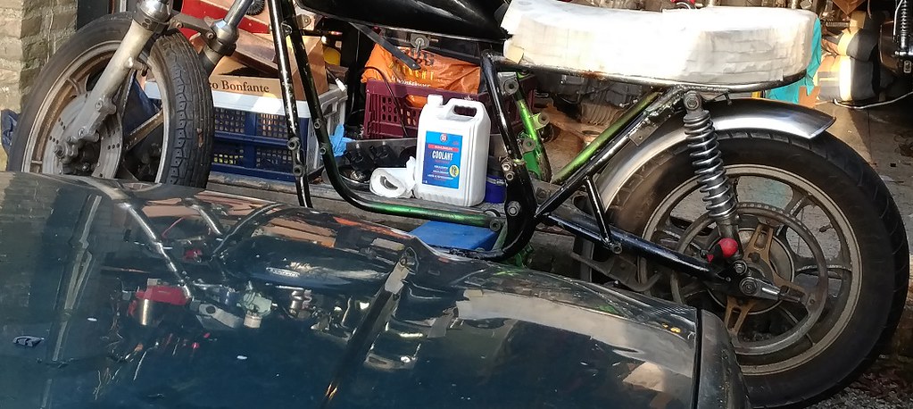
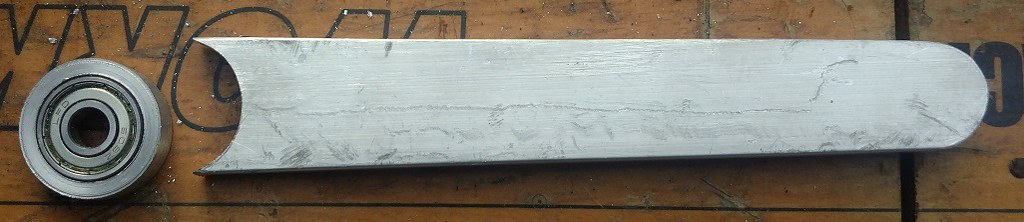
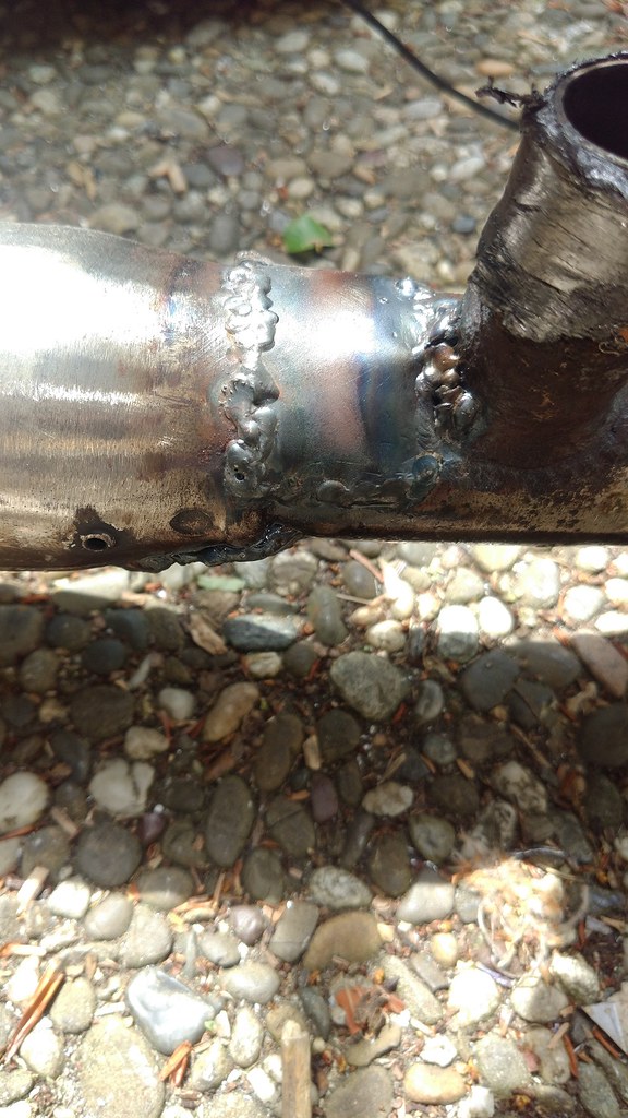
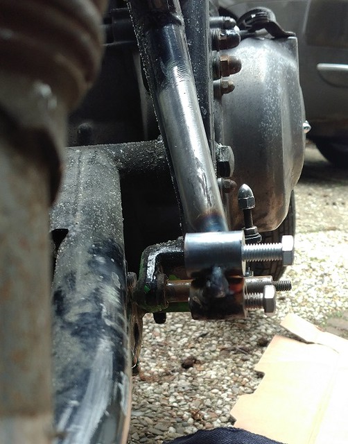
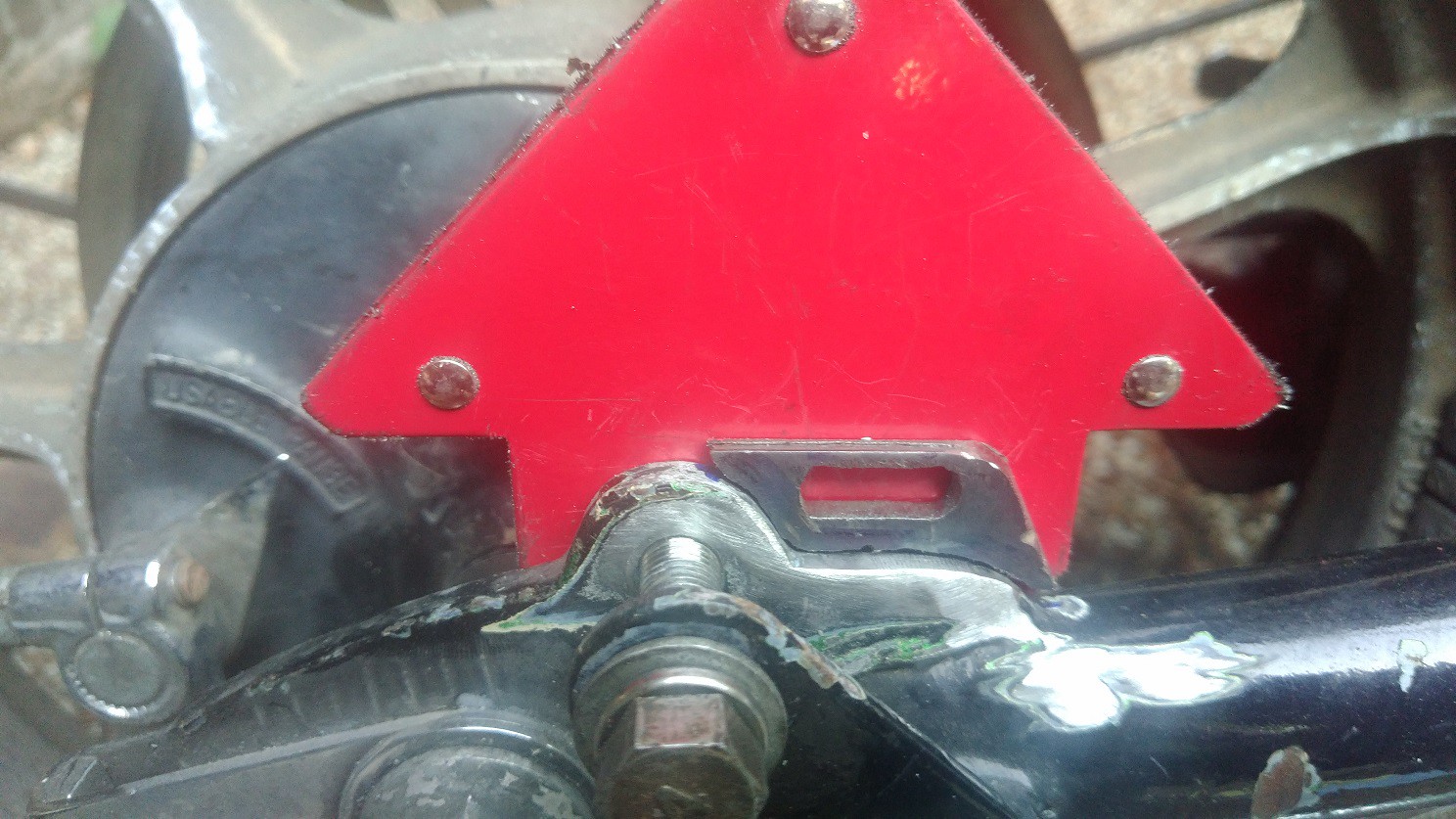
And that's where it sat for a while, as I had to deal with some car related stuff (ignition wiring was going bad). When the work on my car was done, I set about creating the front attachment point for the rear fender, for which I borrowed some inspiration from several pics on pinterest. After a bit of grinding and slotting I came up with this:

50050717527_843da3bba8_c.jpg

50050463051_cd847d4cfa_c.jpg


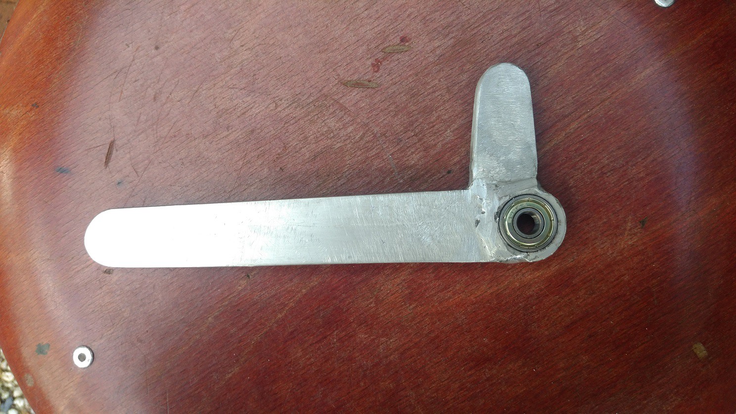
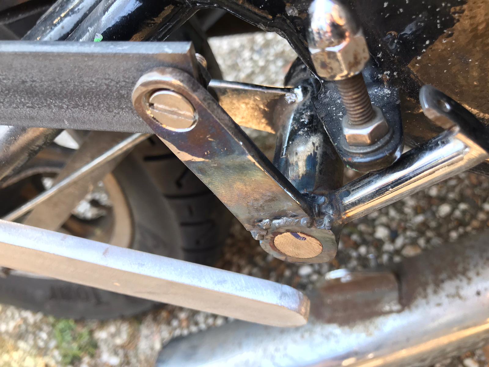
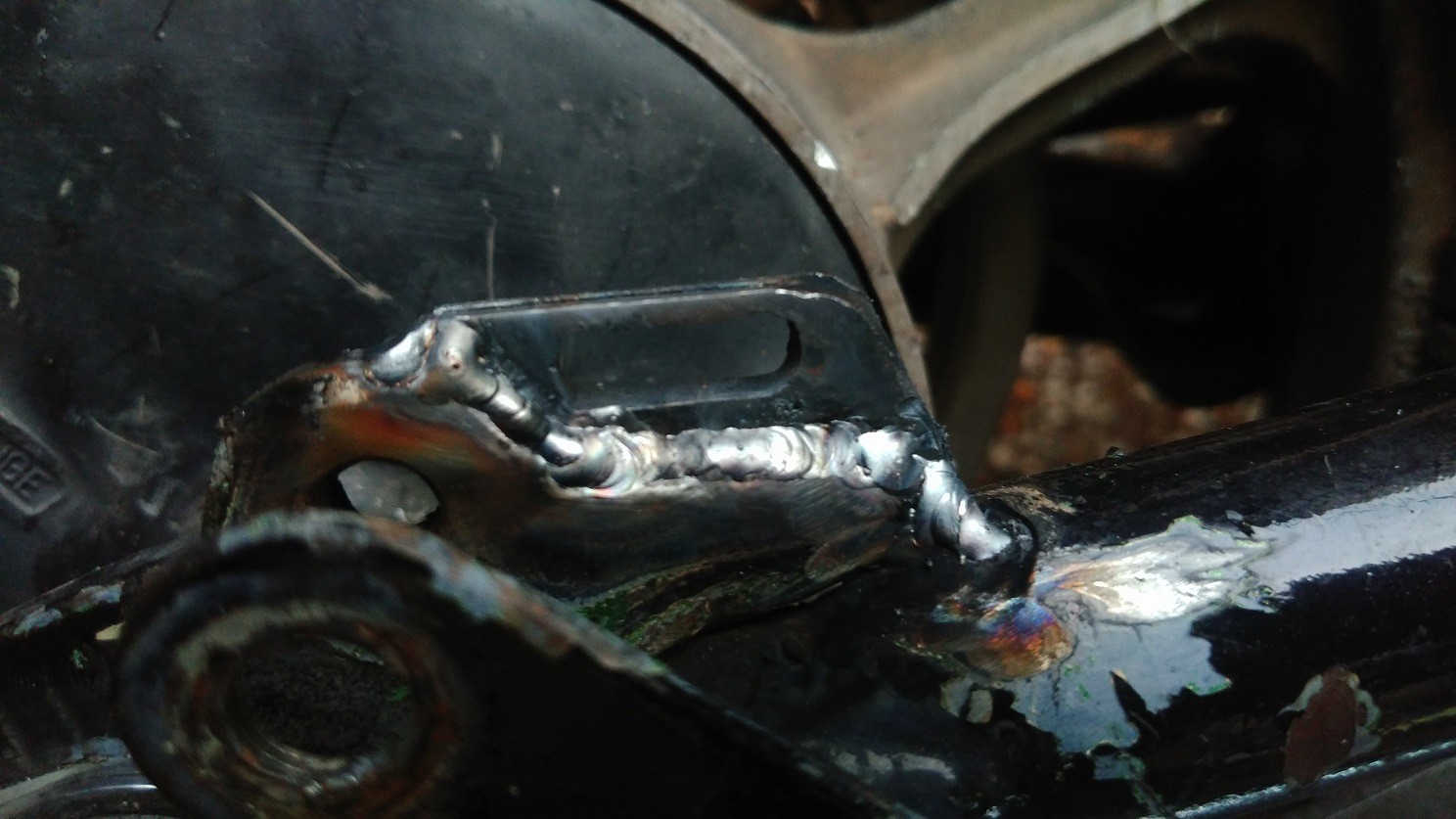
And here it is all welded in:

50050717287_7c45525622_h.jpg


Although it has modest clearance, it is possible to make the seat hoop meet the fender if you bounce it hard enough. That will not do, so I either need to find some rear shocks with less travel, or raise the rear a bit. The jury is still out on that, and it will probably largely depend on what is available. I'll have to make some measurements first to determine how much travel I actually have right now.

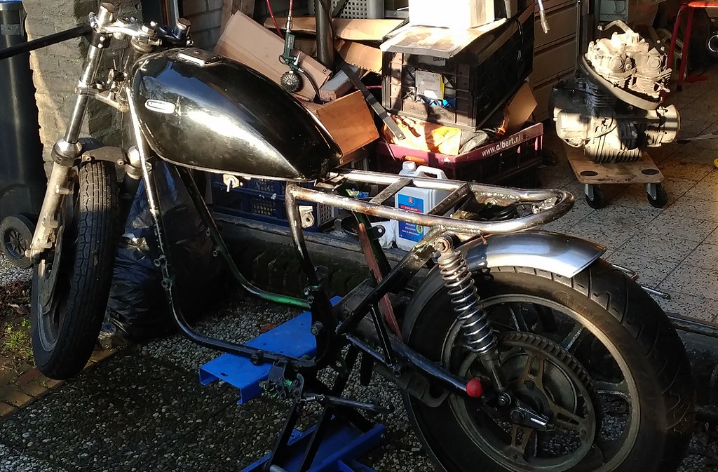
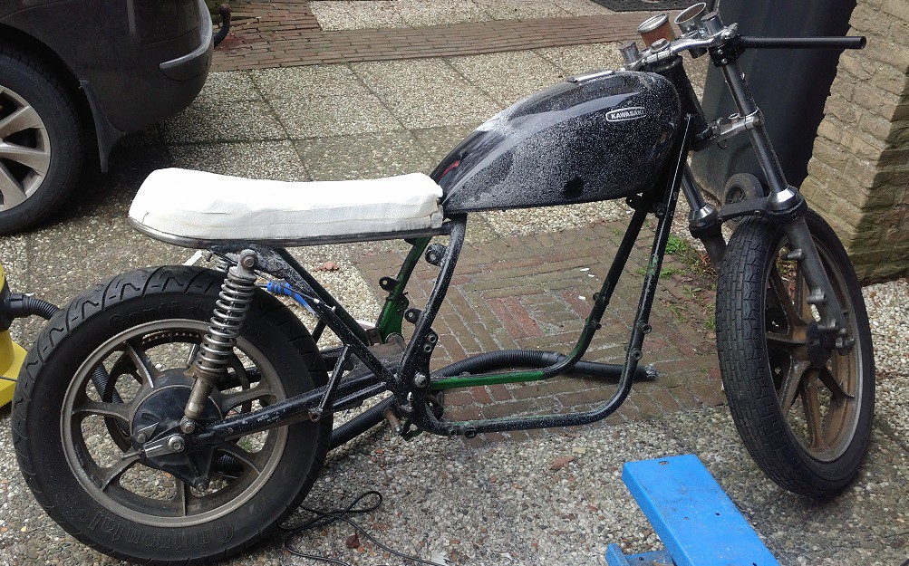
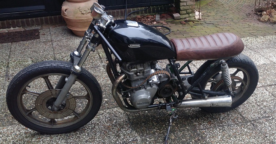
And that is more or less how it stands right now.

I'm trying to decide what to go for next. I'm ordering some parts from the US for the engine, and some other stuff, but that will take a while to get here. Maybe I will focus on the area under the seat, so I can get all the fabrication work on the rear of the frame done before I move on to the front. We will see.

Right, apperantly I have now written 3 posts worth of blog entry. That's what I get for not posting for such a long time. Hope I'm not boring you all to death by now.

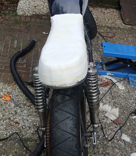
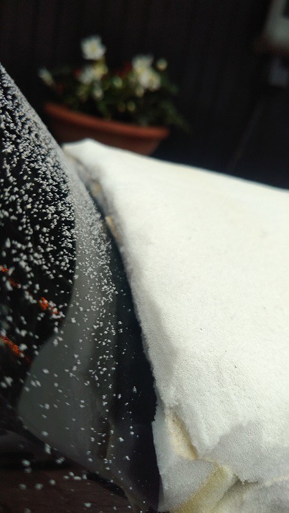
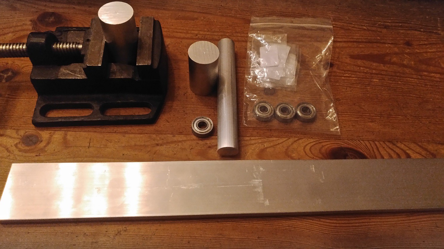
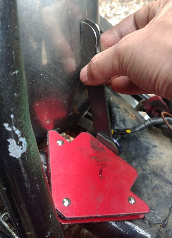
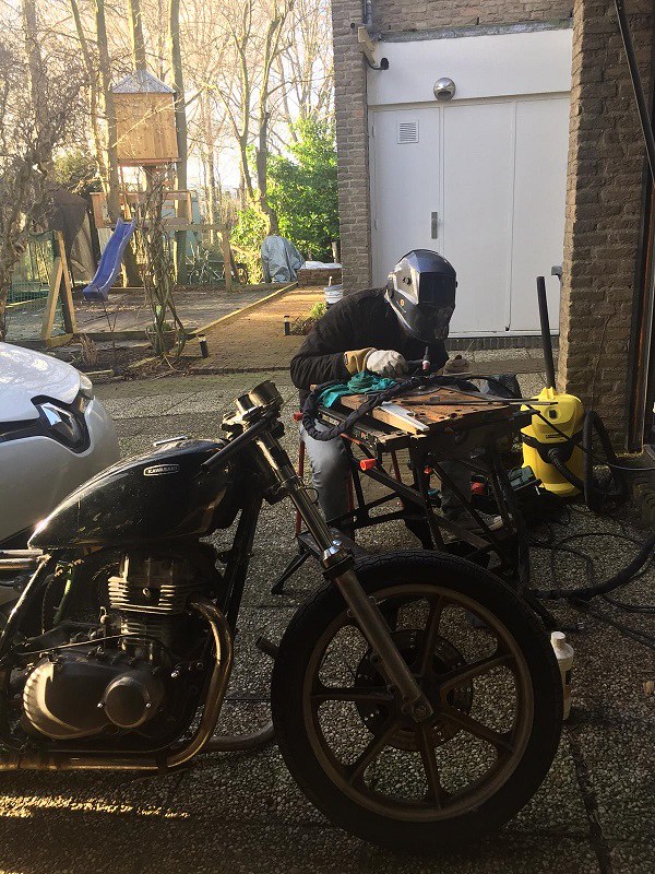
I will leave you with this picture, the creation of which I was quite oblivious to. The amateur at work... ;)

50050717222_c040d5c813_c.jpg
 
Last edited:
Back
Top Bottom