Follow along with the video below to see how to install our site as a web app on your home screen.
Note: This feature currently requires accessing the site using the built-in Safari browser.
We noticed you are blocking ads. DO THE TON only works with community supporters. Most are active members of the site with small businesses. Please consider disabling your ad blocking tool and checking out the businesses that help keep our site up and free.
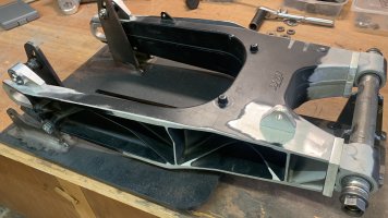
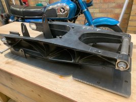
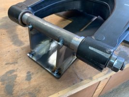
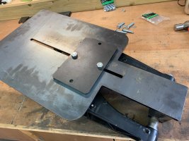
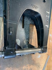
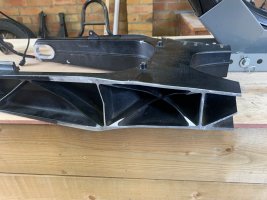
Mockup of how the jig will be assembled, then tacked together. I decided to only tack it, it is plenty strong, and it will be easier to cut apart and disassemble.
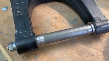
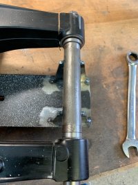
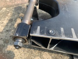
The swingarm pivot bolt needed some bushes to keep it centred in the 1" tube and on the M12 threaded rod, my neighbour made these on his lathe for me. they just press into the tube.
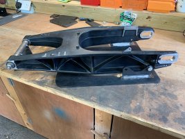
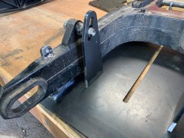
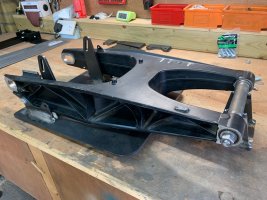
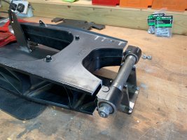
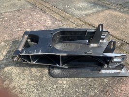
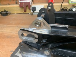
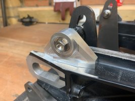
With the jig all tacked I could remove the swingarm from the bike and finish tacking the shock mount locators. They have a slot because I was not completely sure that my measurements resulted in a perfectly level swingarm with respect to the base, so this was easier. It won't matter if the shock mounts move up and down as long as they are in plane and equal front to back.
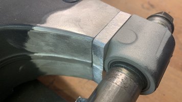
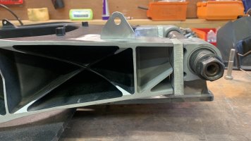
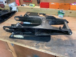
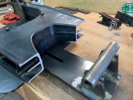
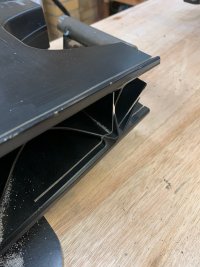
Cuts made on the bandsaw (no actions shots) and the final picture shows the result. I will cut some 10mm plate to go in between the gap and have it professionally welded.
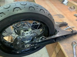
The reason I'm not sure this will work is because the swingarm is now interfering with the frame pretty badly, and material might have to be removed off of the swingarm to make it clear, necessitating side plates on the swingarm etc. We'll see how it looks when I tack it together and try to make it fit.
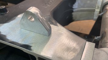
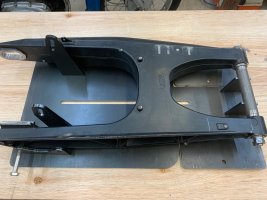
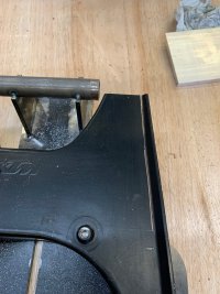
I needed to reduce the width of the swingarm so it would fit in the frame. I used the bandsaw again and took a few mm off each side, and blended it with a sander.
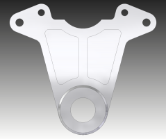
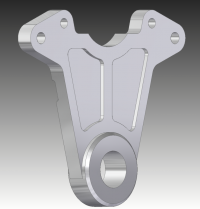
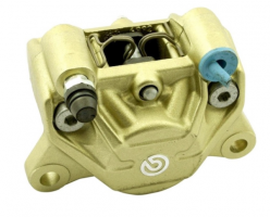
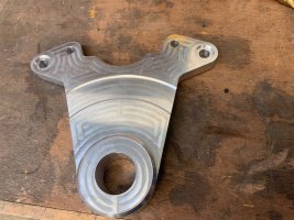
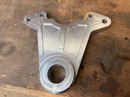
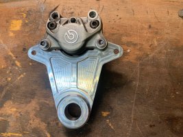
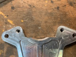
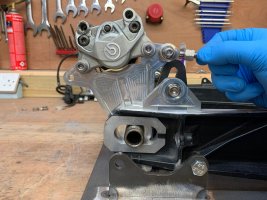
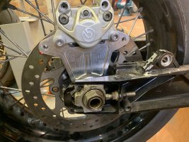
Mostly completed the new caliper bracket. Need a new one because the original will foul the shock. This one will use a heim rod end brake stay instead of locating on the swingarm as original. I haven't decided whether to put the bracket above or below the swingarm, so I've made it 'double sided' with respect to the brake stay mount. Once decided, I will mill off the extra brake stay mount. The bracket is designed to fit the Brembo P32. The diameter relief on the back is to clear the brake disc mounting bolts.
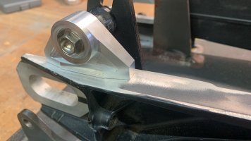
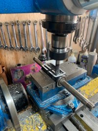
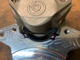
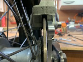
The parts arrived, yay! They don't fit, boo! No biggie, I had to remove some material to clear the pads. When I mocked it up and measured I didn't have the pads in the calliper body, and didn't consider that the pads might extend past the body. I did a shit job with the material removal, bit no one will really see it. I'll clean it up with a file after I do a mockup. Also I threaded the holes.
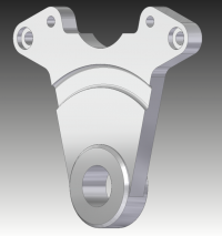
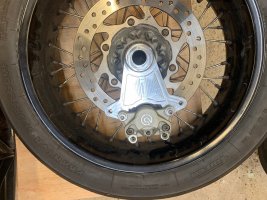
I'm leaning towards an underslung calliper, below the swingarm. Note that in this case, the left side boss will be removed, as the brake stay would utilise the right side boss.
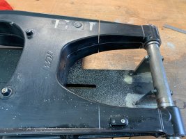
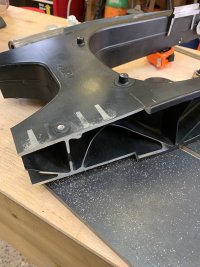
That solid alloy plate near the pivot is going to take a ton of heat to weld properly and i would be worried that the bearing bore will distort. Have you considered machining new pivot points and welding those on instead of resuing the stock ones? I undersize the pivot and machine the bores after welding so i can ensure concentricity and roundness of the bores. Not trying to be rude, just wondering if this had been considered.
That solid alloy plate near the pivot is going to take a ton of heat to weld properly and i would be worried that the bearing bore will distort. Have you considered machining new pivot points and welding those on instead of resuing the stock ones? I undersize the pivot and machine the bores after welding so i can ensure concentricity and roundness of the bores. Not trying to be rude, just wondering if this had been considered.
Hi Doc,
I considered having new blocks machined as you said, but decided to gamble on this approach just due to the expense. I hope it works! The welder (a coded welder, not me) will weld the plates first, and if they fail in some way, I'm only out the £70 I paid for the swingarm, and my time of course. If it looks like the bearing bores are still round, then we'll move on to the shock mount blocks.
The solution of the plates is also ugly, but it will all be hidden between frame members and behind the side covers, so it won't really matter. The welder is coming to see the jig tonight, I'll let everyone know if he can do it!
Thanks guys for your comments and support! The plan is to get the new swingarm finished, put it back together and road test it, then over the winter do a full teardown and paint etc. Getting there!
This site uses cookies to help personalise content, tailor your experience and to keep you logged in if you register.
By continuing to use this site, you are consenting to our use of cookies.