1979 CB750K m-unit blue ignition wiring

ceisen

New Member
I'm having troubles figuring out exactly how to wire up the ignition on my 79' cb750k. I've exhausted the internet and haven't been able to find a forum thread or wiring diagram that has gotten far enough to break down what I'm looking for.

The basics:
1979 CB750K
M-Unit Blue
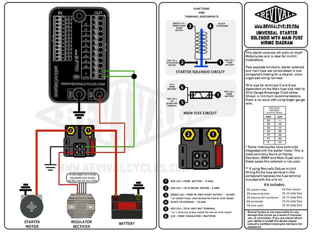
Revival Cycles starter solenoid w/ main fuse

Simple enough right?

My problems:
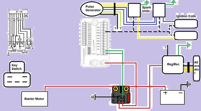
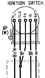
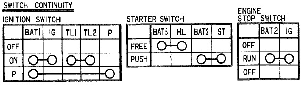
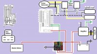
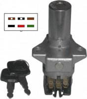
I'm using the stock ignition key switch BUT don't know what the wire inputs are on it, it was already taken apart and there was no connector on the wiring harness. All the wiring diagrams I've looked at don't give any clue (as far as I can deduce) as to which wire goes to which male spade. It's a 5 pin connector which I have represented in the wiring diagram below. Ideally (as with every bike) I'd like the key to initiate power to the m-unit so I figured that power would have to run from the starter solenoid or m-unit battery terminal to the key switch then to the lock input?

All my inputs and outputs for lights, brake lever/pedal, aux lights are working on the m-unit (if i connect the battery directly to the m-unit and a wire from there to the 'lock' input). So I didn't bother including them in the diagram below.

I thought I was making some progress when I had the ignition side of things hooked up but as soon as there was power to the m-unit and the kill switch was moved from "stop" to "run" the starter motor immediately kicked on. So I decided to remove all inputs and outputs and seek some help in fear of creating a toaster.

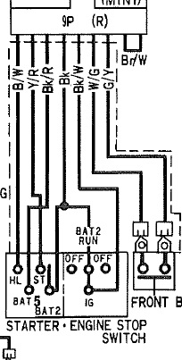
As far as I can tell the important wires from the hand controls are Black, Black/White, and Yellow/Red?

The only other outstanding wires that I don't know about are the black wire from the reg/rec, the light green from the pulse gen (I know it's the neutral indicator but can't figure out for the life of me where to route it to) and the black wire from the pulse gen.

Any help would be appreciated, or just shove in the right direction. I can't quite wrap my head around the rationality of wiring circuits

Cheers!

79-CB750-K-m-unit-blue-wiring-diagram-grey-background.jpg


hb-start-stop-switches.jpg


ignition-switch.jpg


2-0-starter-solenoid-wiring-diagram-97897-1528512605.jpg


Switch-Continuity.jpg


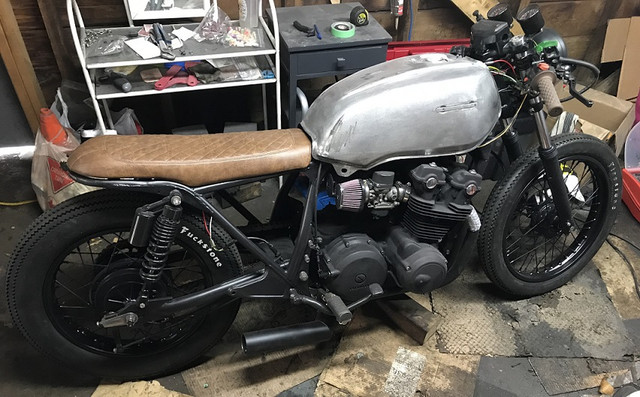
It's getting close...ish

IMG-0706.jpg
 

Attachments

  • 79 CB750K m-unit blue wiring diagram -grey background.jpg
    79 CB750K m-unit blue wiring diagram -grey background.jpg
    166.1 KB · Views: 4,998
OK... for the ignition switch, I think this is the correct graphic (attached). We're concerned about the red and black wires only. Others will not be used.

Are you using the M-Button at all or just the M-Unit? This will determine how the control wires are used.

There should be two black wires from R/R. The spare one in your picture should go to the AUX1 output from the M-Unit.

Neutral wire doesn't pass through the M-Unit. It should connect to the neutral light bulb up at the front of the bike (an extension will almost definitely be necessary).
 

Attachments

  • ignition switch2.jpg
    ignition switch2.jpg
    38.7 KB · Views: 708
Also, the black wire from the pulse generator is probably the oil pressure switch. Hooks up the same way the neutral light does, but to the oil pressure light instead.
 
Sonreir said:
OK... for the ignition switch, I think this is the correct graphic (attached). We're concerned about the red and black wires only. Others will not be used.

Are you using the M-Button at all or just the M-Unit? This will determine how the control wires are used.

There should be two black wires from R/R. The spare one in your picture should go to the AUX1 output from the M-Unit.

Neutral wire doesn't pass through the M-Unit. It should connect to the neutral light bulb up at the front of the bike (an extension will almost definitely be necessary).

The ignition switch in that image has 6 prongs where as mine only has 5 (the middle upper prong does not exist on mine). But it would be fair to say that it would be the same output?

I am not using an M-button for this setup.

The only black wires from the reg/rec are the one that connect directly with the alternator in the 5 min connector and the one (that is not hooked up) that is within the three pin connector along with the green ground and white/red (that I've indicated as red on my makeshift diagram) that connects to the starter solenoid. Regardless that black wire should go to then aux output? I've seen some wiring diagrams where it is connected in with the wire running from the ignition key to the lock input.
 
I accidentally posted a pic of the CDI ignition, but I think the red and black are in the same spot? You should verify with a multimeter. You're basically looking for two pins that have continuity when the switch is on and no continuity when it's off.

For the controls, black is now grounded, black/white to the KILL input on the M-Unit, and red/yellow to the START input.
 
Sonreir said:
I accidentally posted a pic of the CDI ignition, but I think the red and black are in the same spot? You should verify with a multimeter. You're basically looking for two pins that have continuity when the switch is on and no continuity when it's off.

For the controls, black is now grounded, black/white to the KILL input on the M-Unit, and red/yellow to the START input.

So i've re-done and cleaned up the initial image I posted. Is this what you're referring to?

Is that key ignition what I'm looking for? In terms of black to lock and red spliced off of the wire from solenoid to m-unit battery power?

79-CB750-K-m-unit-blue-wiring-diagram.jpg
 
So I was able to get everything hooked up, the key works, the ignition is powered everything is good (Thank you!) except that the kill switch is functioning backwards.

That is to say when it's in the switch is in the "run" position it's actually functioning as kill (confirmed on the m-unit as well), and when the switch is in the "off" (or kill) position it's actually to functioning as run and the starter switch works and the ignition output on the m-unit is engaged.

Yellow/Red is to start input
Black is grounded
Black/White is to kill input

Looking at the original wiring diagram I can't see why it would be backwards. Is this just something I'll have to deal with?

hb-start-stop-switches.jpg
 
Black/white from the handlebar is going to the KILL input on the M-Unit, right?

Then black/white from the spark units and the ignition coils are on the KILL output?
 
Sonreir said:
Black/white from the handlebar is going to the KILL input on the M-Unit, right?

Then black/white from the spark units and the ignition coils are on the KILL output?

yes black/white from handlebar is going to kill input.

black/white from spark units/coils is going to ignition output. There is no "kill" output.
 
Ignition output is correct. Sorry.

A quick check with the multimeter might be in order. With everything turned off, measure continuity between the black/white input wire and ground. You should get no continuity.

Next, flip the kill switch to run but keep everything else turned off. There should be continuity now.

If both of those things are correct, it's probably a config setting in the M-Unit that has to change.
 
You may have to either run a relay or more simple re-solder the wires on the kill switch...most hondas are kill switched, break run, make kill as they earth out the coils/cdi unit that prob wont work :)
re read your posts.... Pretty much ignore the above....move along nothing to see here :)
 
wozza said:
You will have to either run a relay or more simple re-solder the wires on the kill switch...most hondas are kill switched, break run, make kill as they earth out the coils/cdi unit

This is only true for the CDI models (twins from 1978 and on through the 80s). TCI models (such as OP's CB750) use a standard approach where power is passed through the switch when set to run.
 
Edited the above as you were posting :) yeah read cdi in a previous post, posted before I verified that it was/wasnt cdi ....;)
 
PS wondering if teh kill fuction on teh M-unit is expecting a momentary button input? as most of the custom switch blocks for these units are momentary
 
wozza said:
PS wondering if teh kill fuction on teh M-unit is expecting a momentary button input? as most of the custom switch blocks for these units are momentary

Could be. I hadn't thought of that.
 
Sonreir said:
Ignition output is correct. Sorry.

A quick check with the multimeter might be in order. With everything turned off, measure continuity between the black/white input wire and ground. You should get no continuity.

Next, flip the kill switch to run but keep everything else turned off. There should be continuity now.

If both of those things are correct, it's probably a config setting in the M-Unit that has to change.

So I did the continuity test and there is no continuity when the kill switch is on “off” and there is continuity when it’s on “run”.

That said; the m-unit already on configuration “C” for handlebar instruments which is: japanese/european bikes. On every other setting it functions the same way.
 
All of that sounds correct for the wiring. The only thing I can think of is the configuration. Maybe try one of the other config options and see how it goes?

Push comes to shove, you can bypass the M-Unit for the kill switch function.
 
Sonreir said:
All of that sounds correct for the wiring. The only thing I can think of is the configuration. Maybe try one of the other config options and see how it goes?

Push comes to shove, you can bypass the M-Unit for the kill switch function.

None of the other config options solve the problem.

How would one go about bypassing the m-unit for kill switch function?
 
First up, check to see if the black wire on your controls for the kill switch can be separated from the black wire for the start button. It's not likely, but it will make life easier.

If they cannot be separated, you may be looking at bypassing the M-Unit for the start functionality as well.

Let's assume they can be separated, however.

The black wire for the kill switch needs to get power from the harness. You need to find a wire that will have power when the ignition switch is on, but not when the ignition switch is off. One of the AUX outputs generally works for this. Next, the black/white wire from the kill switch should connect to the ignition coils (also black/white wires). The spark units will also get power from the black/white wires.
 
Back
Top Bottom