1981 GS750E (GSX750E) Dented Cafe Racer ( Currently doing GSX-R USD conversion)

At what point do you stop referring to it as a "rat" cafe racer?

Very valid point indeed :)

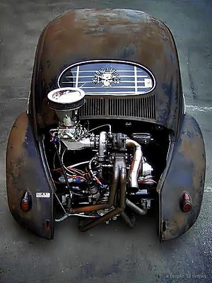
Up until about 2010 I was more into VW Beetles. In the early 2000s the RatRod (or Rat Look, as previous trends were called "Cal(ifornia) look" and German looker") trend hit the VW sceene, and it went in several directions. One of those was the beetles with rusted out/patina paint bodies, but perfectly restored floorpans, upgraded and/or restored brakes and suspension. Under a rusted out engine lid there was most likely a perfectly restored (often tuned) engine with chrome and fresh paint. These beetles often had very expensive parts, including rims and tires worth twice the cost of the car. The following picture is an example of such a car (not mine):


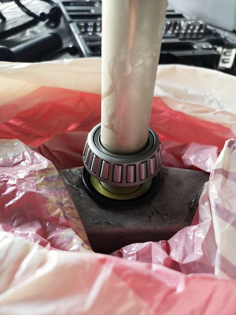
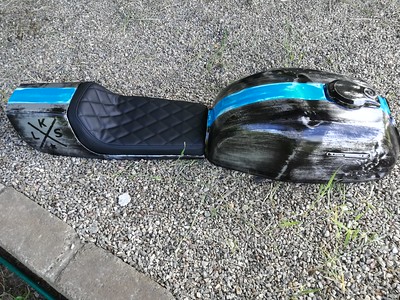
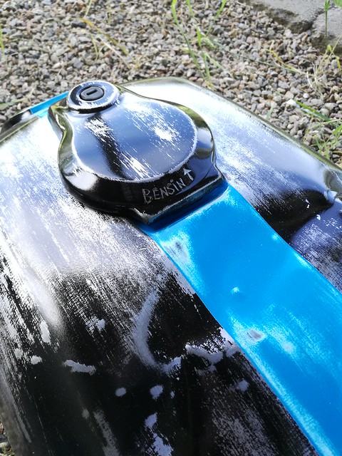
The "rat" came from my decision to give the bike a "patina"-look, with banged up gas tank, dented exhaust, worn sidecovers, "patina"-paint and so on. I wanted the brakes, wheels, electronics and to some degree; the engine, to look good. Here's some "Patina":


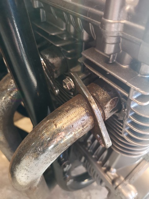
Before the fork conversion there was very few expensive parts, but I agree that the bike is more "fake patina" than "rat" at this stage.

I don't know what you guys think.. The beetle below counts as a "rat look beetle", with new chrome and nice wheels. The patina seems fake, and it's probably just a paint-job and new upholstery away from show quality.
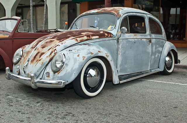
Bug by Erik Jordan, on Flickr

I think that, to me, my bike will always be the "rat cafe racer". But I'm not too concerned with what the term actually means.
 
I designed and rendered Version 1 of the switch housing. I'll 3D print one tomorrow to see if it seems OK.


51083397658_2a82d53179_z.jpg

51086851861_a633381328_z.jpg

51001927104_c57ee3a9e4_z.jpg
 
Modelled the bakside and printed both parts:


Printing the clamp lying down wasn't a good idea..

Both because of finish and strength:


The housing turned out ok, one of the threaded holes was a bit off. I'll correct it and print new ones. The clamp I'll print lying on its side.
 
I'd also print that as a solid piece. It takes longer but will be a lot stronger. Nice design though.
 
I'd also print that as a solid piece. It takes longer but will be a lot stronger. Nice design though.
Thanks! I adjusted wall thickness to 2mm, so the part is now solid in all the places that matter :) When my cnc-router is finished I light mill New ones in aluminium
 
I removed the old bearings from the stem, and was about to press the new lower bearing on. The bearings are conversion bearings from All Balls. In the package was these two spacers. They are about the same with as the stem, and I'm not sure where they go.. Anyone who knows? There a two spacers in the pack with the lower bearing (tapered bearing) and two in the pack with the upper bearing.

The spacers look like this:


Well, I'replying to my own post ;) I found this in an old post from 2006, so it's strange that my kit didn't include instructions. Maybe they're online somewhere.

"This kit is supplied with (2) spacers that are used by various applications
to make up for thickness differences between the taper bearings and the ball
stacks.

We have put instructions for the use of these spacers in kits since last
year, but if you have an earlier kit there may not be any instructions.

To determine which, if any washer is required measure the stack height of
the ball bearing assemblies (place a few ball between the races of both the
top and bottom bearing sets) and compare this measurement to the stack
height of both taper bearings. Select a washer to put the difference in
stack height to 1 mm. If the stack height is already within 1 mm then do
not use any washer.

The washer will be placed onto the stem first (before the seal and taper
bearing)

We do have some swing arm kits for street applications, but not a complete
line. If you can supply us with the dimension of the components we can
typically supply all or some of the parts.

Regards
Kevin"

I'll put the stem in the freezer until I get to measure the old bearings :)
 
Right side controls finished, I think it works well together with the throttle assembly;

 
Thought about the "Rat"-thing and noticed that I've already changed it over at thegsresources.com. But it's still "Dented" ;)
 
Went on to remove the old fork and bearings today. PO had replaced the old bearings with tapered bearings and the lower bearing (the part that sits in the frame) was a real headscratcher.. the angle is such that a screwdriver will not catch the edge. I tried to make an ad-hoc tool:


Didn't work so well..:


Then I tried this:


Small cuts with a hacksaw.


Pushed the tube up through the frame, took a punch and hammer, and bent all the tabs outwards. Went full sircle two/three times with light force. Gave the tube a few blows with a hammer and the bearing dropped to the floor. No scratches in the frame. Much easier I think than heating the frame with a torch (and burning the paint), welding the bearing (shrinking by heat), grinding it with a Dremel or other tips I found on the web.
 
The instructions for the All Balls conversion say to measure the old and the new lower bearing, and shim the difference if they are more than one mm apart.
Here's the old one:


And here's the new. No need for spacers:
 
I think those of you that have followed my build noticed early on that I didn't have much mechanical experience. It's mostly trial and error, and lots of research in advance. I keep at it because I really enjoy the process. I think I'm getting better at it and when enough time and effort is applied, nice things appear :)

Today I got a reminder that I'm still a newbie at many things. I read online that if you put the stem in the freezer, the bearing should "slide on without much effort". Can't say it did. I couldn't press it on by hand anyway. Adding to that, after a couple of minutes in room temperature frost appeared on the stem because of humid air. I don't want to trap all that moisture behind the bearing, so I'll wait for it to dry. Lesson learned.. Maybe this works for stem/bearing combos with less size difference. I have access to a press at my dads house, but it's an hour away. I want to see the fork on today, so I think I'll just use the old bearing and a tube and hammer it down. Here's picture of the frosted stem, straight from 20 celcius below zero (-4F);)

 
The frost won't hurt, and the term slide on easy is relevant, It means you can tap it on with a tube and mallet with less effort. In won't just slide down. Using the old bearing and a tube is a good way to do it.
 
The frost won't hurt, and the term slide on easy is relevant, It means you can tap it on with a tube and mallet with less effort. In won't just slide down. Using the old bearing and a tube is a good way to do it.
Thanks :)
 
Back
Top Bottom