We noticed you are blocking ads. DO THE TON only works with community supporters. Most are active members of the site with small businesses. Please consider disabling your ad blocking tool and checking out the businesses that help keep our site up and free.
You are using an out of date browser. It may not display this or other websites correctly.
You should upgrade or use an alternative browser.
You should upgrade or use an alternative browser.
1981 GS750E (GSX750E) Dented Cafe Racer ( Currently doing GSX-R USD conversion)
- Thread starter LKS
- Start date
Great! When I planned the fork-swap, I was afraid of getting too much trail and a slow turning bike. But this might ok then?With more than 4 inches of trail, you should be stable, even when the front dives and back lifts under hard braking. Won't need a stabilizer.
Last edited:
pidjones
Over 1,000 Posts
Well, it won't turn like a sport bike, but it should be Ok. That is in the ballpark of many standards.Great! When I planned the fork-swap, I was afraid of getting too much trail and a slow turning bike. But this might ok then?
Well, it won't turn like a sport bike, but it should be Ok. That is in the ballpark of many standards.
That's what I hoped for
") I'm not sure how well the Koni shocks perform. They're Koni 7610 with five way rebound adjustments (now sold as Ikon 7610) that I god for free because they needed a rebuild. If they're too bad, I'll rather buy some longer shocks and shave a little off on rake and trail that way.
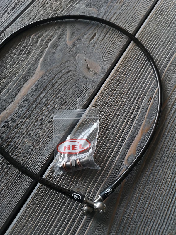
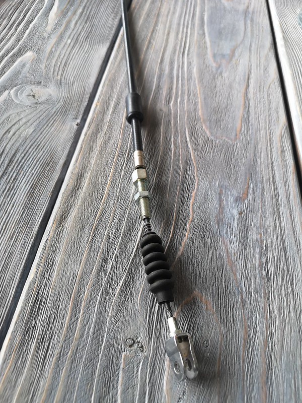
I'm not sure how well the Koni shocks perform. They're Koni 7610 with five way rebound adjustments (now sold as Ikon 7610) that I god for free because they needed a rebuild. If they're too bad, I'll rather buy some longer shocks and shave a little off on rake and trail that way.Not much happening.. but I got some stuff in the mail; A HEL brake line for the rear (they were on sale for some models) and an original (I hope, it says "made in Japan" on the sleeve) clutch cable. The clutch is extremely hard to pull, and I don't want to search for other faults before I've eliminated the cable as the source.
The clutch on my KLR was so stiff it gave me an rsi in my left elbow. Since then I've replaced the lever and the cable and it made a huge difference, especially the cable.
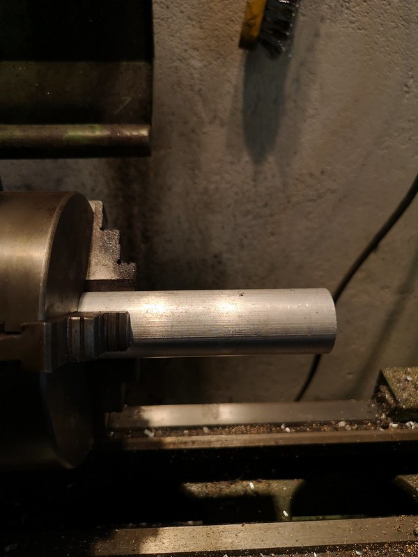
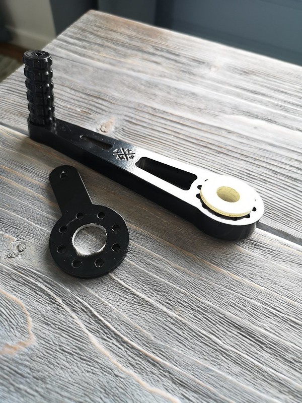
One other thing I did was to lengthen the clutch actuator arm on the clutch assembly itself. This gives move pull on the clutch itself but requires less effort to do so (something to do with physics!) and it really helped. I wonder if you could do something similar? Here's the before -

and the (pre-grinder and paint) after - with a ¼" piece of steel added in to add length -

One other thing I did was to lengthen the clutch actuator arm on the clutch assembly itself. This gives move pull on the clutch itself but requires less effort to do so (something to do with physics!) and it really helped. I wonder if you could do something similar? Here's the before -
and the (pre-grinder and paint) after - with a ¼" piece of steel added in to add length -
The clutch on my KLR was so stiff it gave me an rsi in my left elbow. Since then I've replaced the lever and the cable and it made a huge difference, especially the cable.
One other thing I did was to lengthen the clutch actuator arm on the clutch assembly itself. This gives move pull on the clutch itself but requires less effort to do so (something to do with physics!) and it really helped. I wonder if you could do something similar?
That's smart
The arm on the GS is already pretty long and I have a new lever.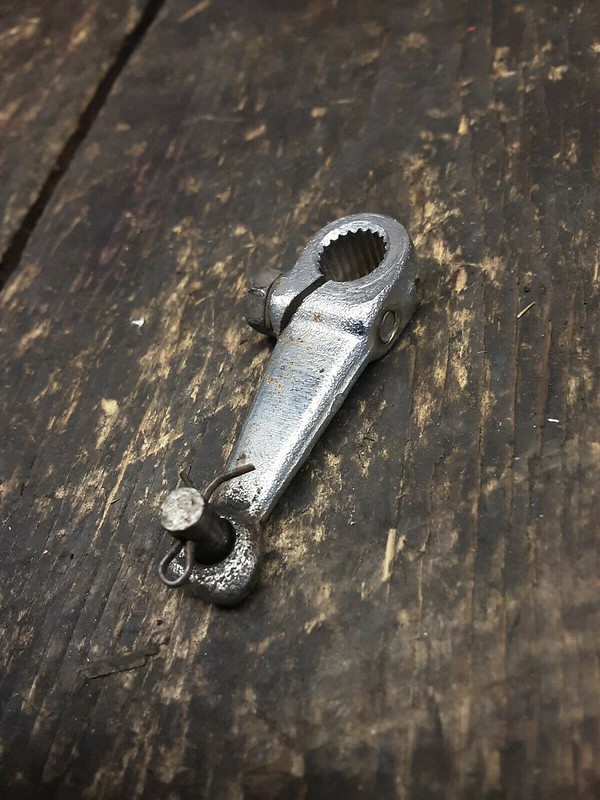
I don't know how hard the clutch should be to pull, but it's so hard that i have problems twisting the actuator arm by hand, and I'm average strength (I guess). I've heard the clutch basket can get grooves that make the clutch stick, so if the new lever and cable don't work I'll open the clutch and check that next
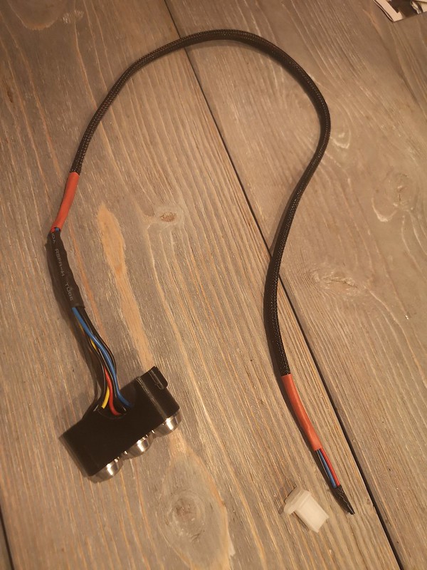
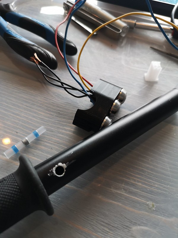
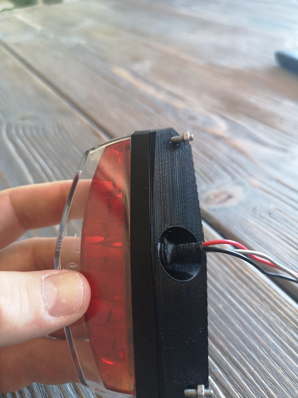
Started to do the wiring for the controls. I'm drilling a hole in the clip-on tubes for the wires (from inside the controls) and I'm running the wires inside nylon sleeves for protection and looks. I wont bother with Weather Pack connections as the connections will be inside the headlight.
I've removed the screws from the switch-terminals and soldered on wires to make sure they don't vibrate loose. I'm aware of the opinions on soldering from earlier discussions, but my opinion is that a few soldered points aren't any problems.
I've removed the screws from the switch-terminals and soldered on wires to make sure they don't vibrate loose. I'm aware of the opinions on soldering from earlier discussions, but my opinion is that a few soldered points aren't any problems.
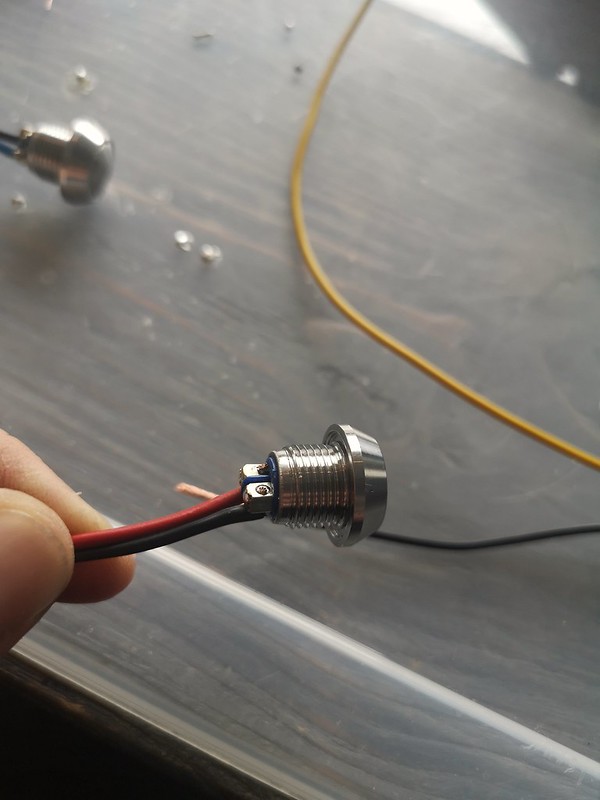
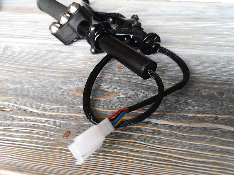
The front is slowly coming together again. I'm not using Weather Pack connectors here as it's much easier to put the clip-ons together if the connectors fit through the clamps and the connectors will be located up under the tank so waterproofing isn't as important. I think the result looks pretty clean

This is a 6mm hole. I bored it up to 8mm after i took the photo so I could extend the nylon sleeve inside the housing. That makes for two extra layers of abrasion-protection; the nylon woven sleeve and the heat shrink sleeve
The tool is the same one i use for the Wather Packs. People who use a lot of WP connectors will most likely have a more expensive tool that doesn't require one step pr crimp. I have the less expensive one. It takes longer to use, but is more versatile i guess.
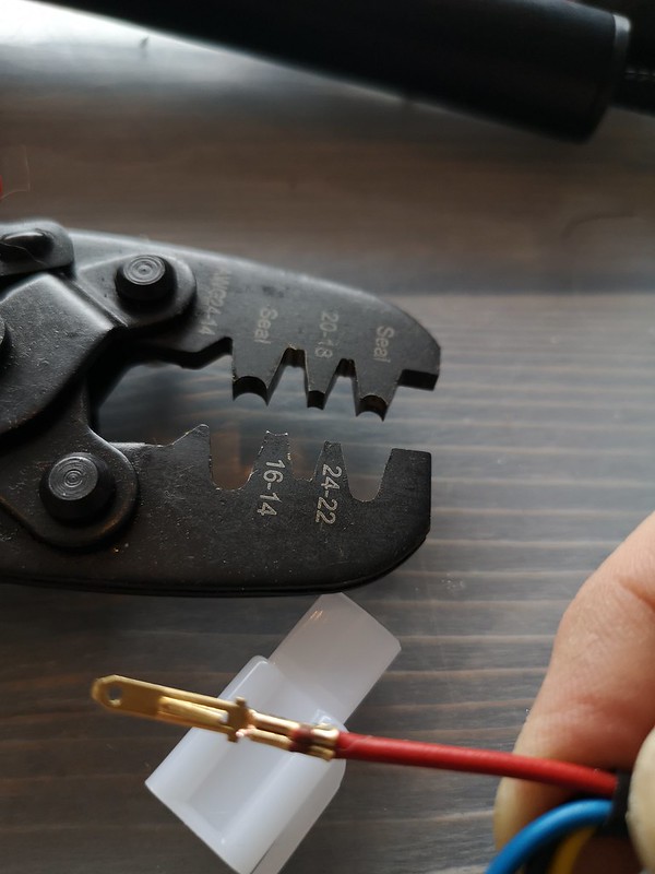
And here's the result:
This is a 6mm hole. I bored it up to 8mm after i took the photo so I could extend the nylon sleeve inside the housing. That makes for two extra layers of abrasion-protection; the nylon woven sleeve and the heat shrink sleeve
The tool is the same one i use for the Wather Packs. People who use a lot of WP connectors will most likely have a more expensive tool that doesn't require one step pr crimp. I have the less expensive one. It takes longer to use, but is more versatile i guess.
And here's the result:
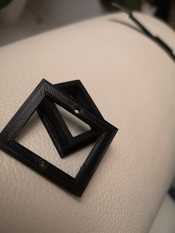
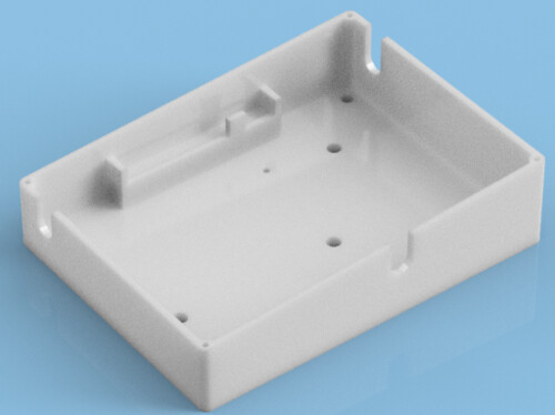
I made a housing for the Motogadget Mini. I'll glue this into the triple so I won't have to glue the Mini directly.

3D printing doesn't give a perfect surface. When the CNC-router is finished, I'll probably go back and recreate these parts in aluminum. Meanwhile it's a cheap and easy way to prototype and test parts
3D printing doesn't give a perfect surface. When the CNC-router is finished, I'll probably go back and recreate these parts in aluminum. Meanwhile it's a cheap and easy way to prototype and test parts
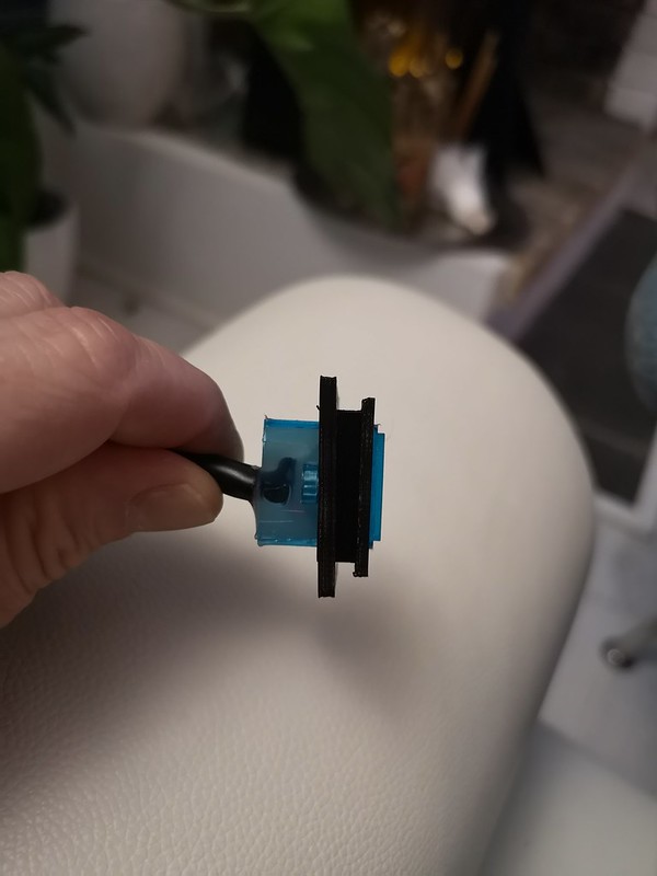
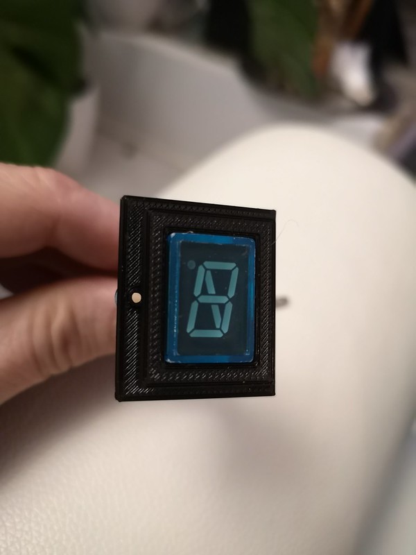
And I made one for the gear-indicator:
I think that's the last part I need to print for a while. There's some wiring left and connecting the front brakes, and then the front conversion is done. Then the bike will be rideable again
Still need to make a proper mount for the registration plate, finish the rear brake and left side rear set before I can take it for a longer spin. Then, there's the right hand side cover and proper mounts for the rear sets. I should stop reminding myself of how much work I'm putting into this.. but it's a great hobby
I think that's the last part I need to print for a while. There's some wiring left and connecting the front brakes, and then the front conversion is done. Then the bike will be rideable again
And for those of you that thinks this has become a 3D-printing thread, I'll soon be doing the linkage for the gearshifter and the front brakes.
In that regard, I have a question about steel reinforced braided hoses. The set I ordered earlier are for the original fork. Those are too long for the GSX-R fork with clip-ons. They are long enough that I can run one of them from the master down to the right caliper and the other one from the right caliper, over the fender and down to the left caliper. They're not long enough to ron two separate lines from the master.
The problem is that the banjos aren't properly lined up for this. Is it possible to rotate the banjos without ruining the brake lines?
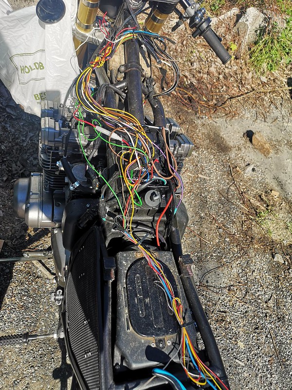
This is the mess I stitched together last summer to get the bike rideable.. Hurts my eyes to look at it

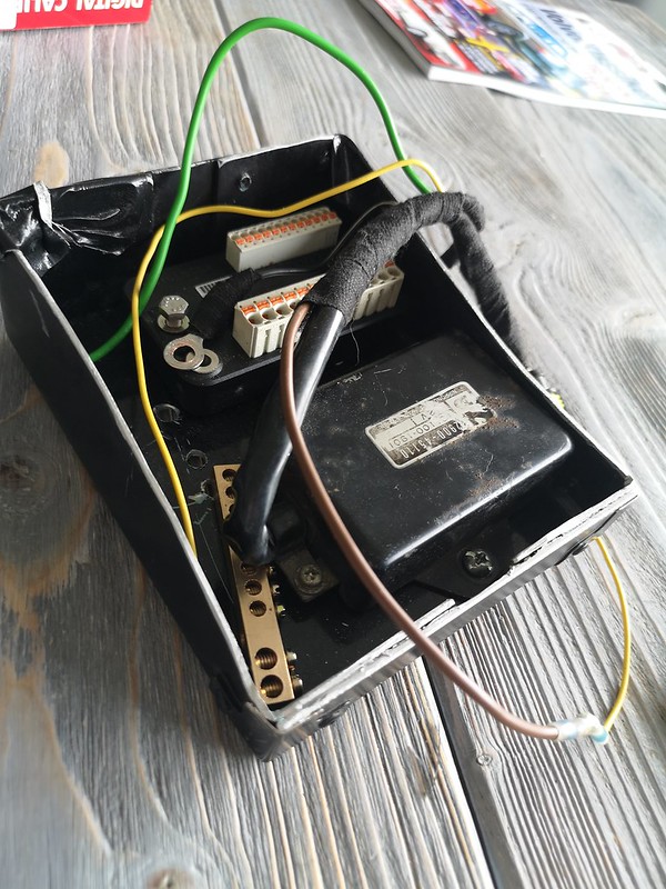
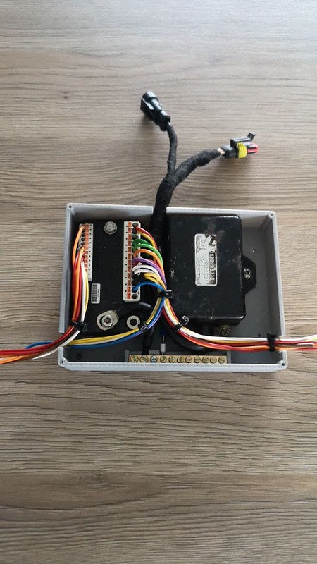
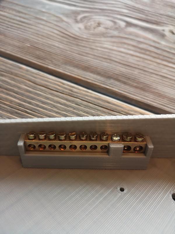
This is the new electronics box with the M-unit Blue and ignition module. I also integrated a copper ground terminal.
I'l draw some sketches to see how to best route the rest of the cables and make Weather Pack connectors for the different cable clusters.
This is the new electronics box with the M-unit Blue and ignition module. I also integrated a copper ground terminal.
I'l draw some sketches to see how to best route the rest of the cables and make Weather Pack connectors for the different cable clusters.
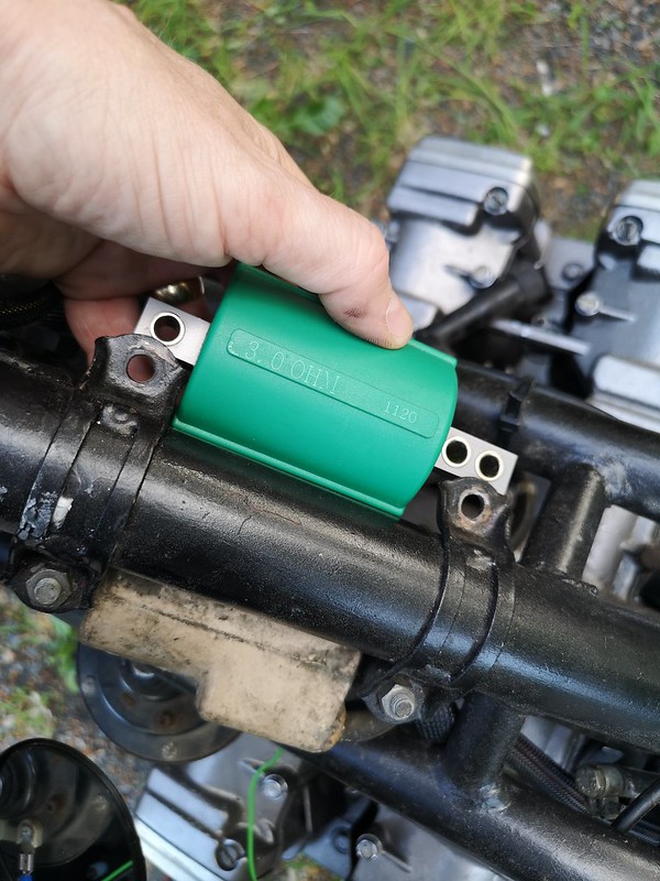
Well.. Today I'm both happy and annoyed with my self. Last summer I spent hour after hour trying to get the petcock to flow enough gas to make the bike pull at higher RPMs. I overhauled the carbs, changed fuel-filter and more. I was convinced that the only thing I had changed from when the bike ran well was the little pocket-bike fuel-tank. I heard of someone that had the same problems and found out that it was a faulty coil. These bikes seem to run quite smooth on low RPMs, even when firing on only two of the cylinders. As the spark wires are in bad condition and one of the coils seemed to have leaked, I ordered a set of green Dynas with wires.
While I waited for the Dynas I found an old clip from when I did the first test run. And what do you know.. The bike was wired up with only the bare essentials, and with spring loaded connectors. Seems like I was wrong about the fuel tank, and I decided to check the wiring. There was all sorts of tings wrong with the weather pack connector for the coils:
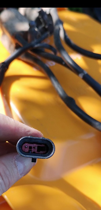
It's a bit hard to see, but it's supposed to be three pins in this connectors in this plug. The middle one is 12V, the two outer pins are for each coil. One of them is pushed back by the bent plastic guide-pin. This was one of the first connectors I made, and I didn't have any previous experience. I managed to get two different pins mixed up. They are almost identical, but when you use the wrong one the won't lock in place. This error made one of the coils go dead of course, and I'm pretty sure the bike will run as it should after fixing this
Pretty annoyed that I wasted countless hours, and only got one trip on the bike last summer :/ But pretty happy that I found the error. I was going install the Dyna coils, but it seemed like they needed some adapters:
I decided to just fix the connector in stead. After I put everything together, I noticed it's possible to remove the adapters from the old ones. Doesn't matter.. I wanted to test the old ones anyway. I'll change coils later
I have a lot more wires to sort out, but I'm getting the hang of it and taking the time it needs to be done correctly.
While I waited for the Dynas I found an old clip from when I did the first test run. And what do you know.. The bike was wired up with only the bare essentials, and with spring loaded connectors. Seems like I was wrong about the fuel tank, and I decided to check the wiring. There was all sorts of tings wrong with the weather pack connector for the coils:
It's a bit hard to see, but it's supposed to be three pins in this connectors in this plug. The middle one is 12V, the two outer pins are for each coil. One of them is pushed back by the bent plastic guide-pin. This was one of the first connectors I made, and I didn't have any previous experience. I managed to get two different pins mixed up. They are almost identical, but when you use the wrong one the won't lock in place. This error made one of the coils go dead of course, and I'm pretty sure the bike will run as it should after fixing this
Pretty annoyed that I wasted countless hours, and only got one trip on the bike last summer :/ But pretty happy that I found the error. I was going install the Dyna coils, but it seemed like they needed some adapters:
I decided to just fix the connector in stead. After I put everything together, I noticed it's possible to remove the adapters from the old ones. Doesn't matter.. I wanted to test the old ones anyway. I'll change coils later
I have a lot more wires to sort out, but I'm getting the hang of it and taking the time it needs to be done correctly.